EP1941882A2 - Briquet repliable - Google Patents
Briquet repliable Download PDFInfo
- Publication number
- EP1941882A2 EP1941882A2 EP06850454A EP06850454A EP1941882A2 EP 1941882 A2 EP1941882 A2 EP 1941882A2 EP 06850454 A EP06850454 A EP 06850454A EP 06850454 A EP06850454 A EP 06850454A EP 1941882 A2 EP1941882 A2 EP 1941882A2
- Authority
- EP
- European Patent Office
- Prior art keywords
- swing
- arm
- lighter
- pipe assembly
- aforementioned
- Prior art date
- Legal status (The legal status is an assumption and is not a legal conclusion. Google has not performed a legal analysis and makes no representation as to the accuracy of the status listed.)
- Withdrawn
Links
- 239000002828 fuel tank Substances 0.000 claims abstract description 13
- 239000000446 fuel Substances 0.000 claims description 21
- 230000000694 effects Effects 0.000 claims description 6
- 230000000994 depressogenic effect Effects 0.000 abstract 1
- 230000001681 protective effect Effects 0.000 description 16
- 230000002093 peripheral effect Effects 0.000 description 7
- 239000011324 bead Substances 0.000 description 3
- 229920003002 synthetic resin Polymers 0.000 description 3
- 239000000057 synthetic resin Substances 0.000 description 3
- 230000005611 electricity Effects 0.000 description 2
- 239000000463 material Substances 0.000 description 2
- 239000002184 metal Substances 0.000 description 2
- 239000004677 Nylon Substances 0.000 description 1
- 230000003213 activating effect Effects 0.000 description 1
- 238000007664 blowing Methods 0.000 description 1
- 230000006835 compression Effects 0.000 description 1
- 238000007906 compression Methods 0.000 description 1
- 238000001816 cooling Methods 0.000 description 1
- 238000007689 inspection Methods 0.000 description 1
- 229920001778 nylon Polymers 0.000 description 1
- 230000010355 oscillation Effects 0.000 description 1
- 230000037361 pathway Effects 0.000 description 1
- 230000000717 retained effect Effects 0.000 description 1
- 238000000926 separation method Methods 0.000 description 1
- 239000004449 solid propellant Substances 0.000 description 1
- 230000001131 transforming effect Effects 0.000 description 1
Images


Classifications
-
- F—MECHANICAL ENGINEERING; LIGHTING; HEATING; WEAPONS; BLASTING
- F23—COMBUSTION APPARATUS; COMBUSTION PROCESSES
- F23Q—IGNITION; EXTINGUISHING-DEVICES
- F23Q2/00—Lighters containing fuel, e.g. for cigarettes
- F23Q2/16—Lighters with gaseous fuel, e.g. the gas being stored in liquid phase
-
- F—MECHANICAL ENGINEERING; LIGHTING; HEATING; WEAPONS; BLASTING
- F23—COMBUSTION APPARATUS; COMBUSTION PROCESSES
- F23Q—IGNITION; EXTINGUISHING-DEVICES
- F23Q2/00—Lighters containing fuel, e.g. for cigarettes
- F23Q2/16—Lighters with gaseous fuel, e.g. the gas being stored in liquid phase
- F23Q2/164—Arrangements for preventing undesired ignition
Definitions
- This invention relates to a lighter (igniter) that drives a piezoelectric unit by activating an operating component and that emits a flame from the tip of a swing-arm that extends from the lighter body.
- the invention relates to a foldable lighter which is provided with a swing-arm pivotally attached to the lighter body.
- lighters have been used for such devices as lighting gas burners and igniters for solid fuels and fireworks.
- a lighter is a well known lighter (Japanese Unexamined Patent Application Publication H9-133359 ( Fig. 1 )) that has a tip pipe (extension) extended in a rod-shape from the body for emitting a flame.
- the lighter has a gas tank and a piezoelectric unit operated by an operating component, and by operating the operating component a flame is emitted from the tip of the tip pipe.
- a lighter of this type can safely and easily ignite objects without burning the user, but there is a problem in that comparatively more space is required to store the lighter due to lengthening of the lighter overall dimensions.
- lighters that can be made compact by extending and collapsing from the lighter body a rod-shaped extension for emitting a flame or can be folded when not in use.
- a pistol-shaped lighter Japanese Examined Patent Application Publication S47-7511 ( Fig. 2 )
- a flame-blowing tube is located in the tip of the telescopic barrel.
- a foldable lighter that has a rod-like tip pivotally attached to one side of the lighter body.
- a tip portion an elongated tube
- the space that accommodates the lighter may be relatively small. After use of the lighter, the burner pipe is in a hot state, and there is a risk of burning when the exposed burner pipe is inserted into the barrel prior to cooling. Also, there is a danger of scorching clothing that contacts the hot burner pipe.
- a foldable lighter comprising:
- the lighter housing contains an axle portion, and the swing-arm has an outer cylindrical sleeve that is slidingly fitted onto the axle portion with the possibility of free rotation.
- the swing-arm also contains a cylindrical wall that is made integrally with the cylindrical sleeve and forms an annular space.
- the end of the pipe assembly on the lighter-body side has a T-shaped configuration, and a transversely arranged portion of the T-shaped end may interact with an engagement member.
- the foldable lighter of the invention Located in the lighter body or in the swing-arm that is pivotally connected to the end of the lighter body is the foldable lighter of the invention, which has a cylindrical wall that forms an annular space coaxial with the axis of rotation of the swing-arm.
- the swing-arm slidingly holds a pipe assembly that retains a portion of a guide tube so that in the folded position of the swing-arm, the end of the pipe assembly on the side of the lighter body extends to the aforementioned annular space, and the annular space of the lighter body has a stopper acting so that during rotation of the swing-arm the fuel-nozzle end of the pipe assembly may protrude from the opening of the swing-arm under the effect of the aforementioned rotation and additionally has an engagement member acting so that the aforementioned nozzle-side end of the pipe assembly can be withdrawn into the swing-arm. Therefore, because of these conditions, the following effects are possible.
- the pipe assembly protrudes from the swing-arm into a position that allows ignition by merely turning the swing-arm into the open position, and even if the pipe assembly is in a hot state after use, the swing-arm can be turned into the folded position without any contact of the user with the hot pipe assembly.
- the lighter is in the folded condition, the user is protected from burns and clothing is protected from scorching. Since the lighter is folded, it needs a small space for storage.
- the swing-arm contains an axle portion, a cylindrical sleeve, which is slidingly fitted onto the outer periphery of the axle portion, and a cylindrical wall, which forms an annular space ands is made integrally with the aforementioned cylindrical sleeve, it becomes possible to provide smooth rotation of the swing-arm.
- the T-shaped end of the pipe assembly on the lighter-body side and the transverse element on the T-shaped end that interacts with the engagement member make it possible to extend the pipe assembly from the swing-arm or withdraw the pipe assembly into the swing-arm in response to turning the swing-arm from one position to the other.
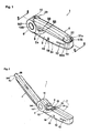
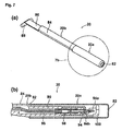
- FIG 1 is a perspective view showing a lighter 1 in the folded form.
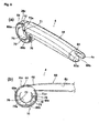
- Figure 2 is a perspective view showing lighter 1 in the open state ready for use.
- lighter 1 has a lighter body 2 for grasping by a user's hand and a swing-arm 4 axially supported to swing freely at one end of the lighter body 2.
- a later-described piezoelectric unit 102 ( Figure 8 ) and a fuel tank 106 ( Figure 8 ).
- a swing-mount 6 is formed at one end of lighter body 2, and a swing-mount unit 10 is formed on one end of swing-arm 4 and is mounted to swing-mount 6 for support by swing-mount 6.
- An operating button 8 (operating component) is installed in lighter body 2 to be exposed from an opening 32 in the vicinity of swing-mount 6. Pressing this operating button 8 with a finger causes ignition.
- an inspection window 12 is formed to enable checking of the remaining quantity of fuel such as liquefied gas.
- an opening 18 is formed in lighter body 2, from which protrudes an adjustor protrusion 16 for adjusting the length of the flame to be emitted.
- a pipe assembly 20 is housed in swing-arm 4 with the ability to slide in the lengthwise direction of swing-arm 4. When swing-arm 4 is in the closed position (housing position), specifically when it is folded for overlapping by lighter body 2, as shown in Figure 1 , pipe assembly 20 is pulled within swing-arm 4.
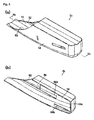
- swing-arm 4 when swing-arm 4 is in the open position (position for use), specifically when swing-arm 4 is opened to an angle of 90 degrees or more in relation to lighter body 2, as shown in Figure 2 , a tip tube 20a of a pipe assembly 20 is projected from an exposure port 60b of a leading edge 4a of swing-arm 4.
- Lighter body 2 has two reciprocally engaging components, specifically a half-lighter body 2a and a half-lighter body 2b, and a full-body cover 2c that maintains the reciprocally combined condition of half-bodies 2a and 2b.
- Figures 3 to 5 the following section describes half-bodies 2a and 2b and a full-body cover 2c.
- Figure 3 is a perspective view showing half-lighter body 2a, which is the forward-facing half-body in Figures 1 and 2 , with Figure 3(a) displaying the half-lighter body 2a as seen from the outside and Figure 3(b) displaying the half-lighter body 2b as seen from the inside.
- Figure 4 shows half-lighter body 2b, which is the half-body opposite half-lighter body 2a of Figure 3 ;
- Figure 4(a) is a front view as seen from the inside, and
- Figure 4(b) is a perspective view also as seen from the inside.
- Figure 5 shows full-body cover 2c,
- Figure 5(a) is a perspective view,
- Figure 5(b) is a perspective view displaying the cross-section along line 5b-5b of Figure 5(a) .
- half-lighter body 2a is integrally formed from a synthetic resin, for example, and consists of a cylindrically shaped axle portion 6a (pivot axle) structured as part of swing-mount 6 and a main portion 22a.
- the half-body has a circular opening 24a, a cylindrically shaped axle socket 30a formed in succession with an opening 24a, and an annular wall (cylindrical wall) 26a formed at the outer side of an axle socket 30a and along the same axis as axle socket 30a.
- a cutout 32a is formed to house the upper portion of an operating button 8.
- Main portion 22a has an upper wall 34a and a lower wall 36a extending approximately in parallel. At upper wall 34a and lower wall 36a, flange sections 38a and 39a are integrally formed to extend on opposite sides of axle portion 6a.
- the outer surface of main portion 22a is formed with channel 37a in the vertical direction for use in positioning full-body cover 2c. Furthermore, the vertical orientation shown here applies to the drawings referred to in the description.
- axle portion 6a This section describes in further detail axle portion 6a with reference to Figure 3(b) .
- Two ribs are formed at an outer surface 31a of axle socket 30a, specifically stoppers 40a and 41 a at a prescribed interval.
- the stoppers 40a and 41a have respective notches 42a and 43a formed between each notch and the outer periphery 31a of the axle socket 30a.
- a cutout 44a is formed axially inward.
- a protrusion 46a is formed to protrude inward in the vicinity of a cutout 44a, and in a separated position at the opposite end of main portion 22a from protrusion 46a is a socket seat 50a having an inward-facing elliptical recess 48a.
- a socket seat 50a is the shaft receptacle for operating button 8.
- Half-lighter body 2b is a shape approximately reflective of half-lighter body 2a, and is provided with an axle 6b and a lighter body 22b.
- Axle 6b has an annular wall (cylindrical wall) 26b of the same outer diameter as axle portion 6a.
- Stoppers 40b and 41b are on an outer peripheral surface 31b of an axle socket 30b and correspond to stoppers 40a and 41 a. Stoppers 40a and 40b together are referred to as engagement member 40, and stoppers 41 and 41 b together are referred to as stopper 41.
- Main lighter body 22b is provided with cutout 32b, which corresponds to cutout 32a. Moreover, cutouts 32a and 32b enable structuring of a single opening 32 for receiving operating button 8 when half-bodies 2a and 2b are assembled ( Figures 1 and 2 ).
- protrusion 46b and socket seat 50b are respectively identical to and correspond with previously described protrusion 46a and socket seat 50a.
- flange sections 38b and 39b are in positions corresponding to previously described flange sections 38a and 39a. Socket seat 50a and socket seat 50b together form axle socket 50.
- flange sections 38a and 38b together form support section 38, and 39a and 39b together form support section 39.
- channel 37b is formed in main portion 22b of half-lighter body 2b and corresponds to channel 37a.
- Full-body cover 2c is used by first engaging the inner surfaces of previously described half-bodies 2a and 2b and then fitting full-body cover 2c over half-bodies 2a and 2b from the opposite end of the combined half-bodies 2a and 2b.
- Full-body cover 2c has an opening 54 formed by the pair of edges 52 and 52, which are curved upward at one end.
- ribs 56a, 56b, and 56c that protrude into the interior of the full-body cover 2c for positioning previously described piezoelectric unit 102 and fuel tank 106 at the time of housing ( Figure 8 ).
- Rib 56a is formed as a pair of ribs at left and right in the lengthwise direction of full-body cover 2c; similarly, rib 56b is formed as a pair of ribs at top and bottom in the lengthwise direction ( Figure 8 ). Respective opposite side ribs 56a, 56b, and 56c are not shown in Figure 5(b) . Rib 56c is formed vertically at the farthest inner section. In addition, at each inner surface of sidewalls 14, a bead 58 is formed for engaging respectively to channels 37a and 37b of half-bodies 2a and 2b at the time of receiving previously described half-bodies 2a and 2b. Only one side of bead 58 is shown in Figure 5 . By engaging bead 58 to channels 37a and 37b, full-body cover 2c is positioned and also fixed.
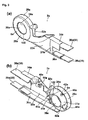
- Swing-arm 4 has a swing-mount unit 10 and a long protective cover 60 integrally formed to swing-mount unit 10.
- Protective cover 60 has a cavity 62 passing through the lengthwise direction within protective cover 60.
- Protective cover 60 which is made from a material with adiabatic properties such as a synthetic resin, is maintained to allow swinging of swing-arm 4 without touching tip tube 20a of pipe assembly 20.
- Swing-mount unit 10 is mounted for swinging by interposition support with free swinging between axles 6a and 6b of half-bodies 2a and 2b.
- Swing-mount unit 10 has an annular wall (cylindrical wall) 26c of approximately the same outer diameter as axles 6a and 6b.
- annular wall 26c At annular wall 26c, an annular step 64 is formed for crowning of annular walls 26a and 26b of lighter body 2.
- an opening 66 is formed for passage between the interior of annular wall 26c and cavity 62 of protective cover 60.
- an arching inner wall (outer cylinder) 70 is integrally supported on the same axis as annular wall 26c by three support walls 68a, 68b, and 68c mutually spaced in the circumferential direction.
- a cylindrical space is formed between arching inner wall 70 and annular wall 26c.
- Support walls 68a and 68c are positioned symmetrically to bind the center arching inner wall 70, and support wall 68b is positioned at the lower end of arching inner wall 70 between support walls 68a and 68b.
- axle sockets 30a and 30b are referred to as the inner cylinder in relation to the outer cylinder.
- the upper portion of arching inner wall 70 has a cutout that forms an opening 66.
- protrusion sections 72a and 72b are formed to protrude and to face half-lighter body 2b.
- Protrusion section 72a is formed in the lower section of support wall 68a
- protrusion section 72b is formed in a position approximately identical to that of support wall 68c.
- Bump-like protrusions 73 are formed on the leading edges of protrusion sections 72a and 72b facing inward. During assembly of swing-arm 4 and lighter body 2, these bump-like protrusions 73 of aforementioned protrusions sections 72a and 72b engage at three predetermined angles with notches 30c, 30d, and 30e of axle socket 30b of half-lighter body 2b.
- a protrusion (thick section) 74 is formed that extends in the circumferential direction.
- Protrusion 74 is formed along the edge at the lighter body 2b side of annular wall 26c and extends from the lower end of annular wall 26c in both directions toward support wall 68a and support wall 68c.
- Protrusion 74 extends slightly toward support wall 68a and extends more than half the distance along the circumference of support walls 68b and 68c.
- arching inner wall 70 is established with rib 76 protruding at a position approximately identical to that of support wall 68.
- arching inner wall 70 is formed with a slot 78 directly below rib 76.
- Protective cover 60 has a metal cap 60a with an exposure port 60b. By using latching hooks (not shown in the drawing), cap 60a engages a recess or opening (not shown in the drawing) formed in protective cover 60. Furthermore, it is acceptable to use a material with adiabatic properties, such as Nylon, for cap 60a.
- Pipe assembly 20 has a tip tube 20a made of metal and a tip pipe 20b on which tip tube 20a is installed.
- Tip tube 20a is of cylindrical shape and has a flame port 82 for emitting a flame from the tip.
- Tip pipe 20b is made from a synthetic resin, for example, and it has a plate-shaped extension 86 integrally formed with cylinder 84 onto which is installed leading-edge tube 20a.
- the tip of extension 8 specifically the end facing the body, is formed in a T-shape.
- a cylindrical protrusion 88 projects in opposing directions perpendicular to the lengthwise direction of pipe assembly 20 and to channels at both sides.
- a nozzle holder 90 is inserted into a cylindrical sleeve 84 in tip pipe 20b and is stored in tip tube 20a.
- a space 92 is formed in the lengthwise direction of tip tube 20a.
- a nozzle (flame-emitting nozzle) 94 and a gas pipe 96 linked to nozzle 94 is a nozzle (flame-emitting nozzle) 94 and a gas pipe 96 linked to nozzle 94.
- Nozzle 94 has a nozzle tip 94a and a nozzle body 94b into the tip of which is inserted nozzle tip 94a.
- Nozzle 94 is fixed to the leading edge of nozzle holder 90 so that nozzle tip 94a is at the outer side of nozzle holder 90.
- Gas pipe (flexible fuel conduit) 96 is linked by linking pipe 98 to nozzle body 94b of nozzle 94.
- Nozzle cover 100 is installed at the outer-side leading edge of nozzle holder 90 to protect nozzle tip 94a.
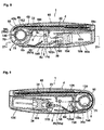
- FIG. 8 is a cross-sectional view along line 8-8 of lighter 1, as shown in Figure 1 .
- Figure 9 is a cross-sectional view along line 9-9 of lighter 1, as shown in Figure 1 .
- swing-arm 4 overlaps lighter body 2 in the closed condition, specifically, in the folded condition.
- Located within lighter body 2 is a piezoelectric unit 102, a housing 104 that holds the piezoelectric unit 102, and a fuel tank 106.
- Piezoelectric unit 102 has a sliding component 102a that is pressed so that the piezoelectric unit 102 generates electricity.
- Fuel tank 106 is a cylindrical body of a square cross-section that is installed and fixed in housing 104 on the opposite side of piezoelectric unit 102. Piezoelectric unit 102 and fuel tank 106 are positioned and retained by previously described ribs 56a, 56b, and 56c, as well as support sections 38 and 39. In addition, operating button 8 of lighter body 2 is axially supported for free swinging by axle socket 50 so as to face opening 32 of lighter body 2.
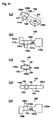
- FIG. 10 shows operating button 8
- Figure 10(a) is a perspective view
- Figure 10(b) is a top view
- Figure 10(c) is a side view
- Figure 10(d) is a front view.
- Operating button 8 has an upper wall 108 that in the top view is of a transforming shape from circular to elliptical by forming a large arching shape on one side and a small arching shape on the other side.
- a peripheral wall 110 encompasses the circumference of upper wall 108, and the inner side of peripheral wall 110 becomes a cavity.
- a plate 8a projects in the lateral direction, and one side of plate 8a, specifically toward the half-lighter body 2b side, an L-shaped engagement hook (hook component) 8b extends with upward inclination. At the leading edge of engagement hook 8b, a protrusion 112 is formed facing inward.
- Plate 8a contacts the lower edge of one side of opening 32 of lighter body 2, with operating button 8 located under the opening. In this way, operating button 8 does not project beyond opening 32.
- a pair of cylindrical shafts 8c used for axle support from axle socket 50 projects to a position corresponding to axle socket 50.
- the lower edge of peripheral wall 110 has a cutout 8d that faces downward.
- an arm 8e is integrally fixed downward from the other side of upper wall 108. At the lower side of this arm 8e, a curved protrusion 116 is formed to face sliding component 102a.
- axle socket 50 When operating button 8 is axially supported by axle socket 50, the previously described engagement hook 8b is positioned at swing-mount 6.
- curved protrusion 116 of arm 8e is positioned to contact sliding component 102a, or the vicinity thereof, with sliding component 102a in a condition being projected by outward biasing of a spring.
- shaft 8c is axially supported in elliptically shaped axle socket 50, and shaft 8c enables horizontal movement to the opposite side.
- circular axle sockets 30a and 30b of half-bodies 2a and 2b are inserted for free swinging within arching inner wall 70 of swing-arm 4.
- Figures 8 and 9 clearly show swing-arm 4 to be axially supported by lighter body 2.
- arching inner wall 70 of swing-arm 4 is axially supported for free swinging by axle sockets 30a and 30b of half-bodies 2a and 2b.
- Figure 8 shows axle socket 30b
- Figure 9 shows axle socket 30a.
- sleeve 146 is inserted and fixed at the inner side of unified axle sockets 30a and 30b.
- Sleeve 146 has a cylindrical shape and annular projections 147 at both sides ( Figures 1 and 2 ).
- an annular step 148 is formed at the outer peripheral edge of respective openings 24a and 24b of half-bodies 2a and 2b, as shown in Figure 3(a) and Figure 13 .
- annular projections 147 of sleeve 146 are engaged with annular step 148, and along with the fixing of sleeve 146 within axle sockets 30a and 30b, it supports half-bodies 2a and 2b in a manner that half-bodies 2a and 2b will not be separated.
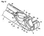
- FIG. 12 is a partial cross-sectional perspective showing swing-mount 6 and the related vicinity when swing-arm 4 is in the closed condition.
- Engagement hook 8b is positioned in the edge vicinity of annular wall 26c
- protrusion 112 of engagement hook 8b is positioned in the edge vicinity of the inner side of annular wall 26c of swing-arm 4. Therefore, protrusion 74 formed below the edge of annular wall 26c is spaced downward from engagement hook 8b.
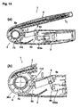
- FIG. 11(a) is a perspective view
- Figure 11(b) is a top view
- Figure 11(c) is a right-side view
- Figure 11(d) is a front view
- Figure 11(e) is a bottom view.
- Figure 13 is a partial cross-sectional perspective showing swing-mount 6 and the related vicinity.
- Lever 120 has a substantially flat and elongated shape, and a cylindrical spindle 120a projects in the sideways direction at a side edge 124a in the vicinity of one end.
- a first arm 121 the section extending toward the side of operating button 8 from spindle 120a
- a second arm 123 the section extending toward swing-mount 6
- a curved protrusion 120c is formed, having a position aligned with spindle 120a.
- a rectangular flange 120b projects toward the side opposite of spindle 120a and toward the lower surface 128 of side edge 124b.
- first arm 121 On first arm 121 is formed a rectangular plate 120d, which is larger than rectangular flange 120b.
- Lever 120 is axially supported by spindle 120a in an axle socket 122 ( Figure 3(b) ) having rectangular plate 120d at the side of operating button 8.
- Lever 120 is then supported by a compression coil spring (hereafter simply referred to as a spring) 130 located at the side of half-lighter body 2a.
- notch 8d of operating button 8 engages with rectangular plate 120d of first arm 121.
- Leading edge 120e of second arm 123 incorporating rectangular flange 120b is engaged with slot 78 of arching inner wall 70 of swing-arm 4.
- FIG. 14 is a vertical cross-section similar to Figure 6 and shows a partially open swing-arm 4 of lighter 1.
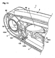
- Figure 15 is an enlarged cross section of primary components, specifically showing swing-mount 6, operating button 8, and the related vicinity.
- protrusion 88 of pipe assembly 20 separates from engagement member 40 and swings clockwise (in Figure 14 ). If a user places a finger or any other external object into the space between operating button 8 and swing-arm 4 and if the swing-arm 4 is inadvertently turned toward the closing direction, operating button 8 shifts downward in the direction shown by arrow 136.
- lever 120 engaged with operating button 8 swings counterclockwise per Figure 14 .
- leading edge 120e of lever 120 engages with slot 78 of arching inner wall 70 of swing-arm 4.
- operating button 8 presses further downward rectangular plate 120d of lever 120.
- leading edge 120e of lever 120 biases upward rib 76 formed with adjacent contact above slot 78.
- protective cover 60 of swing-arm 4 is prevented from shifting further downward.
- operating button 8 is difficult to press because of resistance on the side of lever 120.
- arm 8e of operating button 8 presses the sliding component 102a of piezoelectric unit 102 to some extent but does not reach the ignition point.
- Figure 16 is a cross-sectional view similar to Figure 14 but shows the parts of the lighter 1 in positions similar to Fig. 8 .
- Figure 16(a) is a cross-section of lighter 1 in the condition identical to that of Figure 14 .
- Figure 16(b) is a cross-sectional view that shows essential parts of the device when operating button 8 is further pressed.
- protrusion 74 is positioned in the vicinity of engagement hook 8b, but is not yet at the point of engagement.
- engagement hook 8b of operating button 8 engages with protrusion 74, as previously described. Specifically, protrusion 74 is inserted between protrusion 112 of engaging hook 8b and annular wall 26c. At this time, arm 8e of operating button 8 presses further on sliding component 102a, but not to the point of ignition. In order to ignite the lighter, shaft 8c of operating button 8 must shift to the right within axle socket 50 per Figure 16(c), and sliding component 102a must be further pressed by shifting operating button 8. However, protrusion 112 of engaging hook 8b does not allow shifting because it is engaged with protrusion 74.
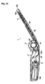
- FIG 17 is a partial cross-section showing swing-arm 4 in the open position at an approximate right angle.
- the previously described bump-like protrusions 73 of protrusion portions 72a and 72b are respectively engaged with notches 30d and 30e, the position of swing-arm 4 is maintained in this condition, and protrusion 74 is separated from engaging hook 8b. Accordingly, it is possible attmept ignition by pressing operating button 8, but ignition does not generally occur in this position. Even in the event of inadvertent ignition, the flame emitted from flame port 82 of swing-arm 4 will not blow near the hand that holds lighter body 2 and thus cannot cause a burn.
- Figure 18 is a vertical cross-section of lighter 1 that shows the condition in which swing-arm 4 has been opened approximately 150 degrees
- Figure 19 is a vertical cross-section of lighter 1 showing a position that differs from that in Figure 18 .
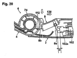
- FIG. 20 is an enlarged cross-sectional view showing the main components in the condition wherein operating button 8 has been caused to slide.
- arm 8e presses sliding component 102a of piezoelectric unit 102 for a prescribed distance, and piezoelectric unit 102 generates electricity. This causes an electric discharge in the vicinity of nozzle tip 94a.
- protrusion 74 of swing-arm 4 will engage with protrusion 112 of engaging hook 8b and will generate resistance, thus preventing closing to less than the prescribed angle. Accordingly, it is possible to prevent burns to the hand that holds lighter body 2 or scorching of clothing.
- FIG. 21 is a cross-sectional view along line 21-21 of Figure 8 and shows the operating condition of the fuel supply valve.
- Figure 21(a) shows the condition prior to ignition
- Figure 21(b) is a partial cross-sectional view that shows the condition after ignition.
- Sliding component 102a is positioned at the side of the fuel supply valve and has a lever depressor 102b integrally formed with sliding component 102a along the sliding direction of sliding component 102a. This lever depressor 102b shifts with the shifting of sliding component 102a.
- a fuel supply valve 142 is located in housing 104.
- Engaged with this fuel supply valve 142 is an L-shaped lever 144 axially supported for free oscillation to a shaft 145 within the plane of the drawing.
- Lever 144 has an engaging arm 144a engaged with fuel supply valve 142 and a drive arm 144b positioned in the vicinity of lever depressor 102b.
- a power line 140 ( Figure 8 ) is routed from piezoelectric unit 102 to nozzle 94 and the vicinity of nozzle tip 94a of tip tube 20a, and the power line 140 releases an electric discharge to ignite the gas emitted from nozzle tip 94a.
Landscapes
- Engineering & Computer Science (AREA)
- Chemical & Material Sciences (AREA)
- Combustion & Propulsion (AREA)
- Mechanical Engineering (AREA)
- General Engineering & Computer Science (AREA)
- Lighters Containing Fuel (AREA)
- Materials For Photolithography (AREA)
- Compositions Of Macromolecular Compounds (AREA)
Applications Claiming Priority (2)
| Application Number | Priority Date | Filing Date | Title |
|---|---|---|---|
| JP2005254866A JP4783093B2 (ja) | 2005-09-02 | 2005-09-02 | 折りたたみ式着火器 |
| PCT/IB2006/004151 WO2007110701A2 (fr) | 2005-09-02 | 2006-08-31 | Briquet repliable |
Publications (1)
| Publication Number | Publication Date |
|---|---|
| EP1941882A2 true EP1941882A2 (fr) | 2008-07-09 |
Family
ID=37926998
Family Applications (1)
| Application Number | Title | Priority Date | Filing Date |
|---|---|---|---|
| EP06850454A Withdrawn EP1941882A2 (fr) | 2005-09-02 | 2006-08-31 | Briquet repliable |
Country Status (5)
| Country | Link |
|---|---|
| US (1) | US7614874B2 (fr) |
| EP (1) | EP1941882A2 (fr) |
| JP (1) | JP4783093B2 (fr) |
| CN (1) | CN101984746B (fr) |
| WO (1) | WO2007110701A2 (fr) |
Families Citing this family (11)
| Publication number | Priority date | Publication date | Assignee | Title |
|---|---|---|---|---|
| US8653942B2 (en) | 2008-08-20 | 2014-02-18 | John Gibson Enterprises, Inc. | Portable biometric lighter |
| USD790527S1 (en) | 2016-05-17 | 2017-06-27 | Olloclip, Llc | Holder for a mobile device |
| USD820331S1 (en) | 2016-06-23 | 2018-06-12 | Worthington Torch, Llc | Air-assisted torch |
| CA3041031A1 (fr) | 2016-06-29 | 2018-01-04 | Worthington Industries, Inc. | Chalumeau comportant un capuchon de securite rotatif |
| USD845364S1 (en) | 2016-07-08 | 2019-04-09 | Worthington Torch, Llc | Torch having an extendable arm |
| WO2018208592A1 (fr) | 2017-05-08 | 2018-11-15 | Worthington Torch, Llc | Torche dotée d'un mécanisme de verrouillage |
| US10502419B2 (en) | 2017-09-12 | 2019-12-10 | John Gibson Enterprises, Inc. | Portable biometric lighter |
| CN110094754B (zh) * | 2019-05-05 | 2021-08-10 | 邵东弘邦电子有限公司 | 一种折叠式带保险装置点火枪 |
| US11933493B2 (en) * | 2021-01-22 | 2024-03-19 | Pro-Iroda Industries, Inc. | Tool with improved ignition efficiency |
| US11852342B2 (en) * | 2021-01-22 | 2023-12-26 | Pro-Iroda Industries, Inc. | Tool with improved ignition efficiency |
| US20250050525A1 (en) * | 2023-08-11 | 2025-02-13 | Jeovany Calero | Smart straight razor |
Family Cites Families (17)
| Publication number | Priority date | Publication date | Assignee | Title |
|---|---|---|---|---|
| JPS477511U (fr) * | 1971-02-24 | 1972-09-27 | ||
| US4538983A (en) | 1983-10-11 | 1985-09-03 | Noel E. Zeller | Foldable safety lighter |
| JPH0514172A (ja) * | 1991-06-28 | 1993-01-22 | Nec Corp | 入力回路 |
| US5597299A (en) * | 1993-05-24 | 1997-01-28 | Jon; Jong K. | Ignition safety device of gas lighter |
| US5697775A (en) * | 1994-08-18 | 1997-12-16 | Tokai Corporation | Safety device in lighting rods |
| JP3516153B2 (ja) | 1995-11-09 | 2004-04-05 | 株式会社東海 | ガス着火器 |
| US6726469B2 (en) * | 2000-11-03 | 2004-04-27 | Bic Corporation | Multi-mode lighter |
| US6908302B2 (en) * | 2000-11-03 | 2005-06-21 | Bic Corporation | Multi-mode lighter |
| US6916171B2 (en) * | 2000-11-03 | 2005-07-12 | Bic Corporation | Multi-mode lighter |
| US7311518B2 (en) * | 2000-11-03 | 2007-12-25 | Bic Corporation | Multi-mode lighter |
| US6488492B2 (en) * | 2000-11-03 | 2002-12-03 | Bic Corporation | Multi-mode lighter |
| JP3748066B2 (ja) * | 2001-02-19 | 2006-02-22 | 株式会社東海 | スライド式ライターの着火操作機構 |
| US6666679B1 (en) * | 2002-12-06 | 2003-12-23 | Easton Enterprises, Inc. | Utility lighter with an improved child safety device |
| JP2005061671A (ja) * | 2003-08-08 | 2005-03-10 | Nec Corp | ライター内蔵の携帯電子機器 |
| US7500850B1 (en) * | 2005-07-29 | 2009-03-10 | Colibri Corporation | Lighter with accessory |
| US20070160945A1 (en) * | 2006-01-09 | 2007-07-12 | Huang-Hsi Hsu | Foldable ignition gun |
| US20070160941A1 (en) * | 2006-01-09 | 2007-07-12 | Huang-Hsi Hsu | Lighter |
-
2005
- 2005-09-02 JP JP2005254866A patent/JP4783093B2/ja not_active Expired - Fee Related
-
2006
- 2006-08-31 US US12/065,128 patent/US7614874B2/en not_active Expired - Fee Related
- 2006-08-31 WO PCT/IB2006/004151 patent/WO2007110701A2/fr not_active Ceased
- 2006-08-31 CN CN2006800409445A patent/CN101984746B/zh not_active Expired - Fee Related
- 2006-08-31 EP EP06850454A patent/EP1941882A2/fr not_active Withdrawn
Non-Patent Citations (1)
| Title |
|---|
| See references of WO2007110701A2 * |
Also Published As
| Publication number | Publication date |
|---|---|
| US20080220386A1 (en) | 2008-09-11 |
| CN101984746A (zh) | 2011-03-09 |
| US7614874B2 (en) | 2009-11-10 |
| WO2007110701A3 (fr) | 2011-05-19 |
| JP4783093B2 (ja) | 2011-09-28 |
| CN101984746B (zh) | 2012-10-10 |
| WO2007110701A2 (fr) | 2007-10-04 |
| JP2007064603A (ja) | 2007-03-15 |
Similar Documents
| Publication | Publication Date | Title |
|---|---|---|
| US20100190121A1 (en) | Foldable igniter | |
| US6264463B1 (en) | Double-trigger child-resistant utility lighter | |
| EP1941882A2 (fr) | Briquet repliable | |
| US4538983A (en) | Foldable safety lighter | |
| US6682341B2 (en) | Child resistant actuator for piezoelectric lighter | |
| CN110603408A (zh) | 具有互锁机构的火炬 | |
| WO2001018450A1 (fr) | Briquet fonctionnel | |
| EP1956295A2 (fr) | Dispositif d'allumage pliable | |
| CA2329080C (fr) | Briquet polyvalent a mecanisme de verrouillage automatique a l'epreuve des enfants | |
| CA2413716C (fr) | Mecanisme d'allumage de briquets a systeme coulissant | |
| KR200474743Y1 (ko) | 레버록킹체가 구비된 가스점화기 | |
| WO2003064929A2 (fr) | Briquet piezo-electrique securite-enfants possedant des boutons multiples | |
| WO2003085325A1 (fr) | Briquet dote d'un dispositif de blocage | |
| JP7683965B1 (ja) | 着火器具 | |
| KR200233260Y1 (ko) | 자동제어 안전수단을 구비한 점화장치 | |
| JPH10220756A (ja) | ランタン兼ライターの着火操作装置 | |
| KR200259678Y1 (ko) | 부탄가스용 버너 | |
| KR20140001407U (ko) | 안전장치가 구비된 가스점화기 |
Legal Events
| Date | Code | Title | Description |
|---|---|---|---|
| PUAI | Public reference made under article 153(3) epc to a published international application that has entered the european phase |
Free format text: ORIGINAL CODE: 0009012 |
|
| 17P | Request for examination filed |
Effective date: 20080327 |
|
| AK | Designated contracting states |
Kind code of ref document: A2 Designated state(s): AT BE BG CH CY CZ DE DK EE ES FI FR GB GR HU IE IS IT LI LT LU LV MC NL PL PT RO SE SI SK TR |
|
| AX | Request for extension of the european patent |
Extension state: AL BA HR MK RS |
|
| R17D | Deferred search report published (corrected) |
Effective date: 20110519 |
|
| RIC1 | Information provided on ipc code assigned before grant |
Ipc: F23D 11/36 20060101AFI20110829BHEP |
|
| DAX | Request for extension of the european patent (deleted) | ||
| STAA | Information on the status of an ep patent application or granted ep patent |
Free format text: STATUS: THE APPLICATION IS DEEMED TO BE WITHDRAWN |
|
| 18D | Application deemed to be withdrawn |
Effective date: 20140301 |