EP1956330A2 - Échangeur de chaleur - Google Patents
Échangeur de chaleur Download PDFInfo
- Publication number
- EP1956330A2 EP1956330A2 EP08151109A EP08151109A EP1956330A2 EP 1956330 A2 EP1956330 A2 EP 1956330A2 EP 08151109 A EP08151109 A EP 08151109A EP 08151109 A EP08151109 A EP 08151109A EP 1956330 A2 EP1956330 A2 EP 1956330A2
- Authority
- EP
- European Patent Office
- Prior art keywords
- fluid
- circuit
- disposed
- circuits
- heat exchanger
- Prior art date
- Legal status (The legal status is an assumption and is not a legal conclusion. Google has not performed a legal analysis and makes no representation as to the accuracy of the status listed.)
- Withdrawn
Links
- 239000012530 fluid Substances 0.000 claims abstract description 47
- 238000001816 cooling Methods 0.000 claims description 27
- 239000012809 cooling fluid Substances 0.000 claims description 24
- 238000009833 condensation Methods 0.000 claims description 17
- 230000005494 condensation Effects 0.000 claims description 17
- 238000000926 separation method Methods 0.000 claims description 12
- 230000000694 effects Effects 0.000 claims description 2
- 238000009827 uniform distribution Methods 0.000 description 6
- 230000015572 biosynthetic process Effects 0.000 description 3
- 238000009826 distribution Methods 0.000 description 3
- 241000826860 Trapezium Species 0.000 description 2
- 238000001035 drying Methods 0.000 description 2
- 230000005484 gravity Effects 0.000 description 2
- 238000012856 packing Methods 0.000 description 2
- 238000007792 addition Methods 0.000 description 1
- 230000001419 dependent effect Effects 0.000 description 1
- 239000007769 metal material Substances 0.000 description 1
- 238000012986 modification Methods 0.000 description 1
- 230000004048 modification Effects 0.000 description 1
- 238000005057 refrigeration Methods 0.000 description 1
Images



Classifications
-
- F—MECHANICAL ENGINEERING; LIGHTING; HEATING; WEAPONS; BLASTING
- F28—HEAT EXCHANGE IN GENERAL
- F28D—HEAT-EXCHANGE APPARATUS, NOT PROVIDED FOR IN ANOTHER SUBCLASS, IN WHICH THE HEAT-EXCHANGE MEDIA DO NOT COME INTO DIRECT CONTACT
- F28D9/00—Heat-exchange apparatus having stationary plate-like or laminated conduit assemblies for both heat-exchange media, the media being in contact with different sides of a conduit wall
- F28D9/0062—Heat-exchange apparatus having stationary plate-like or laminated conduit assemblies for both heat-exchange media, the media being in contact with different sides of a conduit wall the conduits for one heat-exchange medium being formed by spaced plates with inserted elements
- F28D9/0068—Heat-exchange apparatus having stationary plate-like or laminated conduit assemblies for both heat-exchange media, the media being in contact with different sides of a conduit wall the conduits for one heat-exchange medium being formed by spaced plates with inserted elements with means for changing flow direction of one heat exchange medium, e.g. using deflecting zones
-
- F—MECHANICAL ENGINEERING; LIGHTING; HEATING; WEAPONS; BLASTING
- F28—HEAT EXCHANGE IN GENERAL
- F28F—DETAILS OF HEAT-EXCHANGE AND HEAT-TRANSFER APPARATUS, OF GENERAL APPLICATION
- F28F3/00—Plate-like or laminated elements; Assemblies of plate-like or laminated elements
- F28F3/02—Elements or assemblies thereof with means for increasing heat-transfer area, e.g. with fins, with recesses, with corrugations
- F28F3/025—Elements or assemblies thereof with means for increasing heat-transfer area, e.g. with fins, with recesses, with corrugations the means being corrugated, plate-like elements
-
- F—MECHANICAL ENGINEERING; LIGHTING; HEATING; WEAPONS; BLASTING
- F28—HEAT EXCHANGE IN GENERAL
- F28D—HEAT-EXCHANGE APPARATUS, NOT PROVIDED FOR IN ANOTHER SUBCLASS, IN WHICH THE HEAT-EXCHANGE MEDIA DO NOT COME INTO DIRECT CONTACT
- F28D21/00—Heat-exchange apparatus not covered by any of the groups F28D1/00 - F28D20/00
- F28D2021/0019—Other heat exchangers for particular applications; Heat exchange systems not otherwise provided for
- F28D2021/0038—Other heat exchangers for particular applications; Heat exchange systems not otherwise provided for for drying or dehumidifying gases or vapours
-
- F—MECHANICAL ENGINEERING; LIGHTING; HEATING; WEAPONS; BLASTING
- F28—HEAT EXCHANGE IN GENERAL
- F28F—DETAILS OF HEAT-EXCHANGE AND HEAT-TRANSFER APPARATUS, OF GENERAL APPLICATION
- F28F2250/00—Arrangements for modifying the flow of the heat exchange media, e.g. flow guiding means; Particular flow patterns
- F28F2250/10—Particular pattern of flow of the heat exchange media
- F28F2250/102—Particular pattern of flow of the heat exchange media with change of flow direction
Definitions
- the present invention concerns a heat exchanger usable in cooling machines and/or plants for refrigeration or drying, such as for example drying plants for compressed air, able to be used in those applications where it is necessary to have available de-humidified and almost totally dry air.
- the invention is advantageously applicable not only in dryers for compressed air, but also for industrial, commercial and residential cooling plants, or any other similar or comparable application.
- heat exchangers formed by a pre-cooling unit, or air-to-air pre-exchanger, a cooling unit, or cooling-air exchanger, consisting of a plurality of circuits disposed in layers, consisting of fins, plates and horizontal walls, made of heat-conducting metal material, packed and alternating with each other, in which a fluid to be cooled and a cooling fluid respectively flow, and of a separation unit to separate the condensation which has accumulated due to the cooling, from the cooled fluid.
- collectors At head and tail of these circuits there are collectors, in turn connected to the entrance and exit of the respective fluids.
- the machines with which the heat exchangers have to be associated normally have a pre-determined and particularly compact bulk.
- said known heat exchangers have the advantage that they can also be applied in plants with particular geometric constraints, but have the disadvantage that they cannot exploit the natural circulation of the fluids due to the force of gravity.
- Purpose of the present invention is to make a heat exchanger which has an optimum and uniform distribution of the streams of the heat exchange fluid over the whole heat exchange surface of the exchanger, to enable a high and homogeneous heat exchange efficiency.
- the Applicant has devised, tested and embodied the present invention to overcome the shortcomings of the state of the art and to obtain these and other purposes and advantages.
- a heat exchanger has at least a heat exchange unit comprising at least a first circuit having a plurality of first passage ways in which a first fluid is able to flow in a pre-determined direction, at least a second circuit in which a second fluid is able to flow, which is disposed in contact with and separate from the first circuit so as to effect a heat exchange between the two fluids, and which is provided with a plurality of second passage ways in which the second fluid is able to flow.
- the heat exchanger has at least a delivery and a discharge for the first and second fluid, connected to the first circuit and the second circuit.
- each first passage way and/or each second passage way defines a substantially obligatory path for the first and/or second fluid from a relative entrance to a relative exit, in which the combination of the obligatory paths substantially covers the whole heat exchange surface of the first circuit and/or the second circuit.
- the present invention allows to embody a heat exchanger with an optimum and uniform distribution of the streams of heat exchange fluids, over the whole heat exchange surface of the exchanger, even at low flow rates of the fluids, which allows a high and homogeneous efficiency of heat exchange.
- the particular geometry defined for the pipes in which the fluids pass prevents the formation of preferential paths of the fluids through the heat exchanger, both on the air side and also on the cooling side, thus reducing or eliminating the dead zones where no heat exchange is performed.
- the heat exchanger has two heat exchange units, in particular a pre-cooling unit and, in series, a cooling unit, which advantageously have a substantially identical structure.
- feed pipe of the second, cooling fluid is disposed in an elevated position with respect to the discharge pipe of the same second fluid. In this way we obtain an optimum, rapid and uniform filling or flooding of all the pipes where the cooling fluid passes.
- the heat exchanger is also provided with a unit to separate the condensation, downstream of the cooling unit; this advantageously comprises an anti-drawing grid means, which retains the possible humidity present in the cooled air and allows it to be discharged as condensation.
- the present invention is advantageously applied to horizontal heat exchangers, in which it allows the optimum filling of the circuits but in any case the inventive concept on which the present invention is based can also be applied to vertical heat exchangers or heat exchangers of any other type.
- a heat exchanger 10 in this case of the horizontal type, can be used to perform heat exchange between a stream of air to be cooled and a stream of cooling fluid, able to evaporate after the heat exchange, for example Freon.
- the exchanger 10 comprises a frame 11 having an upper wall 11a, disposed at a level conventionally equal to H 1 , and a lower wall 11b, disposed at a lower level conventionally equal to H 0 ( fig. 4 ), two lateral collectors, a distribution collector 11c and an exit collector 11d, a collector 11e, connected to the exit collector 11d, and a substantially rectilinear long lateral wall 11f ( figs. 1 and 3 ).
- the path of the stream of air to be cooled substantially develops along a pre-determined and obligatory direction S, from the entrance 12 at the distribution collector 11c to the exit collector 11d.
- the stream of air passes in succession through a pre-cooling unit, or pre-exchanger 20, in which it exchanges heat with the cooled stream of air exiting, and through a subsequent cooling unit, or evaporator, 22, in which the heat exchange with the cooling fluid occurs.
- the exit collector 11d functions as a lateral delimitation of the exchanger 10, so as to define a compartment 17 ( fig. 5 ) in which the direction of the stream of air makes a diversion and is re-directed towards a unit to separate condensation 28, from which it then passes to the pre-cooling unit 20 and from here it is directed towards the exit 14.
- the cooling unit 22 consists, on the air side, of circuits 23, in this case five, for the passage of the air, disposed vertically one on the other, an upper circuit 23a in contact with the upper wall 11a, three intermediate circuits 23c and a lower circuit 23b in contact with the lower wall 11b and fluidly communicating with each other ( fig. 3 ).
- Each circuit 23 includes fins 25 which, overall, extend substantially in the direction S, with a broken line plane profile, in this case a fretted profile, to promote turbulence and heat exchange.
- the fins 25 are suitably distanced from each other, to define respective channels 24 in which the air is able to flow ( figs. 3 and 4 ). Therefore, each circuit 23 has a plurality of channels 24, substantially aligned with the direction S and parallel to each other, in which the air to be cooled passes.
- the channels 24 are disposed in the circuit 23 in such a manner that the air follows an obligatory path through each of them, and that the relative entrance 24a and exit 24b of each of the channels 24 is adjacent and in close proximity to the relative entry 12 of the air to be cooled and the relative exit 39 of the air which has been cooled but which still has to be de-humidified. In this way, the air is distributed uniformly over the whole heat exchange surface of the circuit 23.
- circuits 23 and 26 are also provided, for the passage of the cooling fluid, communicating fluidly with each other, disposed vertically and alternated with respect to the five circuits 23 and separated from said circuits 23, so that there is no direct contact between the air and the cooling fluid. Therefore, the circuits 23 and 26 are disposed in layers and define a packing or wafer ( figs. 1 , 3 , 4 and 5 ).
- Each circuit 26 is formed by two horizontal walls 15, upper and lower ( fig. 4 ), between which there are three fret-shaped sheets 21a, 21b, 21c, disposed on the same level and adjacent to each other ( figs. 1 and 2 ). Said fins 25 of the circuits 23 of the air side are disposed above the upper wall 15.
- each sheet 21a, 21 b, 21 c defines beveled fins 27a and respective rounded throats 27b.
- a plurality of pipes 29 are defined, in which the cooling fluid is able to flow.
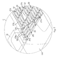
- the beveled fins 27a are provided with eyelets 27c which allow the cooling fluid to pass between the various pipes 29 and promote turbulence, as can also be seen in the detail C in fig. 1 , enlarged in fig. 2 .
- each circuit 26 The pipes 29 of each circuit 26 are disposed adjacent to each other and lie on a common plane.
- the entrance 29a and exit 29b of each pipe 29 is disposed adjacent and in close proximity, respectively, to the entrance 40a of the feed pipe 40 and the exit 42a of the discharge pipe 42, so that the cooling fluid entering from the feed pipe 40 is distributed uniformly in all the pipes 29, just as the exit from the pipes 29 occurs uniformly over the whole discharge pipe 42.
- the pipes 29 have a particular geometry that obliges the stream of cooling fluid to follow a pre-determined path, so that the fluid is distributed over the whole heat exchange surface.
- two sheets 21a, 21c are provided, respectively disposed in correspondence with the pipe 40 and the pipe 42, shaped as a rectangular trapezium, and a sheet 21b, disposed central to the previous two, shaped as an isosceles trapezium and having its oblique sides coinciding with the oblique sides of the sheets 21 a and 21 c.
- the inclination of the oblique sides can be varied, for example they can have an inclination of 30°, 45°, 60° or other.
- the pipes 29 are formed by a first portion 30, relating to the sheet 21a, disposed perpendicular to the direction S and directly connected to the feed pipe 40, a second portion 32, relating to the sheet 21b, disposed parallel to the direction S, and a third portion 34, relating to the sheet 21c, disposed perpendicular to the direction S and directly connected to the discharge pipe 42.
- the sense of the stream of cooling fluid in the portion 34 is the same direction and opposite sense with respect to the stream of cooling fluid in the portion 30, in the first case towards the wall 11f and in the second case in the opposite sense.
- the path of the cooling fluid is in this case indicated by the arrow R in figs. 1 and 2 .
- Double right angle geometry This type of disposition is called, here and hereafter, "double right angle geometry".
- double right angle geometry the cooling fluid that is fed by the pipe 40 immediately meets a plurality of pipes 29, and therefore is distributed uniformly through them, even at low flow rates. Afterwards, the cooling fluid is obliged to flow in each of the obligatory paths defined by the individual pipes 29, as far as the exit into the discharge pipe 42.
- the pre-cooling unit 20 is formed, on the air side, by five circuits 33, disposed between the walls 11a and 11b, structurally identical to the previous circuits 23.
- Each circuit 33 has respective channels 35 identical to the channels 24 and directly connected to them, which define, from the relative entrance 35a to the exit 35b, respective obligatory paths, so as to determine a continuous stream of air, in the direction S, from the entrance 12 to the exit 39 at the compartment 17. From a functional point of view, the circuits 33 allow the air to be cooled to pass from the entrance 12 into the pre-cooling unit 20 and in said direction S, to the subsequent cooling unit 22.
- Each circuit 33 and the respective channels 35 are connected without a break in continuity to the adjacent circuit 23 and the respective channels 24, in correspondence with the connection zone indicated by the reference number 37 in fig. 3 , so that the air flows, uniformly and along the same obligatory paths, from the entrance 12 to the exit 39.
- the circuit 33 therefore also distributes uniformly the stream of air from the entrance 14 through the channels 35, exploiting the whole heat exchange surface available.
- circuits 33 are disposed, vertically alternating, separated from the circuits 33 and fluidly communicating with each other.
- the circuits 33 and 44 are disposed in layers and define a packing or wafer.
- the circuits 44 are structurally identical to the circuits 26, that is, they are formed by fret-shaped sheets as described above which define pipes 46 ( figs. 1 and 5 ), identical to said pipes 29.
- the circuits 44 are able to allow the passage of the cooled air from the condensation separation unit 28 to the exit 14, passing through the pre-cooling unit 20.
- the pipes 46 of each circuit 44 determine obligatory paths for the cooled and de-humidified air, so as to receive, by means of their entrance 46a, the stream of cooled air directly that arrives through the aperture 31 from the condensation separation unit 28, allowing the uniform distribution thereof along obligatory paths, over the whole heat exchange surface, as far as the exit 46b, directly in proximity with the exit 14 of the cooled and de-humidified air.
- the whole heat exchange surface of the circuit 44 available is exploited, without determining preferential paths and dead zones.
- the disposition of the circuits 44 is inverted by 180°, with respect to an ideal median axis parallel to the direction S, to determine the correct path of the cooled and de-humidified air from the condensation separation unit 28 through the pre-cooling unit 20 to the exit 14.
- each pipe 46 comprises a first portion 48, directly connected to the aperture 31 of the condensation separation unit 28 and disposed perpendicular to the direction S, a second portion 50 disposed parallel to the direction S and a third portion 52, directly connected to the exit 14 and disposed perpendicular to the direction S.
- the cooled air arriving directly from the condensation separation unit 28 immediately meets a plurality of pipes 46 and hence is distributed uniformly through them, even at low flow rates. Afterwards, the cooled air is obliged to flow in each of the obligatory paths defined by the individual pipes 46, to the exit 14.
- the feed pipe 40 is disposed at a different height with respect to the discharge pipe 42, that is, with its exit 40a at a height greater than the respective entrance 42a of the discharge pipe 42. This is obtained by extending the discharge pipe 42 by a determinate length inside the heat exchange unit 22; in this way, it functions as a stopper, substantially preventing the discharge of the cooling fluid until the latter has reached a pre-determined height which corresponds to an optimum filling of all the circuits 26.
- the exit 40a of the feed pipe 40 is made in correspondence with a lower circuit 26b, disposed immediately above the lower circuit 23b, that is, about level H 0 ( fig. 4 ).
- the entrance 42a of the discharge pipe 42 is disposed in correspondence with an upper circuit 26a, disposed immediately above the third intermediate circuit 23c from below, at a height L, generally higher than H 0 and lower than level H 1 , in this case a little more than half the distance between H 0 and H 1 ( fig. 4 ).
- the pipes 29 are filled with the cooling fluid in an optimum manner, since the cooling fluid reaches the discharge pipe 42 only after the whole volume corresponding to the height L has been flooded.
- the condensation separation unit 28, downstream of a demister 36 conventionally disposed adjacent to the compartment 17, immediately after the stream of cooled air has been inverted also comprises an anti-drawing grid 38 to retain the humidity or condensation present in the cooled air.
- the grid 38 is formed by a holed plane, with an S-shaped section, that is, it comprises two plane portions disposed at heights staggered and connected to each other by an inclined step. The condensation falls due to gravity into a suitable condensation discharge 41.
- a horizontal separation surface for the condensation is also defined, represented by the grid 38.
- the condensation separation unit 28 is enclosed in a suitable box-shaped portion 28a of the frame of the exchanger 10.
- the stream of air Immediately after the grid 38, the stream of air, at this point cooled and de-humidified, performs a right-angled diversion and continues into the pre-cooling unit 20, distributing itself uniformly along all the pipes 46 described above, and following the relative obligatory path. From here, through an elbow-shaped compartment 19, defined by the collector 11e, the air exits from the exchanger 10 through the exit 14.
Landscapes
- Engineering & Computer Science (AREA)
- Physics & Mathematics (AREA)
- Thermal Sciences (AREA)
- Mechanical Engineering (AREA)
- General Engineering & Computer Science (AREA)
- Heat-Exchange Devices With Radiators And Conduit Assemblies (AREA)
Applications Claiming Priority (1)
| Application Number | Priority Date | Filing Date | Title |
|---|---|---|---|
| IT000025A ITUD20070025A1 (it) | 2007-02-07 | 2007-02-07 | Scambiatore di calore |
Publications (2)
| Publication Number | Publication Date |
|---|---|
| EP1956330A2 true EP1956330A2 (fr) | 2008-08-13 |
| EP1956330A3 EP1956330A3 (fr) | 2009-10-14 |
Family
ID=39357226
Family Applications (1)
| Application Number | Title | Priority Date | Filing Date |
|---|---|---|---|
| EP08151109A Withdrawn EP1956330A3 (fr) | 2007-02-07 | 2008-02-06 | Échangeur de chaleur |
Country Status (2)
| Country | Link |
|---|---|
| EP (1) | EP1956330A3 (fr) |
| IT (1) | ITUD20070025A1 (fr) |
Cited By (4)
| Publication number | Priority date | Publication date | Assignee | Title |
|---|---|---|---|---|
| WO2011047874A1 (fr) * | 2009-10-23 | 2011-04-28 | Voith Patent Gmbh | Plaque d'échange de chaleur et évaporateur d'une telle plaque |
| ITPN20110037A1 (it) * | 2011-05-20 | 2012-11-21 | Maurizio Nardini | Apparato e procedimento perfezionato per il raffreddamento, deumidificazione e riscaldamento di un flusso di gas |
| ITUD20120060A1 (it) * | 2012-04-13 | 2013-10-14 | Ohg Ind S R L Con Unico | Scambiatore di calore |
| CN103673665A (zh) * | 2013-11-30 | 2014-03-26 | 无锡金玺换热器有限公司 | 螺杆机用模块式换热器 |
Family Cites Families (9)
| Publication number | Priority date | Publication date | Assignee | Title |
|---|---|---|---|---|
| US3313344A (en) * | 1965-05-11 | 1967-04-11 | Gen Motors Corp | Plate fin heat exchanger with curved expansion tubes |
| US3860065A (en) * | 1970-04-08 | 1975-01-14 | Trane Co | Distributor for plate type heat exchanger having side headers |
| CA929929A (en) * | 1970-04-08 | 1973-07-10 | Trane Company Of Canada Limited | Distributor for plate type heat exchangers having side headers |
| JPH0711325Y2 (ja) * | 1987-12-24 | 1995-03-15 | 住友精密工業株式会社 | プレートフィン型熱交換器 |
| JP2814765B2 (ja) * | 1991-04-12 | 1998-10-27 | 三菱電機株式会社 | 熱交換器 |
| DE4118289A1 (de) * | 1991-06-04 | 1992-12-10 | Autokuehler Gmbh & Co Kg | Waermetauscher-vorrichtung fuer kaeltetrockner an druckluftanlagen |
| FR2685071B1 (fr) * | 1991-12-11 | 1996-12-13 | Air Liquide | Echangeur de chaleur indirect du type a plaques. |
| DE10249834A1 (de) * | 2002-10-21 | 2004-04-29 | Autokühler GmbH & Co. KG | Vorrichtung zur Abkühlung und Trocknung von Luft, insbesondere für Kältemitteltrockner von Druckluftanlagen |
| ITMI20040926A1 (it) * | 2004-05-07 | 2004-08-07 | Domnick Hunter Hiross S P A | Essicatore di gas compresso a refrigerazione |
-
2007
- 2007-02-07 IT IT000025A patent/ITUD20070025A1/it unknown
-
2008
- 2008-02-06 EP EP08151109A patent/EP1956330A3/fr not_active Withdrawn
Non-Patent Citations (1)
| Title |
|---|
| None * |
Cited By (6)
| Publication number | Priority date | Publication date | Assignee | Title |
|---|---|---|---|---|
| WO2011047874A1 (fr) * | 2009-10-23 | 2011-04-28 | Voith Patent Gmbh | Plaque d'échange de chaleur et évaporateur d'une telle plaque |
| US8793987B2 (en) | 2009-10-23 | 2014-08-05 | Steamdrive Gmbh | Heat exchanger plate and an evaporator with such a plate |
| ITPN20110037A1 (it) * | 2011-05-20 | 2012-11-21 | Maurizio Nardini | Apparato e procedimento perfezionato per il raffreddamento, deumidificazione e riscaldamento di un flusso di gas |
| ITUD20120060A1 (it) * | 2012-04-13 | 2013-10-14 | Ohg Ind S R L Con Unico | Scambiatore di calore |
| EP2650634A1 (fr) | 2012-04-13 | 2013-10-16 | Officine Meccaniche Industriali SRL Con Unico Socio | Échangeur de chaleur |
| CN103673665A (zh) * | 2013-11-30 | 2014-03-26 | 无锡金玺换热器有限公司 | 螺杆机用模块式换热器 |
Also Published As
| Publication number | Publication date |
|---|---|
| EP1956330A3 (fr) | 2009-10-14 |
| ITUD20070025A1 (it) | 2008-08-08 |
Similar Documents
| Publication | Publication Date | Title |
|---|---|---|
| KR102231142B1 (ko) | 열교환 판 및 열교환기 | |
| KR102227068B1 (ko) | 열교환 판 및 열교환기 | |
| KR102268484B1 (ko) | 열교환기 | |
| JP5901748B2 (ja) | 冷媒分配器、この冷媒分配器を備えた熱交換器、冷凍サイクル装置及び空気調和機 | |
| US9494368B2 (en) | Heat exchanger and air conditioner | |
| KR102589420B1 (ko) | 열 교환기 및 열 교환 모듈 | |
| US20130269910A1 (en) | Heat exchanger | |
| EP3183528A1 (fr) | Échangeur de chaleur à micro-canal à faible charge de réfrigérant | |
| KR20180029730A (ko) | 열교환기 | |
| KR102170312B1 (ko) | 열교환기 | |
| US4121656A (en) | Header | |
| SE525354C2 (sv) | Värmeväxlaranordning och plattpaket | |
| JP6554182B2 (ja) | 重ねられた複数のプレートを有する熱交換器 | |
| EP4067800A1 (fr) | Échangeur de chaleur | |
| CN103403484B (zh) | 用于处理气体的装置 | |
| JP5338950B2 (ja) | 熱交換器 | |
| CN105716440B (zh) | 一种具有气液分离功能的板式冷凝器 | |
| JP2002081797A (ja) | 凝縮器 | |
| KR20130025516A (ko) | 격벽이 구비된 판형 열교환기 | |
| KR102232165B1 (ko) | 액체상을 배출하기 위한 수집 채널을 갖는 열 교환기 | |
| JP2006234347A (ja) | 冷媒分流器および該冷媒分流器を用いた冷凍装置 | |
| KR102568753B1 (ko) | 열교환기 | |
| JPH04263793A (ja) | 熱交換器 | |
| JP7480183B2 (ja) | プレート熱交換器、熱交換プレートおよび海水などのフィードを処理する方法 | |
| JP2009034608A (ja) | 凝縮装置 |
Legal Events
| Date | Code | Title | Description |
|---|---|---|---|
| PUAI | Public reference made under article 153(3) epc to a published international application that has entered the european phase |
Free format text: ORIGINAL CODE: 0009012 |
|
| AK | Designated contracting states |
Kind code of ref document: A2 Designated state(s): AT BE BG CH CY CZ DE DK EE ES FI FR GB GR HR HU IE IS IT LI LT LU LV MC MT NL NO PL PT RO SE SI SK TR |
|
| AX | Request for extension of the european patent |
Extension state: AL BA MK RS |
|
| PUAL | Search report despatched |
Free format text: ORIGINAL CODE: 0009013 |
|
| AK | Designated contracting states |
Kind code of ref document: A3 Designated state(s): AT BE BG CH CY CZ DE DK EE ES FI FR GB GR HR HU IE IS IT LI LT LU LV MC MT NL NO PL PT RO SE SI SK TR |
|
| AX | Request for extension of the european patent |
Extension state: AL BA MK RS |
|
| 17P | Request for examination filed |
Effective date: 20100413 |
|
| AKX | Designation fees paid |
Designated state(s): AT BE BG CH CY CZ DE DK EE ES FI FR GB GR HR HU IE IS IT LI LT LU LV MC MT NL NO PL PT RO SE SI SK TR |
|
| 17Q | First examination report despatched |
Effective date: 20170203 |
|
| STAA | Information on the status of an ep patent application or granted ep patent |
Free format text: STATUS: THE APPLICATION IS DEEMED TO BE WITHDRAWN |
|
| 18D | Application deemed to be withdrawn |
Effective date: 20170815 |