EP1958720A2 - Découpeuse de clés et procédé - Google Patents
Découpeuse de clés et procédé Download PDFInfo
- Publication number
- EP1958720A2 EP1958720A2 EP08009489A EP08009489A EP1958720A2 EP 1958720 A2 EP1958720 A2 EP 1958720A2 EP 08009489 A EP08009489 A EP 08009489A EP 08009489 A EP08009489 A EP 08009489A EP 1958720 A2 EP1958720 A2 EP 1958720A2
- Authority
- EP
- European Patent Office
- Prior art keywords
- key
- cutting
- cutting machine
- clamp
- block
- Prior art date
- Legal status (The legal status is an assumption and is not a legal conclusion. Google has not performed a legal analysis and makes no representation as to the accuracy of the status listed.)
- Granted
Links
Images









Classifications
-
- B—PERFORMING OPERATIONS; TRANSPORTING
- B23—MACHINE TOOLS; METAL-WORKING NOT OTHERWISE PROVIDED FOR
- B23C—MILLING
- B23C3/00—Milling particular work; Special milling operations; Machines therefor
-
- B—PERFORMING OPERATIONS; TRANSPORTING
- B23—MACHINE TOOLS; METAL-WORKING NOT OTHERWISE PROVIDED FOR
- B23C—MILLING
- B23C3/00—Milling particular work; Special milling operations; Machines therefor
- B23C3/28—Grooving workpieces
- B23C3/35—Milling grooves in keys
-
- B—PERFORMING OPERATIONS; TRANSPORTING
- B23—MACHINE TOOLS; METAL-WORKING NOT OTHERWISE PROVIDED FOR
- B23C—MILLING
- B23C2235/00—Details of milling keys
- B23C2235/28—Key blanks
-
- Y—GENERAL TAGGING OF NEW TECHNOLOGICAL DEVELOPMENTS; GENERAL TAGGING OF CROSS-SECTIONAL TECHNOLOGIES SPANNING OVER SEVERAL SECTIONS OF THE IPC; TECHNICAL SUBJECTS COVERED BY FORMER USPC CROSS-REFERENCE ART COLLECTIONS [XRACs] AND DIGESTS
- Y10—TECHNICAL SUBJECTS COVERED BY FORMER USPC
- Y10T—TECHNICAL SUBJECTS COVERED BY FORMER US CLASSIFICATION
- Y10T409/00—Gear cutting, milling, or planing
- Y10T409/30—Milling
- Y10T409/30084—Milling with regulation of operation by templet, card, or other replaceable information supply
- Y10T409/300952—Milling with regulation of operation by templet, card, or other replaceable information supply to cut lock key
-
- Y—GENERAL TAGGING OF NEW TECHNOLOGICAL DEVELOPMENTS; GENERAL TAGGING OF CROSS-SECTIONAL TECHNOLOGIES SPANNING OVER SEVERAL SECTIONS OF THE IPC; TECHNICAL SUBJECTS COVERED BY FORMER USPC CROSS-REFERENCE ART COLLECTIONS [XRACs] AND DIGESTS
- Y10—TECHNICAL SUBJECTS COVERED BY FORMER USPC
- Y10T—TECHNICAL SUBJECTS COVERED BY FORMER US CLASSIFICATION
- Y10T409/00—Gear cutting, milling, or planing
- Y10T409/30—Milling
- Y10T409/30084—Milling with regulation of operation by templet, card, or other replaceable information supply
- Y10T409/300952—Milling with regulation of operation by templet, card, or other replaceable information supply to cut lock key
- Y10T409/301008—Using templet other than a key
-
- Y—GENERAL TAGGING OF NEW TECHNOLOGICAL DEVELOPMENTS; GENERAL TAGGING OF CROSS-SECTIONAL TECHNOLOGIES SPANNING OVER SEVERAL SECTIONS OF THE IPC; TECHNICAL SUBJECTS COVERED BY FORMER USPC CROSS-REFERENCE ART COLLECTIONS [XRACs] AND DIGESTS
- Y10—TECHNICAL SUBJECTS COVERED BY FORMER USPC
- Y10T—TECHNICAL SUBJECTS COVERED BY FORMER US CLASSIFICATION
- Y10T409/00—Gear cutting, milling, or planing
- Y10T409/30—Milling
- Y10T409/30084—Milling with regulation of operation by templet, card, or other replaceable information supply
- Y10T409/30112—Process
-
- Y—GENERAL TAGGING OF NEW TECHNOLOGICAL DEVELOPMENTS; GENERAL TAGGING OF CROSS-SECTIONAL TECHNOLOGIES SPANNING OVER SEVERAL SECTIONS OF THE IPC; TECHNICAL SUBJECTS COVERED BY FORMER USPC CROSS-REFERENCE ART COLLECTIONS [XRACs] AND DIGESTS
- Y10—TECHNICAL SUBJECTS COVERED BY FORMER USPC
- Y10T—TECHNICAL SUBJECTS COVERED BY FORMER US CLASSIFICATION
- Y10T409/00—Gear cutting, milling, or planing
- Y10T409/30—Milling
- Y10T409/30084—Milling with regulation of operation by templet, card, or other replaceable information supply
- Y10T409/301176—Reproducing means
- Y10T409/301624—Duplicating means
- Y10T409/30168—Duplicating means with means for operation without manual intervention
- Y10T409/302352—Duplicating means with means for operation without manual intervention including plural cutters
-
- Y—GENERAL TAGGING OF NEW TECHNOLOGICAL DEVELOPMENTS; GENERAL TAGGING OF CROSS-SECTIONAL TECHNOLOGIES SPANNING OVER SEVERAL SECTIONS OF THE IPC; TECHNICAL SUBJECTS COVERED BY FORMER USPC CROSS-REFERENCE ART COLLECTIONS [XRACs] AND DIGESTS
- Y10—TECHNICAL SUBJECTS COVERED BY FORMER USPC
- Y10T—TECHNICAL SUBJECTS COVERED BY FORMER US CLASSIFICATION
- Y10T409/00—Gear cutting, milling, or planing
- Y10T409/30—Milling
- Y10T409/30084—Milling with regulation of operation by templet, card, or other replaceable information supply
- Y10T409/301176—Reproducing means
- Y10T409/301624—Duplicating means
- Y10T409/302464—Duplicating means including plural cutters
-
- Y—GENERAL TAGGING OF NEW TECHNOLOGICAL DEVELOPMENTS; GENERAL TAGGING OF CROSS-SECTIONAL TECHNOLOGIES SPANNING OVER SEVERAL SECTIONS OF THE IPC; TECHNICAL SUBJECTS COVERED BY FORMER USPC CROSS-REFERENCE ART COLLECTIONS [XRACs] AND DIGESTS
- Y10—TECHNICAL SUBJECTS COVERED BY FORMER USPC
- Y10T—TECHNICAL SUBJECTS COVERED BY FORMER US CLASSIFICATION
- Y10T409/00—Gear cutting, milling, or planing
- Y10T409/30—Milling
- Y10T409/303752—Process
- Y10T409/303808—Process including infeeding
-
- Y—GENERAL TAGGING OF NEW TECHNOLOGICAL DEVELOPMENTS; GENERAL TAGGING OF CROSS-SECTIONAL TECHNOLOGIES SPANNING OVER SEVERAL SECTIONS OF THE IPC; TECHNICAL SUBJECTS COVERED BY FORMER USPC CROSS-REFERENCE ART COLLECTIONS [XRACs] AND DIGESTS
- Y10—TECHNICAL SUBJECTS COVERED BY FORMER USPC
- Y10T—TECHNICAL SUBJECTS COVERED BY FORMER US CLASSIFICATION
- Y10T409/00—Gear cutting, milling, or planing
- Y10T409/30—Milling
- Y10T409/30392—Milling with means to protect operative or machine [e.g., guard, safety device, etc.]
-
- Y—GENERAL TAGGING OF NEW TECHNOLOGICAL DEVELOPMENTS; GENERAL TAGGING OF CROSS-SECTIONAL TECHNOLOGIES SPANNING OVER SEVERAL SECTIONS OF THE IPC; TECHNICAL SUBJECTS COVERED BY FORMER USPC CROSS-REFERENCE ART COLLECTIONS [XRACs] AND DIGESTS
- Y10—TECHNICAL SUBJECTS COVERED BY FORMER USPC
- Y10T—TECHNICAL SUBJECTS COVERED BY FORMER US CLASSIFICATION
- Y10T409/00—Gear cutting, milling, or planing
- Y10T409/30—Milling
- Y10T409/304088—Milling with means to remove chip
-
- Y—GENERAL TAGGING OF NEW TECHNOLOGICAL DEVELOPMENTS; GENERAL TAGGING OF CROSS-SECTIONAL TECHNOLOGIES SPANNING OVER SEVERAL SECTIONS OF THE IPC; TECHNICAL SUBJECTS COVERED BY FORMER USPC CROSS-REFERENCE ART COLLECTIONS [XRACs] AND DIGESTS
- Y10—TECHNICAL SUBJECTS COVERED BY FORMER USPC
- Y10T—TECHNICAL SUBJECTS COVERED BY FORMER US CLASSIFICATION
- Y10T409/00—Gear cutting, milling, or planing
- Y10T409/30—Milling
- Y10T409/306664—Milling including means to infeed rotary cutter toward work
- Y10T409/306776—Axially
- Y10T409/307168—Plural cutters
-
- Y—GENERAL TAGGING OF NEW TECHNOLOGICAL DEVELOPMENTS; GENERAL TAGGING OF CROSS-SECTIONAL TECHNOLOGIES SPANNING OVER SEVERAL SECTIONS OF THE IPC; TECHNICAL SUBJECTS COVERED BY FORMER USPC CROSS-REFERENCE ART COLLECTIONS [XRACs] AND DIGESTS
- Y10—TECHNICAL SUBJECTS COVERED BY FORMER USPC
- Y10T—TECHNICAL SUBJECTS COVERED BY FORMER US CLASSIFICATION
- Y10T409/00—Gear cutting, milling, or planing
- Y10T409/30—Milling
- Y10T409/306664—Milling including means to infeed rotary cutter toward work
- Y10T409/307448—Milling including means to infeed rotary cutter toward work with work holder
-
- Y—GENERAL TAGGING OF NEW TECHNOLOGICAL DEVELOPMENTS; GENERAL TAGGING OF CROSS-SECTIONAL TECHNOLOGIES SPANNING OVER SEVERAL SECTIONS OF THE IPC; TECHNICAL SUBJECTS COVERED BY FORMER USPC CROSS-REFERENCE ART COLLECTIONS [XRACs] AND DIGESTS
- Y10—TECHNICAL SUBJECTS COVERED BY FORMER USPC
- Y10T—TECHNICAL SUBJECTS COVERED BY FORMER US CLASSIFICATION
- Y10T409/00—Gear cutting, milling, or planing
- Y10T409/30—Milling
- Y10T409/30784—Milling including means to adustably position cutter
- Y10T409/307952—Linear adjustment
- Y10T409/308176—Linear adjustment with position indicator or limit means
-
- Y—GENERAL TAGGING OF NEW TECHNOLOGICAL DEVELOPMENTS; GENERAL TAGGING OF CROSS-SECTIONAL TECHNOLOGIES SPANNING OVER SEVERAL SECTIONS OF THE IPC; TECHNICAL SUBJECTS COVERED BY FORMER USPC CROSS-REFERENCE ART COLLECTIONS [XRACs] AND DIGESTS
- Y10—TECHNICAL SUBJECTS COVERED BY FORMER USPC
- Y10T—TECHNICAL SUBJECTS COVERED BY FORMER US CLASSIFICATION
- Y10T409/00—Gear cutting, milling, or planing
- Y10T409/30—Milling
- Y10T409/30784—Milling including means to adustably position cutter
- Y10T409/307952—Linear adjustment
- Y10T409/308288—Linear adjustment including gantry-type cutter-carrier
-
- Y—GENERAL TAGGING OF NEW TECHNOLOGICAL DEVELOPMENTS; GENERAL TAGGING OF CROSS-SECTIONAL TECHNOLOGIES SPANNING OVER SEVERAL SECTIONS OF THE IPC; TECHNICAL SUBJECTS COVERED BY FORMER USPC CROSS-REFERENCE ART COLLECTIONS [XRACs] AND DIGESTS
- Y10—TECHNICAL SUBJECTS COVERED BY FORMER USPC
- Y10T—TECHNICAL SUBJECTS COVERED BY FORMER US CLASSIFICATION
- Y10T409/00—Gear cutting, milling, or planing
- Y10T409/30—Milling
- Y10T409/30784—Milling including means to adustably position cutter
- Y10T409/307952—Linear adjustment
- Y10T409/308344—Plural cutters
-
- Y—GENERAL TAGGING OF NEW TECHNOLOGICAL DEVELOPMENTS; GENERAL TAGGING OF CROSS-SECTIONAL TECHNOLOGIES SPANNING OVER SEVERAL SECTIONS OF THE IPC; TECHNICAL SUBJECTS COVERED BY FORMER USPC CROSS-REFERENCE ART COLLECTIONS [XRACs] AND DIGESTS
- Y10—TECHNICAL SUBJECTS COVERED BY FORMER USPC
- Y10T—TECHNICAL SUBJECTS COVERED BY FORMER US CLASSIFICATION
- Y10T409/00—Gear cutting, milling, or planing
- Y10T409/30—Milling
- Y10T409/30784—Milling including means to adustably position cutter
- Y10T409/3084—Milling including means to adustably position cutter with position indicator or limit means
-
- Y—GENERAL TAGGING OF NEW TECHNOLOGICAL DEVELOPMENTS; GENERAL TAGGING OF CROSS-SECTIONAL TECHNOLOGIES SPANNING OVER SEVERAL SECTIONS OF THE IPC; TECHNICAL SUBJECTS COVERED BY FORMER USPC CROSS-REFERENCE ART COLLECTIONS [XRACs] AND DIGESTS
- Y10—TECHNICAL SUBJECTS COVERED BY FORMER USPC
- Y10T—TECHNICAL SUBJECTS COVERED BY FORMER US CLASSIFICATION
- Y10T409/00—Gear cutting, milling, or planing
- Y10T409/30—Milling
- Y10T409/308624—Milling with limit means to aid in positioning of cutter bit or work [e.g., gauge, stop, etc.]
-
- Y—GENERAL TAGGING OF NEW TECHNOLOGICAL DEVELOPMENTS; GENERAL TAGGING OF CROSS-SECTIONAL TECHNOLOGIES SPANNING OVER SEVERAL SECTIONS OF THE IPC; TECHNICAL SUBJECTS COVERED BY FORMER USPC CROSS-REFERENCE ART COLLECTIONS [XRACs] AND DIGESTS
- Y10—TECHNICAL SUBJECTS COVERED BY FORMER USPC
- Y10T—TECHNICAL SUBJECTS COVERED BY FORMER US CLASSIFICATION
- Y10T409/00—Gear cutting, milling, or planing
- Y10T409/30—Milling
- Y10T409/30868—Work support
- Y10T409/309016—Work support with work holder or guide
Definitions
- This invention generally relates to key cutting machines and related methods. More particularly, the present invention relates to a key cutting machine that has improved alignment, clamping, and cutting mechanisms and to a related method for cutting a notch pattern on a key blank.
- Key duplication systems exist that cut biting patterns in blank keys by tracing the original key to be duplicated or by using a code or extracting the biting patterns from a database.
- the former type is more prevalent in consumer outlets and the latter is more prevalent in businesses such as automobile dealers and rental agencies.
- a key cutting machine described in U.S. Patent No. 5,676,504 utilizes a set of cassettes to address the need for proper alignment and clamping of a key.
- the cassettes may be selectively inserted into an cassette receiving aperture of the key cutting machine and provide both positional alignment function and clamping function while the key cutting machine cuts a bit notch pattern on a key blank.
- the key cutting machine described in '504 requires an operator to select different cassettes for different key blanks and different bit notch patterns.
- the present invention is directed to an improved key cutting machine and a related method.
- the advantages and purposes of the invention will be set forth in part in the description which follows, and in part will be obvious from the description, or may be learned by practice of the invention.
- the advantages and purposes of the invention will be realized and attained by the elements and combinations particularly pointed out in the appended claims.
- a key cutting machine comprises a pair of cutting heads and a clamp mechanism.
- Each cutting head includes a cutting wheel having an edge.
- An alignment structure is mounted behind each cutting wheel.
- Each alignment structure has a key guide portion aligned tangent to the edge of a corresponding cutting wheel to engage and position a key blank laterally.
- the clamp mechanism is positioned between the cutting heads and is configured to hold the key blank stationary.
- the invention is directed to a key cutting machine for cutting a notch pattern on a key blank.
- the key cutting machine comprises a housing and a pair of cutting heads.
- the housing includes a top frame and a base.
- the cutting heads are suspended below the top frame of the housing without being supported on the base of the housing.
- Each cutting head includes a cutting wheel rotatable to cut the notch pattern on the key blank.
- the invention is directed to a key cutting machine for cutting a notch pattern on a key blank.
- the key cutting machine comprises a housing, a pair of cutting heads, and a clamp mechanism.
- the housing includes a top frame.
- the cutting heads are positioned within the housing.
- Each cutting head includes a cutting wheel rotatable to cut the notch pattern on the key blank.
- the clamp mechanism is positioned between the cutting heads.
- the clamp mechanism includes a lower clamp and an upper clamp. The upper clamp is suspended from the top frame of the housing and is vertically movable relative to the lower clamp to hold the key blank stationary.
- the invention is directed to a key cutting machine for cutting a notch pattern on a key blank.
- the key cutting machine comprises a clamp mechanism, a tip stop mechanism, and a pair of cutting heads.
- the clamp mechanism is configured to hold the key blank stationary.
- the tip stop mechanism is positioned behind the clamp mechanism and is configured to engage a tip of the key blank and position the key blank longitudinally.
- the cutting heads are movable relative to the clamp mechanism.
- the cutting heads are movable longitudinally in unison and are movable independently of each other laterally.
- Each cutting head includes a cutting wheel rotatable to cut the notch pattern on the key blank.
- the invention is directed to a method for cutting a notch pattern on a key blank using a key cutting machine.
- the key cutting machine includes a clamp mechanism, a tip stop, and a pair of cutting heads.
- Each cutting head includes a cutting wheel and a paddle mounted behind the cutting wheel.
- the method comprises the steps of: moving the cutting heads laterally to position the paddles at correct lateral positions spaced apart from each other by a width of the key blank; inserting the key blank into the clamp mechanism; positioning the key blank laterally by engaging the key blank with the paddles; engaging a tip of the key blank with the tip stop; positioning the key blank at a correct longitudinal position by moving the tip stop longitudinally; clamping the key blank stationary using the clamp mechanism; and moving at least one of the cutting heads relative to the clamp mechanism to cut the notch pattern on the key blank.
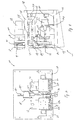
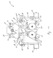
- Fig. 1 is a front view of an embodiment of a key cutting machine according to the present invention
- Fig. 2 is a side view of the key cutting machine of Fig. 1 ;
- Fig. 3 is a front view of a key cutting machine as shown in Fig. 1 illustrating a vertical center line;
- Fig. 4 is a section view of a key cutting machine taken along line B-B of Fig. 3 illustrating a clamp mechanism and a tip stop mechanism;
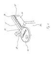
- Fig. 5 is a partial perspective view of a key cutting machine according to the present invention illustrating alignment paddles pivotally mounted to cutting heads;
- Fig. 6 is an enlarged perspective view of the portion of a key cutting machine enclosed in circle A of Fig. 5 ;
- Fig. 7 is a top view of a key cutting machine according to the present invention illustrating a tip stop mechanism
- Fig. 8 is a side view of a cutting machine according to the present invention illustrating a tip stop mechanism
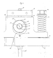
- Fig. 9 is a partial front view of the top of a clamp mechanism illustrating a closed position of the clamp
- Fig. 10 is a partial front view of a clamp mechanism illustrating an open position of the clamp
- Fig. 11 is a perspective view of a key and an anvil
- Fig. 12 is a is a section view of a key cutting machine taken along line A-A of Fig. 13 ;
- Fig. 13 is a rear view of a key cutting machine according to the present invention.
- Fig. 14 is a front view of a key cutting machine according to the present invention illustrating a threaded shaft of a stepper motor for lateral movements;
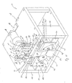
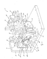
- Fig. 15 is a perspective view of a key cutting machine according to the present invention.
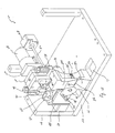
- Fig. 16 is a partial perspective view of a key cutting machine according to the present invention where a top frame is removed from Fig. 15 ;
- Fig. 17 is a partial perspective view of a key cutting machine according to the present invention illustrating linear bearings and a top portion of a suspension bracket;
- Fig. 18 is a partial perspective view of a key cutting machine according to the present invention illustrating an upper clamp and an anvil;
- Fig. 19 is a partial perspective view of the top of a clamp mechanism illustrating a shaft and a cam
- Fig. 20 is a partial perspective view of the top of a clamp mechanism illustrating a block biased by springs
- Fig. 21 is a partial perspective view of another embodiment of a key cutting machine according to the present invention.
- Fig. 22 is a partial front view of the key cutting machine of Fig. 21 illustrating pivot arms
- Fig. 23 is a partial bottom view of the key cutting machine of Fig. 21 illustrating a push block and a spring.
- An exemplary embodiment of a key cutting machine of the present invention is designated generally by reference number 20.
- key cutting machine 20 includes a housing having a top frame 24 that is supported by a pair of side frames 26.
- a pair of suspension blocks 30 are connected to the front of top frame 24 and a pair of suspension blocks 30 are connected to the back of top frame 24.
- Each suspension block 30 includes an opening 32 to receive and hold a guide rail 34.
- a pair of linear bearings 36, each supported by bearing support 38, are slidably mounted on each guide rail 34 ( Figs. 5 , 16 , and 17 ).
- Bearing supports 38 are mounted to a carriage or suspension bracket 40 at the top portion 42 thereof ( Figs. 1 and 14-17 ).
- a pair of cutting heads 28 are suspended from top portion 42 of suspension bracket 40.
- Each cutting head 28 includes a cutting wheel 29 rotated by a drive motor 31 for cutting a notch pattern on a key blank 33.
- drive motors 31 preferably rotate cutting wheels 29 in the directions designated by reference number 35 to direct the majority of cutting chips toward a base 23 of key cutting machine 20 and away from linear bearings 36 and other cutting components.
- base 23 includes openings 21 ( Figs. 5 and 15-18 ) for cutting chips to fall through.
- a tray (not shown) may be positioned below openings 21 to collect cutting chips.
- both cutting heads 28 are suspended from top portion 42 of suspension bracket 40.
- top portion 42 of suspension bracket 40 is common to both cutting heads 28. Accordingly, both cutting heads 28 move longitudinally in unison as suspension bracket 40 moves along guide rails 34 in longitudinal directions designated by reference number 46 ( Figs. 2 , 4 , and 17 ).
- a stepper motor 48 controls the longitudinal movement of cutting heads 28. As shown in Figs. 4 and 15 , stepper motor 48 is suspended from top frame 24. A threaded shaft 50 extends through stepper motor 48 and one end thereof is connected to a block 54 supported on the upper surface of top portion 42 of suspension bracket 40. As illustrated in Fig. 4 , a pin 52 connects threaded shaft 50 to block 54. However, other known techniques may be used to connect threaded shaft 50 to block 54. As the motor armature (not shown) of stepper motor 48 rotates in a first direction, threaded shaft 50 moves toward the back of key cutting machine 20 and carries with it suspension bracket 40. Consequently, both cutting heads 28 move longitudinally in unison toward the back of key cutting machine 20. Similarly, both cutting heads 28 move in unison toward the front of key cutting machine 20 as the motor armature of stepper motor 48 rotates in a second direction opposite to the first direction.
- each cutting head 28 has a dove-tail shaped projection 72 protruding from the top surface thereof.
- Dove-tail shaped projection 72 of each cutting head 28 slidably engages a correspondingly-shaped groove 74 formed in a block 70 suspended from top portion 42 of suspension bracket 40.
- Fig. 5 omits top portion 42 of suspension bracket 40 in order to show a tip stop mechanism 170 explained in greater detail below.
- the present invention contemplates the use of different shapes for projections 72 and grooves 74.
- the present invention contemplates the use of grooves 74 on cutting heads 28 and corresponding projections 72 on blocks 70.
- a stepper motor 60 is mounted to each side portion 44 of suspension bracket 40. Accordingly, stepper motor 60 moves longitudinally with suspension bracket 40 as indicated by arrow 46 in Fig. 2 .
- a threaded shaft 62 ( Figs. 7 and 14 ) extends through side portion 44 of suspension bracket 40 and is connected to a block 64 protruding from the front surface of each cutting head 28. Similar to threaded shaft 50, threaded shaft 62 moves linearly as the motor armature (not shown) of stepper motor 60 rotates in first and second directions. Through the connection to block 64, threaded shaft 62 pushes or pulls cutting head 28. In response to the linear movements of threaded shaft 62, cutting head 28 moves by sliding dove-tail shaped projection 72 in groove 74.
- Clamp mechanism 80 While cutting heads 28 move longitudinally and laterally to cut a desired notch pattern on key blank 33, a clamp mechanism 80 holds key blank 33 stationary.
- Clamp mechanism 80 includes a lower clamp or anvil 82 and an upper clamp 84.
- Anvil 82 is supported on base 23 and includes a recess 86 formed on the top portion thereof as shown in Fig. 6 .
- Anvil 82 further includes a pair of pins 88 protruding from the top portion thereof toward top frame 24.
- Upper clamp 84 includes a pair of holes (not shown) that correspond to and engage pins 88.
- Upper clamp 84 is movable vertically to and away from anvil 82. Pins 88 ensure upper clamp 84 moves in a substantially vertical direction.
- anvil 82 includes an elongated portion 83 configured to support a blade portion 35 of key blank 33.
- Elongated portion 83 is positioned at the lateral center of anvil 82 behind recess 86.
- Elongated portion 83 has a length to support the entire length of blade portion 35 of key blank 33 and a width narrower than the width of blade portion 35 of key blank 33.
- the top of elongated portion 83 is coplanar with the bottom of recess 86.
- upper clamp 84 includes a corresponding elongated portion 85 ( Figs. 4 and 18 ) configured to press down on blade portion 35 of key blank 33.
- Elongated portions 83 and 85 provide support for the cutting area of blade portion 35 to minimize the rotational leverage (i.e., torque) applied to key blank 33 by cutting wheels 29.
- clamping mechanism 80 does not engage the handle of key blank 33.
- the clamp does not have to account for keys where the handle thickness is different than the blade thickness, as is the case with plastic handled key.
- the bottom of recess 86 and elongated portion 83 combine to form a T-shaped supporting surface.
- the bottom surface 95 ( Figs. 1 and 18 ) of upper clamp 84 and elongated portion 85 combine to form a T-shaped pressing surface.
- the bottom of recess 86 and the bottom surface 95 of upper clamp 84 are configured to support and press the entire width of a shank portion 39 of key blank 33. By supporting and pressing the entire width of shank portion 39, the bottom of recess 86 and the bottom surface 95 prevent key blank 33 from tilting even if elongated portions 83 and 85 engage a groove 41 or other uneven milling surfaces.
- clamp mechanism 80 To move upper clamp 84 to and away from anvil 82, clamp mechanism 80 utilizes a cam 90 and springs 92. As illustrated in Figs. 3, 4 , 15 , 19 , and 20 , clamp mechanism 80 include a support block 100 secured to top frame 24 and a block 98 shaped like an upside down T. Support block 100 includes an elongated recess 102 and a hole 104 extending through the top portion 101 thereof. Block 98 includes a pin 99 protruding from the top portion 97 thereof. Block 98 is positioned in elongated recess 102 of support block 100.
- the height of elongated recess 102 is greater than that of block 98 so that block 98 is movable vertically between top portion 101 of support block 100 and the upper surface of top frame 24. Pin 99 received through hole 104 of support block 100 guides the vertical movements of block 98.
- block 98 includes holes 106 configured to receive bolts 91 therethrough. Bolts 91 received though holes 106 of block 98 are secured to top frame 24. Block 98 is connected to a clamp screw 94 extending through a hole 96 in top frame 24. Clamp screw 94 in turn is connected to upper clamp 84. Springs 92, secured by bolts 91, exert a downward biasing force on block 98, and therefore, on clamp screw 94. The spring force acts on block 98 to move upper clamp 84 toward anvil 82 and into a closed position. Depending on the thickness of key blank 33, the precise position of the bottom surface 95 of upper clamp 84 in a closed position varies. Springs 92, however, provides a sufficient downward force to hold key blank 33 stationary regardless of the precise position of the bottom surface 95 of upper clamp 84.
- clamp mechanism 80 utilizes cam 90 and a shaft 110.
- Shaft 110 extends parallel to top frame 24 through holes 112 of support block 100 and a hole 114 of block 98.
- Bearings 116 mounted in holes 112 of support block 100 rotatably support shaft 110.
- Shaft 110 is rotated by a DC motor 118.
- DC motor 118 is mounted to a block 120 extending from top frame 24 and includes a rotary shaft 122 coupled to shaft 110 by a coupler 124.
- cam 90 is mounted on an eccentric portion 111 of shaft 110 and rotates with shaft 110.
- Cam 90 is press-fitted onto eccentric portion 111 of shaft 110 so that the center 125 of cam 90 is offset from the rotational axis 123 of shaft 110. Accordingly, a portion 132 is positioned farther away from rotational axis 123 of shaft 110 than a portion 130.
- cam 90 includes a roller bearing 127 so that it rolls rather than slides against the inner surface of opening 114.
- portion 132 of cam 90 contacts the upper surface of opening 114.
- the contact between portion 132 of cam 90 and the upper surface of opening 114 then overcomes the downward biasing force exerted by springs 92 and moves block 98 toward upper portion 101 of supporting block 100.
- block 98 moves toward upper portion 101 of support block 100, it pulls clamp screw 94 upward.
- Clamp screw 94 in turn pulls upper clamp 84 upward to release key blank 33.
- cam 90 is circular in shape.
- cam 90 may assume many different shapes, including but not limited to ellipses, ovals, or any combination thereof, as long as the distances between rotational axis 123 of shaft 110 and portions 130 and 132 are different.
- shaft 110 instead of eccentric portion 111, shaft 110 itself may provide the necessary eccentricity.
- the portion of shaft 110 positioned within opening 114 of block 98 may be offset from the rotational axis 123 of shaft 110 to provide the necessary eccentricity.
- Two position switches 140 and 142 mounted on the front surface of support block 100 control the rotation of DC motor 118 between the open and closed positions.
- shaft 110 When shaft 110 reaches the closed position, it activates position switch 140 and stops DC motor 118.
- position switch 142 Similarly, when shaft 110 reaches the open position, it activates position switch 142 and stops DC motor 118.
- Two position switches 140 and 142 are spaced apart from each other by one hundred eighty degrees.
- the front end of shaft 110 protruding from the front surface of support block 100 includes a projection 144. Projection 144 will rotate into engagement with one of the two position switches after each 180° of rotation.
- clamp mechanism 80 As described above, no component of clamp mechanism 80, except for anvil 82, is supported on base 23.
- the present invention contemplates an alternative clamp mechanism where every component, including an anvil, is suspended from the top of key cutting machine 20.
- an anvil having a hollow portion may be suspended from top frame 24 and upper clamp 84 described above may move vertically within the hollow portion.
- each key cutting head 28 includes an alignment structure or a paddle 150, as illustrated in Figs. 5, 6 , and 17 .
- Each paddle 150 includes a key guide portion 151 having a groove 152. Groove 152 of key guide portion 151 is positioned to be coplanar with the bottom of recess 86 so that it engages a side edge of blade portion 35 of key blank 33.
- a pin 154 pivotally mounts paddle 150 to cutting head 28 and a spring 156 biases key guide portion 151 of paddle 150 away from the rotational axis of cutting wheel 29.
- An adjustment screw 157 mounted on each cutting head 28 adjusts the precise lateral position of key guide portion 151 with respect to the rotational axis of cutting wheel 29.
- stepper motors 60 laterally position cutting heads 28 so that the distance between key guide portions 151 of paddles 150 correspond to the width of blade portion 35 of key blank 33, grooves 152 engage and guide key blank 33 into a correct lateral position. Furthermore, springs 126 automatically correct any deviation from the correct lateral position.
- Figs. 5 and 6 show groove 152 of key guide portion 151 above key blank 33 solely for the purpose of illustrating the construction details of paddle 150. As described above, groove 152 is coplanar with the bottom of recess 86 unlike its position shown in Figs. 5 and 6 .
- Key guide portion 151 of paddle 150 is positioned slightly behind cutting wheel 29 and is aligned tangent to the edge of cutting wheel 29 by adjustment screw 157. From this aligned position, key guide portion 151 is movable to the rotational axis of cutting wheel 29 behind cutting wheel 29 and never contacts the edge of cutting wheel 29. As cutting head 28 moves laterally toward key blank 33, key guide portion 151 collapses back toward the rotational axis of cutting wheel 29 and overcomes the biasing force exerted by spring 156. Therefore, key guide portion 151 of paddle 150 pivots around pin 154 and moves toward the rotational axis of cutting wheel 29 behind the edge of cutting wheel 29.
- edge of cutting wheel 29 contacts and cuts a side edge of blade portion 35 slightly in front of key guide portion 151 of paddle 150.
- key guide portion 151 pivots away from the rotational axis of cutting wheel 29 toward key blank 33 by the biasing force exerted by spring 156 until it again is aligned tangent to the edge of cutting wheel 29.
- Tip stop mechanism 170 includes a stepper motor 172 mounted to a block 174 supported on base 23. Instead of being supported on base 23, block 174 may be suspended from top frame 24.
- a threaded lead screw 176 extends through stepper motor 172 and one end thereof is connected to a tip stop 178. The front end of tip stop 178 is configured to engage the tip 37 ( Fig. 11 ) of key blank 33.
- stepper motor 172 rotates threaded lead screw 176 in first and second directions to move tip stop 178 longitudinally to and away from key blank 33.
- Tip stop mechanism 170 further includes a microswitch 180 to indicate the longitudinal home position of tip stop 178.
- a microswitch 180 to indicate the longitudinal home position of tip stop 178.
- key cutting machine 20 senses that tip stop 178 is in its longitudinal home position. From this longitudinal home position, key cutting machine 20 determines the amount of longitudinal movement that tip stop 178 needs to travel to position key blank 33 in a correct longitudinal position. Of course, the amount of longitudinal movement from the longitudinal home position varies depending on the type of key blank 33.
- stepper motors 60 have microswitches (not shown) to indicate the lateral home positions of cutting heads 28. From these lateral home positions, key cutting machine 20 determines the amount of lateral movement that each cutting head 28 needs to travel to position each paddle 150 in a correct lateral position and to cut blade portion 35 of key blank 33 to a desired depth.
- stepper motor 48 has a microswitch (not shown) to indicate the longitudinal home position of cutting heads 28. From this longitudinal home position, key cutting machine 20 determines the amount of longitudinal movement that cutting heads 28 need to travel in unison to cut a desired notch pattern on blade portion 35 of key blank 33.
- Key cutting machine 20 eliminates the need for the cassette described in U.S. Patent No. 5,676,504 .
- the cassette described in '504 patent provides both positional alignment function and clamping function. As described above, however, paddles 150 and tip stop mechanism 170 perform the positional alignment function of the cassette described in '504 patent. Furthermore, clamping mechanism 80 performs the clamping function of the cassette described in '504 patent. Therefore, key cutting machine 20 does not require the cassette described in '504 patent.
- Key cutting machine 20 cuts a desired notch pattern on key blank 33 without reference to or tracing of the notch pattern on a maser key. Rather, key cutting machine 20 cuts key blank 33 based on a series of code numbers defining a desired notch pattern. In addition to a series of code numbers defining a desired notch pattern, key cutting machine 20 needs relevant data (e.g., shape, length and width of blade, etc.) corresponding to the correct key blank. An operator may manually determine the correct key blank and input into a control panel (not shown) a unique identifier corresponding to the correct key blank. Based on the unique identifier entered, key cutting machine 20 retrieves the relevant information from its memory or database (not shown).
- relevant data e.g., shape, length and width of blade, etc.
- key cutting machine 20 may be connected to a key identification system, such as the system described in copending U.S. Application No. 09/625,274 to identify the correct key blank.
- a key identification system such as the system described in copending U.S. Application No. 09/625,274 to identify the correct key blank.
- the entire disclosure of copending U.S. Application No. 09/625,274 is hereby incorporated by reference. It is contemplated that other types of key identification systems may also be used.
- key cutting machine 20 When an operator turns on or resets key cutting machine 20, cutting heads 28 move to their lateral and longitudinal home positions and tip stop 178 moves to its longitudinal home position.
- the type of key blank 33 and its unique identifier are then determined either by the operator manually or by a key identification system, such as the system described in copending U.S. Application No. 09/625,274 .
- key cutting machine 20 retrieves the relevant information (e.g., shape, length and width of blade, etc.) about key blank 33 from its memory or database.
- a series of code numbers defining a desired notch pattern is entered into key cutting machine 20.
- a notch pattern corresponding exactly to a captured image of a master key may be entered instead of a code defining the notch pattern.
- stepper motors 60 move cutting heads 28 laterally so that key guide portions 151 of paddles 150 are spaced apart by the distance corresponding to the width of key blank 33. Cutting heads 28 and tip stop 178, however, stay in their respective longitudinal home positions.
- the lateral positions of cutting heads 28 may be symmetric or offset with respect to a vertical center line 190 ( Fig. 3 ) of key cutting machine 20.
- the lateral positions of cutting heads 28 are symmetric with respect to vertical center line 190 if a double-sided key blank is to be cut.
- the lateral positions of cutting heads 28 are offset to the left or to the right of vertical center line 190 if a single-sided key blank is to be cut.
- key cutting machine 20 may be programmed to use either one of two cutting heads 28 and the operator needs to insert the single-sided key blank in a correct orientation.
- key cutting machine 20 may provide instructions in its control panel or have an instruction label affixed on the front panel thereof.
- key cutting machine 20 After moving cutting heads 28 to their correct lateral positions, key cutting machine 20 asks the operator to insert key blank 33.
- key blank 33 When the operator inserts key blank 33 through the opening formed between recess 86 of anvil 82 and the bottom surface 95 of upper clamp 84, grooves 152 of key guide portions 151 of paddles 150 engage the side edges of key blank 33 and guide key blank 33 into its correct lateral position.
- Springs 156 biasing key guide portions 151 of paddles 150 away from the rotational axes of cutting wheels 29 automatically correct any lateral misalignment introduced by the operator.
- stepper motor 172 moves tip stop 178 to its correct longitudinal position. During its course of movement, tip stop 178 engages tip 37 of key blank 33 and moves key blank 33 to its correct longitudinal position.
- stepper motor 172 moves tip stop 178 to its correct longitudinal position
- DC motor 118 rotates shaft 110 from its open position to its closed position, thereby allowing springs 92 to push upper clamp 84 down toward key blank 33.
- upper clamp 84 presses down on key blank 33, which is supported on its opposite side by the bottom of recess 86 and elongated portion 83 of anvil 82.
- tip stop 178 has a thickness less than any key blank to be cut by key cutting machine 20. Therefore, elongated portions 83 and 85 do not clamp tip stop 178, even when clamping the thinnest of key blanks.
- cutting heads 28 may cut a notch pattern based on a captured image, such as a digital or video image, of a master key.
- cutting heads 28 may cut either a notch pattern corresponding exactly to a captured image of a master key or a notch pattern corresponding to an original specification based on the captured image of the master key.
- key cutting machine 20 reproduces a notch pattern corresponding to the original specification even if the master key has worn down because of repeated use. While cutting heads 28 move longitudinally in unison, they move independently in lateral directions.
- key cutting machine 20 moves both cutting heads 28 laterally if a double-sided key blank 33 is inserted.
- key cutting machine 20 moves only one of cutting heads 28 laterally during the key cutting process if a single-sided key blank 33 is inserted.
- the other cutting head 28, on the other hand, does not move laterally during the key cutting process.
- key cutting machine 20 retracts the other cutting head 28 away from a single-sided key blank 33.
- DC motor 118 rotates shaft 110 from its closed position to its open position. Then, upper clamp 84 moves up to allow the operator to remove key blank 33 from key cutting machine 20.
- FIG. 21-23 another embodiment of a key cutting machine is illustrated in Figs. 21-23 .
- Clamp mechanism 80 and a housing including top frame 24 and side frame 26 are omitted in Fig. 21 for the purpose of illustrating inner details.
- a portion of clamp mechanism 80, side frame 26, and top portion 42 of suspension bracket 40 are omitted in Figs. 22 and 23 .
- Many aspects of a key cutting machine 220 are identical to key cutting machine 20 illustrated in Figs. 1-20 . However, unlike each cutting head 28 in key cutting machine 20, which moves laterally in a linear motion, each cutting head 28 in key cutting machine 220 moves laterally in a pivoting motion as designated by reference number 222.
- each cutting head 20 includes a pivot arm 224.
- Each pivot arm 224 includes a pivot rod 226, which is pivotally mounted to a corresponding pair of bearing supports 238 through sleeve bearings 228.
- Each pivot arm 224 extends through top portion 42 of suspension bracket 40 through an opening 230.
- Each pivot arm 224 is, therefore, pivotally suspended from a corresponding pair of bearing supports 238.
- Bearing supports 238 are connected to top portion 42 of suspension bracket 40. Accordingly, both cutting heads 28, including their corresponding pivot arms 224, move longitudinally in unison as suspension bracket 40 moves along guide rails 34 in longitudinal directions. Each cutting head 28, however, independently moves laterally in a pivoting motion.
- Each cutting head 28 includes a push block 232 and a push rod 234.
- Each push rod 234 is connected to threaded shaft 62 of stepper motor 60 and abuts a corresponding push block 232 extending from a bottom portion of a corresponding cutting head 28.
- Each cutting head 28 further includes a spring 236 ( Fig. 23 ) connected at one end to a corresponding push block 232 and at the other end to a corresponding side portion 44 of suspension bracket 40.
- Each spring 236 biases a corresponding push block 232 toward a corresponding side portion 44 of suspension bracket 40. In other words, each spring 236 biases a corresponding push block 232 away from clamp mechanism 80.
- each cutting head 28 pivots away from clamp mechanism 80 as push rod 234 moves linearly away from clamp mechanism 80.
- a corresponding push rod 234 pushes a corresponding push block 232 and overcomes the biasing force exerted by a corresponding spring 236.
- a corresponding pivot arm 224 and a corresponding cutting head 28 pivot toward clamp mechanism 80 as each push rod 234 moves linearly toward clamp mechanism 80.
- push rod 234 abutting against push block 232 biased by spring 236 provides an "anti-backlash" feature. Because push rod 234 pushes against the biasing force exerted by spring 236 on push block 232, push rod 234 and push block 232 are always in contact with each other. In other words, even if the contact surfaces between push rod 234 and push block 232 are worn down or dented, no gap develops between push rod 234 and push block 232. Accordingly, the lateral movements of cutting heads 28 are unaffected by worn-down or dented contact surfaces. Without this "anti-backlash" feature, a gap developed between worn-down or dented engaging surfaces may compromise accurate lateral movements of cutting heads 28.
- key cutting machine 220 is identical to that of key cutting machine 20.
Landscapes
- Engineering & Computer Science (AREA)
- Mechanical Engineering (AREA)
- Milling Processes (AREA)
- Dovetailed Work, And Nailing Machines And Stapling Machines For Wood (AREA)
- Control Of Cutting Processes (AREA)
- Making Paper Articles (AREA)
Applications Claiming Priority (2)
| Application Number | Priority Date | Filing Date | Title |
|---|---|---|---|
| US27843201P | 2001-03-26 | 2001-03-26 | |
| EP02723610A EP1373177B1 (fr) | 2001-03-26 | 2002-03-26 | Procédé a tailler les clefs |
Related Parent Applications (2)
| Application Number | Title | Priority Date | Filing Date |
|---|---|---|---|
| EP02723610.8 Division | 2002-03-26 | ||
| EP02723610A Division EP1373177B1 (fr) | 2001-03-26 | 2002-03-26 | Procédé a tailler les clefs |
Publications (3)
| Publication Number | Publication Date |
|---|---|
| EP1958720A2 true EP1958720A2 (fr) | 2008-08-20 |
| EP1958720A3 EP1958720A3 (fr) | 2011-12-28 |
| EP1958720B1 EP1958720B1 (fr) | 2014-02-26 |
Family
ID=23064946
Family Applications (3)
| Application Number | Title | Priority Date | Filing Date |
|---|---|---|---|
| EP02723610A Expired - Lifetime EP1373177B1 (fr) | 2001-03-26 | 2002-03-26 | Procédé a tailler les clefs |
| EP08009489.9A Expired - Lifetime EP1958720B1 (fr) | 2001-03-26 | 2002-03-26 | Découpeuse de clés |
| EP08009490A Expired - Lifetime EP1952924B1 (fr) | 2001-03-26 | 2002-03-26 | Découpeuse de clés |
Family Applications Before (1)
| Application Number | Title | Priority Date | Filing Date |
|---|---|---|---|
| EP02723610A Expired - Lifetime EP1373177B1 (fr) | 2001-03-26 | 2002-03-26 | Procédé a tailler les clefs |
Family Applications After (1)
| Application Number | Title | Priority Date | Filing Date |
|---|---|---|---|
| EP08009490A Expired - Lifetime EP1952924B1 (fr) | 2001-03-26 | 2002-03-26 | Découpeuse de clés |
Country Status (8)
| Country | Link |
|---|---|
| US (1) | US7114894B2 (fr) |
| EP (3) | EP1373177B1 (fr) |
| JP (3) | JP4035054B2 (fr) |
| KR (1) | KR101005024B1 (fr) |
| AU (1) | AU2002254381A1 (fr) |
| CA (1) | CA2409784C (fr) |
| DE (1) | DE60234579D1 (fr) |
| WO (1) | WO2002081419A1 (fr) |
Families Citing this family (26)
| Publication number | Priority date | Publication date | Assignee | Title |
|---|---|---|---|---|
| ITVE20010028A1 (it) * | 2001-06-01 | 2002-12-01 | Silca Spa | Morsetto perfezionato per macchina duplicatrice di chiavi |
| CN100360268C (zh) * | 2005-09-09 | 2008-01-09 | 吴鋆 | 钥匙坯自动刮背机 |
| MX2008009440A (es) | 2006-01-23 | 2008-11-19 | Hy Ko Products Co | Máquina duplicadora de llaves. |
| US9308590B2 (en) | 2006-01-23 | 2016-04-12 | Hy-Ko Products Company | Key duplication machine |
| US9101990B2 (en) | 2006-01-23 | 2015-08-11 | Hy-Ko Products | Key duplication machine |
| US8287215B2 (en) * | 2006-11-28 | 2012-10-16 | Minute Key Inc. | Fully automatic key duplicating machine with automatic key model identification system |
| US7918629B2 (en) * | 2007-03-15 | 2011-04-05 | Kaba Iko Corp. | Ez key registration assembly |
| ES2330400B1 (es) * | 2007-10-31 | 2010-07-07 | Albert Mas Rosas | Dispositivo de comprobacion para tacografos. |
| WO2010127354A1 (fr) | 2009-05-01 | 2010-11-04 | Hy-Ko Products | Système d'identification de clef brute avec analyse d'encoche |
| EP2424698A4 (fr) | 2009-05-01 | 2013-11-27 | Hy Ko Products | Système d'identification de clef brute avec balayage de rainure |
| US8424216B2 (en) * | 2009-11-09 | 2013-04-23 | The Hillman Group, Inc. | Dual-side engraving system |
| US20130331976A1 (en) | 2010-06-03 | 2013-12-12 | Minute Key Inc. | Key duplicating system |
| WO2011153473A2 (fr) | 2010-06-03 | 2011-12-08 | Minute Key Inc. | Kiosque de duplication de clé en libre-service entièrement automatique |
| US8634951B2 (en) | 2010-06-03 | 2014-01-21 | Minute Key Inc. | Fully automatic self-service key duplicating kiosk |
| US9556649B1 (en) * | 2010-07-15 | 2017-01-31 | The Hillman Group, Inc. | Key identification system |
| US9149877B1 (en) * | 2010-07-15 | 2015-10-06 | The Hillman Group, Inc. | Interaction between a key duplication housing and a key blank carrier |
| US9468982B1 (en) | 2010-07-15 | 2016-10-18 | The Hillman Group, Inc. | Automated key duplication system and method |
| US8992145B1 (en) * | 2010-11-08 | 2015-03-31 | The Hillman Group, Inc. | Multi-key duplication, identification and cutting machine with clamp |
| KR101369465B1 (ko) * | 2013-07-10 | 2014-03-04 | 김두회 | 피아노 해머 헤드 절삭장치 |
| US9506272B2 (en) * | 2013-08-16 | 2016-11-29 | The Hillman Group, Inc. | Two-piece key assembly |
| US9818041B2 (en) | 2015-08-03 | 2017-11-14 | Hy-Ko Products Company | High security key scanning system |
| US10124420B2 (en) | 2016-02-08 | 2018-11-13 | The Hillman Group, Inc. | Key duplication machine having user-based functionality |
| US10406607B2 (en) | 2016-09-13 | 2019-09-10 | The Hillman Group, Inc. | Key duplication machine having pivoting clamp |
| US10737335B2 (en) | 2017-03-17 | 2020-08-11 | The Hillman Group, Inc. | Key duplication system with key blank orientation detection features |
| US11285547B2 (en) * | 2019-01-14 | 2022-03-29 | Hudson Lock, Llc | Key cutting and duplicating apparatus having multiple cutting implements and probes |
| IT201900002309A1 (it) * | 2019-02-18 | 2020-08-18 | Keyline S P A | Apparecchiatura per la duplicazione di chiavi in mobilità |
Citations (2)
| Publication number | Priority date | Publication date | Assignee | Title |
|---|---|---|---|---|
| US5676504A (en) | 1995-12-14 | 1997-10-14 | Axxess Technologies, Inc. | Key cutting machine with key tracing and electronic code cutting duplication modes |
| US6839449B1 (en) | 2000-07-25 | 2005-01-04 | The Hillman Group, Inc. | Key identification system |
Family Cites Families (23)
| Publication number | Priority date | Publication date | Assignee | Title |
|---|---|---|---|---|
| US2038949A (en) * | 1934-09-19 | 1936-04-28 | Joseph A Mintz | Key cutting and duplicating machine |
| US3602092A (en) * | 1969-12-04 | 1971-08-31 | Ilco Corp | Key-positioning vise assembly for automatic key cutter |
| FR2117833B3 (fr) * | 1970-12-18 | 1977-01-07 | ||
| US4019415A (en) * | 1974-04-08 | 1977-04-26 | Wich Horst W | Key cutting machine |
| GB1602631A (en) * | 1978-05-26 | 1981-11-11 | Atkinson Eng Co Leeds Ltd | Key cutting machines |
| FR2448404A1 (fr) * | 1979-02-09 | 1980-09-05 | France H K | Machine a reproduire les clefs plates |
| US5314274A (en) | 1988-10-21 | 1994-05-24 | Axxess Entry Technologies | Method and apparatus for duplicating keys using tip-referenced alignment between key blank and master key |
| AU651554B2 (en) * | 1988-10-21 | 1994-07-28 | Axxess Technologies, Inc. | Method and apparatus for aligning and cutting single-sided and double-sided keys |
| JPH02160408A (ja) * | 1988-12-07 | 1990-06-20 | Ueda Eng Kk | 側面加工機 |
| JPH0810481Y2 (ja) * | 1990-02-21 | 1996-03-29 | 有限会社ヤナイ | 合鍵複製機 |
| JPH04250911A (ja) * | 1990-12-28 | 1992-09-07 | Ishikawajima Harima Heavy Ind Co Ltd | 門型切削機 |
| GB9305736D0 (en) * | 1993-03-19 | 1993-05-05 | Autokey Uk Ltd | A key mill |
| JPH0825125A (ja) * | 1994-07-15 | 1996-01-30 | Topy Ind Ltd | 長尺物の側面溝加工装置 |
| US5538374A (en) * | 1994-08-12 | 1996-07-23 | American Consumer Products, Inc. | Key duplicating machine and method |
| US5660509A (en) * | 1994-08-12 | 1997-08-26 | American Consumer Products, Inc. | Key duplicating machine with bottom clearance |
| US5575318A (en) * | 1995-02-17 | 1996-11-19 | Thermwood Corporation | Slide assembly for machine tools and method of making same |
| JPH09201766A (ja) * | 1996-01-25 | 1997-08-05 | Mitsui High Tec Inc | 研削盤 |
| EP0835720A1 (fr) * | 1996-10-11 | 1998-04-15 | Noran, S.L. | Fraiseuse à deux bras |
| JPH10180526A (ja) * | 1996-11-11 | 1998-07-07 | Miyagawa Kogyo Kk | 端縁加工装置 |
| US5906365A (en) * | 1997-01-23 | 1999-05-25 | Wu; Kuo-Shen | Clamping device for key duplicating machine |
| US6588995B2 (en) * | 1997-05-13 | 2003-07-08 | The Hillman Group, Inc. | Method and apparatus for aligning keys for cutting |
| US6543972B1 (en) * | 2000-06-27 | 2003-04-08 | William J Cimino | Device to help determine key cut attributes |
| ITVE20010028A1 (it) * | 2001-06-01 | 2002-12-01 | Silca Spa | Morsetto perfezionato per macchina duplicatrice di chiavi |
-
2002
- 2002-03-26 CA CA002409784A patent/CA2409784C/fr not_active Expired - Lifetime
- 2002-03-26 JP JP2002579407A patent/JP4035054B2/ja not_active Expired - Lifetime
- 2002-03-26 KR KR1020027015810A patent/KR101005024B1/ko not_active Expired - Fee Related
- 2002-03-26 EP EP02723610A patent/EP1373177B1/fr not_active Expired - Lifetime
- 2002-03-26 US US10/105,187 patent/US7114894B2/en not_active Expired - Lifetime
- 2002-03-26 DE DE60234579T patent/DE60234579D1/de not_active Expired - Lifetime
- 2002-03-26 WO PCT/US2002/009248 patent/WO2002081419A1/fr not_active Ceased
- 2002-03-26 AU AU2002254381A patent/AU2002254381A1/en not_active Abandoned
- 2002-03-26 EP EP08009489.9A patent/EP1958720B1/fr not_active Expired - Lifetime
- 2002-03-26 EP EP08009490A patent/EP1952924B1/fr not_active Expired - Lifetime
-
2007
- 2007-06-05 JP JP2007149261A patent/JP4541384B2/ja not_active Expired - Lifetime
- 2007-06-05 JP JP2007149265A patent/JP5108390B2/ja not_active Expired - Lifetime
Patent Citations (2)
| Publication number | Priority date | Publication date | Assignee | Title |
|---|---|---|---|---|
| US5676504A (en) | 1995-12-14 | 1997-10-14 | Axxess Technologies, Inc. | Key cutting machine with key tracing and electronic code cutting duplication modes |
| US6839449B1 (en) | 2000-07-25 | 2005-01-04 | The Hillman Group, Inc. | Key identification system |
Also Published As
| Publication number | Publication date |
|---|---|
| JP2004519343A (ja) | 2004-07-02 |
| JP4035054B2 (ja) | 2008-01-16 |
| EP1958720B1 (fr) | 2014-02-26 |
| JP2007276111A (ja) | 2007-10-25 |
| WO2002081419A8 (fr) | 2002-11-07 |
| KR101005024B1 (ko) | 2010-12-30 |
| JP4541384B2 (ja) | 2010-09-08 |
| EP1373177B1 (fr) | 2009-12-02 |
| CA2409784A1 (fr) | 2002-10-17 |
| JP5108390B2 (ja) | 2012-12-26 |
| WO2002081419A1 (fr) | 2002-10-17 |
| EP1952924A2 (fr) | 2008-08-06 |
| DE60234579D1 (de) | 2010-01-14 |
| US7114894B2 (en) | 2006-10-03 |
| AU2002254381A1 (en) | 2002-10-21 |
| KR20030038545A (ko) | 2003-05-16 |
| CA2409784C (fr) | 2009-10-20 |
| EP1958720A3 (fr) | 2011-12-28 |
| EP1952924A3 (fr) | 2011-07-27 |
| EP1373177A2 (fr) | 2004-01-02 |
| WO2002081419A3 (fr) | 2003-04-03 |
| EP1952924B1 (fr) | 2012-12-26 |
| US20020141843A1 (en) | 2002-10-03 |
| JP2007260902A (ja) | 2007-10-11 |
Similar Documents
| Publication | Publication Date | Title |
|---|---|---|
| EP1958720B1 (fr) | Découpeuse de clés | |
| WO2002081419A2 (fr) | Machine a tailler les clefs et procede correspondant | |
| CA2120245C (fr) | Machine a tailler des clels alignant la cle a reproduire et la cle brute par reference a la pointe | |
| CA2120247C (fr) | Machine a tailler des clesl avec systeme de reproduction a choix de codes | |
| EP0365032B1 (fr) | Méthode et dispositif pour aligner des clés et fraiser leur profil le long d'un ou des deux bords | |
| US4291867A (en) | Automatic insertion universal work holding system | |
| US4780032A (en) | Key duplicating apparatus | |
| CA1044500A (fr) | Decoupage automatique de groupes de cles | |
| US6345525B1 (en) | Tube bending machine, magazine device thereof, and method for loading | |
| US6171032B1 (en) | Mechanically actuated chip-less boring head for forming a hole in a workpiece | |
| US10888935B1 (en) | Key duplicating machine | |
| CN221363884U (zh) | 一种加工中心的自动换刀机构 | |
| CN219152149U (zh) | 双工位连接块快速成型工装 | |
| JPH10162926A (ja) | 端子挿入装置 | |
| US6413024B1 (en) | Key code cutting device | |
| JPH0242341Y2 (fr) | ||
| JP3473077B2 (ja) | 角丸抜き装置用位置決め機構 | |
| JP2592223Y2 (ja) | 刷版の端部折り曲げ装置 | |
| JP2000117352A (ja) | プレス装置 | |
| JPH0747130Y2 (ja) | 折曲げ機械のパンチ自動交換装置 | |
| JPH04136643U (ja) | 長尺材のセンター出し装置 |
Legal Events
| Date | Code | Title | Description |
|---|---|---|---|
| PUAI | Public reference made under article 153(3) epc to a published international application that has entered the european phase |
Free format text: ORIGINAL CODE: 0009012 |
|
| 17P | Request for examination filed |
Effective date: 20080523 |
|
| AC | Divisional application: reference to earlier application |
Ref document number: 1373177 Country of ref document: EP Kind code of ref document: P |
|
| AK | Designated contracting states |
Kind code of ref document: A2 Designated state(s): DE FR GB IT |
|
| RIN1 | Information on inventor provided before grant (corrected) |
Inventor name: STANSBERRY, WARREN W. Inventor name: MUELLER, MICHAEL A. |
|
| PUAL | Search report despatched |
Free format text: ORIGINAL CODE: 0009013 |
|
| AK | Designated contracting states |
Kind code of ref document: A3 Designated state(s): DE FR GB IT |
|
| RIC1 | Information provided on ipc code assigned before grant |
Ipc: B23C 3/35 20060101AFI20111118BHEP |
|
| AKX | Designation fees paid |
Designated state(s): DE FR GB IT |
|
| 17Q | First examination report despatched |
Effective date: 20121019 |
|
| GRAP | Despatch of communication of intention to grant a patent |
Free format text: ORIGINAL CODE: EPIDOSNIGR1 |
|
| INTG | Intention to grant announced |
Effective date: 20130905 |
|
| GRAS | Grant fee paid |
Free format text: ORIGINAL CODE: EPIDOSNIGR3 |
|
| GRAA | (expected) grant |
Free format text: ORIGINAL CODE: 0009210 |
|
| AC | Divisional application: reference to earlier application |
Ref document number: 1373177 Country of ref document: EP Kind code of ref document: P |
|
| AK | Designated contracting states |
Kind code of ref document: B1 Designated state(s): DE FR GB IT |
|
| REG | Reference to a national code |
Ref country code: GB Ref legal event code: FG4D |
|
| REG | Reference to a national code |
Ref country code: DE Ref legal event code: R096 Ref document number: 60246027 Country of ref document: DE Effective date: 20140410 |
|
| REG | Reference to a national code |
Ref country code: DE Ref legal event code: R119 Ref document number: 60246027 Country of ref document: DE |
|
| PLBE | No opposition filed within time limit |
Free format text: ORIGINAL CODE: 0009261 |
|
| STAA | Information on the status of an ep patent application or granted ep patent |
Free format text: STATUS: NO OPPOSITION FILED WITHIN TIME LIMIT |
|
| REG | Reference to a national code |
Ref country code: DE Ref legal event code: R119 Ref document number: 60246027 Country of ref document: DE Effective date: 20141001 |
|
| GBPC | Gb: european patent ceased through non-payment of renewal fee |
Effective date: 20140526 |
|
| PG25 | Lapsed in a contracting state [announced via postgrant information from national office to epo] |
Ref country code: DE Free format text: LAPSE BECAUSE OF NON-PAYMENT OF DUE FEES Effective date: 20141001 |
|
| 26N | No opposition filed |
Effective date: 20141127 |
|
| REG | Reference to a national code |
Ref country code: FR Ref legal event code: ST Effective date: 20150210 |
|
| PG25 | Lapsed in a contracting state [announced via postgrant information from national office to epo] |
Ref country code: IT Free format text: LAPSE BECAUSE OF FAILURE TO SUBMIT A TRANSLATION OF THE DESCRIPTION OR TO PAY THE FEE WITHIN THE PRESCRIBED TIME-LIMIT Effective date: 20140226 |
|
| PG25 | Lapsed in a contracting state [announced via postgrant information from national office to epo] |
Ref country code: GB Free format text: LAPSE BECAUSE OF NON-PAYMENT OF DUE FEES Effective date: 20140526 Ref country code: FR Free format text: LAPSE BECAUSE OF NON-PAYMENT OF DUE FEES Effective date: 20140428 |