EP1959160A2 - Chaîne à dents - Google Patents
Chaîne à dents Download PDFInfo
- Publication number
- EP1959160A2 EP1959160A2 EP08001021A EP08001021A EP1959160A2 EP 1959160 A2 EP1959160 A2 EP 1959160A2 EP 08001021 A EP08001021 A EP 08001021A EP 08001021 A EP08001021 A EP 08001021A EP 1959160 A2 EP1959160 A2 EP 1959160A2
- Authority
- EP
- European Patent Office
- Prior art keywords
- chain
- link
- type
- toothed
- tab
- Prior art date
- Legal status (The legal status is an assumption and is not a legal conclusion. Google has not performed a legal analysis and makes no representation as to the accuracy of the status listed.)
- Withdrawn
Links
Images

Classifications
-
- F—MECHANICAL ENGINEERING; LIGHTING; HEATING; WEAPONS; BLASTING
- F16—ENGINEERING ELEMENTS AND UNITS; GENERAL MEASURES FOR PRODUCING AND MAINTAINING EFFECTIVE FUNCTIONING OF MACHINES OR INSTALLATIONS; THERMAL INSULATION IN GENERAL
- F16G—BELTS, CABLES, OR ROPES, PREDOMINANTLY USED FOR DRIVING PURPOSES; CHAINS; FITTINGS PREDOMINANTLY USED THEREFOR
- F16G13/00—Chains
- F16G13/02—Driving-chains
- F16G13/04—Toothed chains
Definitions
- the present invention relates to a toothed link chain according to the preamble of claim 1.
- Toothed link chains are known in various embodiments from the prior art.
- a toothed link chain which runs with a fixed ratio between two gears, created by the impact impulse of the link plates on the tooth flanks of the gears a body sound introduction into the system, which has a sound emission result.
- the meshing frequencies resulting from this impact impulse are present at all speeds.
- the speed of the chain drive determines the frequency, the higher the faster the chain drive turns.
- the present invention has for its object to reduce the impact impulse of the link plates on the tooth flanks of a gear and thus optimize the intake pulse in its strength and its exposure time to the gear.
- a toothed link chain having a plurality of link plates which form transversely chain links, the tabs of adjacent chain links partially overlapping and the links are hinged together by hinge pins which project through receiving openings in an overlap region of the link plates and at least a portion of the link plates has tab teeth, with a portion of the link plates having a profile displacement of the tab teeth. Due to the profile shift in some chain links a relation to the other chain links changed geometry of the tooth engagement between the toothed plate chain and a looped gear is effected when entering the gear. The link plates with profile displacement thus engage at a different distance and at a relatively shifted time relative to the link plates without profile displacement in the gear.
- the intervention times are thus arranged unevenly over the circumference of the link chain, so that arise, for example, at a uniform speed of the toothed chain gear uneven engagement times of the respective chain links. This prevents a uniform excitation of the link chain to Trumschwingonne, which reduces the Trumschwingungen especially in resonances due to the lower excitation.
- a part of the chain links comprises a first strap type and another part of the chain links comprises the first strap type and a second strap type with a profile displacement of the strap teeth relative to the first strap type.
- the link plates with profile displacement are thus arranged unevenly within the link chain.
- a part of the chain links comprises only the first strap type and another part of the chain links only the second strap type with a profile displacement of the tab teeth over the first strap type. In this case, complete chain links are thus formed either from the straps without profile displacement or from the straps with profile displacement.
- the toothed link chain may preferably comprise additional guide tabs, which are either disposed within the tab rows of the toothed link chain or are arranged as cover tabs on the lateral edges of the toothed link chain.
- the outer contour of all link plates is the same and the profile displacement is effected by a displacement of the arrangement of receiving openings for hinge pins in the tabs.
- the link plates with profile shift therefore differ from the link plates without profile displacement only by the position of the receiving openings within the link plates.
- the receiving openings of the link plates are shifted with profile displacement to a chain top.
- the teeth of these link plates protrude further in the direction of the chain underside than is the case with the link plates without profile displacement.
- the link plates come with profile displacement rather in contact with a looped gear at the inlet of the link plate in the gear as is the case with link plates without profile displacement.
- the outer contour of all link plates is the same and the profile displacement is effected by enlarging the receiving openings for the hinge pins in the link plates, whereby the play of the hinge pin is increased in the receiving openings.
- these are thus enlarged, so that an additional game of the link plates relative to the hinge pin or the rocker, from which the hinge pins are formed results.
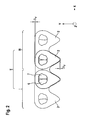
- Fig. 1 shows a section of a toothed link chain 1 according to the prior art in a side view in section. Shown are three adjacent chain links I, II and III, etc.
- X direction as chain longitudinal direction
- Y as height direction
- Z referred to as transverse direction.
- the height direction Y is referred to in the direction of the arrow Y as in the direction of the chain top and against the arrow direction as in the direction of the chain underside.
- the chain links I, II and III of the toothed link chain 1 comprise a plurality of link plates 2, which are each stacked apart from one another in the transverse direction Z of the link chain and thus form chain links.
- the link plates 2 adjacent chain links overlap in overlapping areas 3.
- each receiving openings 4 are arranged to protrude through the hinge pin 5.
- adjacent chain links are each hinged together.
- the hinge pins 5 each consist of two rocker jaws 6, 7, wherein each of the rocker pieces 6, 7 is respectively connected to the link plates 2 of one of the chain links and the rocker pieces 6, 7 roll on rolling surfaces 8, 9 on each other.
- the sprocket 7 is connected to the link plates of the chain link I
- the rocker 6 is connected to the link plates of the chain link II.
- the rocking contact point 10 of the two-dimensional representation of Fig. 1 is a point, this of course extends in the transverse direction Z along the cradles 6, 7 and thus forms a contact line in the three-dimensional representation.
- the link plates 2 each comprise two teeth 11, each having tooth flanks 12.
- the tooth flanks are each distinguished into an outer flank 12a and an inner flank 12b.
- guide tabs which can be arranged within the plate stack and serve to guide the toothed plate chain on a provided with a circumferential groove gear or cover plates, which are arranged at the transverse sides Z each outer sides of the toothed plate chain 1 and a guide effect in the axial direction of a gear by gripping the teeth of the gear.
- Fig. 1 is a well-known from the prior art measure to reduce the intake pulse at the inlet of the toothed link chain 1 is shown in a looped by this gear.
- the chain links I, II, III, etc. are formed from toothed plates whose teeth 11 have different outer contours of the tooth flanks 12.
- two different types of tabs are used, namely a first tab type B with an outer contour of the tooth flanks of type B and a second tab type S with an outer contour of the tooth flanks of type S.
- the two tab types B, S thus have a different outer contour , the differences in the outer contour exist only in the area of the tooth flanks.
- one of the tab types for example, a notch 13 as a distinguishing feature during assembly of the link chain 1.
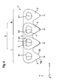
- Fig. 2 shows a tab chain according to the invention in a representation corresponding to Fig. 1 ,
- two types of tabs namely a first tab type B, which is identical to the first tab type B according to the embodiment of Fig. 1 is, and a second tab type A, which has a profile shift ⁇ of the tooth flanks 12 and the teeth 11, is used.
- a profile displacement ⁇ is understood as meaning a complete displacement of the profile and thus the outer contour of the teeth 11 in the vertical direction Y of the link chain 1.
- the profile displacement is effected in that, with the same outer contour of all link plates 2, the receiving openings 4 are arranged displaced in the second flap type A with respect to the receiving openings 4 of the first flap type.
- the inner contour of the receiving opening 4 is identical, the receiving opening 4 so in the two types of tabs only different within the link plate is arranged, or that the receiving openings 4 themselves have different inner contours.
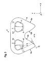
- Fig. 3 shows the outer contour K of an embodiment of a link plate, wherein the outer contour K is identical for both types of tabs as previously shown.
- the two types of latches differ by the position of the receiving openings, this is shown for the first flap type B with a dashed line 4.1 and for the second flap type A with a solid line 4.2.
- the position of the receiving openings 4.1 and 4.2 can be defined by the Wiege Industries. gleichtician 10 with elongated plate chain 1.
- the outer flank 12a is essentially a straight line section.
- the distance of the tooth flank 12 to the rocker contact point 10 is defined here by the distance of a perpendicular to the outer edge 12a passing through the rocking contact point 10 and a straight line 15 parallel to the perpendicular 14, which contacts the tooth flank 12.
- the first tab type B has a distance b of the tooth flank to the rocker contact point 10 which is smaller than the distance a of the tooth flank to the rocker contact point 10 of the second tab type A.
- the two tab types can therefore be made of the same semi-finished by a receiving opening 4 at different locations is introduced.
- a distinguishing feature such as a notch 13 or the like, may be attached to one of the two tab types.
- Fig. 2 shows a second embodiment of a tab chain according to the invention.
- the profile displacement is effected by different inner contours of the receiving openings 4.
- the receiving openings 4.2 of the second tab type A have an inner contour, which allow the hinge pin 5 a larger game. This can be effected, for example, by increasing the play of the rocker pieces of the adjacent chain links.
- Fig. 4 on the basis of three chain links I, II, III corresponding to the name in Fig. 1 explained.
- the link plates 2 of the chain link II have receiving openings 4.2, which are enlarged towards the chain top and thus allow the associated rocker 7 a larger game. As a result, the link plate 2 of the chain link II to the chain top, this is indicated by an arrow 16, moved.
- a flap chain 1 can chain links, each comprising only one type of lobe, be constructed. There is then chain links that include only the first strap type and chain links that include only the second strap type.
- the sequence of chain links is arbitrary, these can be arranged alternately or it can, for example, every second or every third or every fourth, etc. chain link consist of the one tab type, the other chain links can each consist of the other tab type. Likewise, it is possible to use the different types of mesh mixed within the chain links.
- a link plate of a chain link of the one strap type all other link plates of the other strap type.
Landscapes
- Engineering & Computer Science (AREA)
- General Engineering & Computer Science (AREA)
- Mechanical Engineering (AREA)
- Devices For Conveying Motion By Means Of Endless Flexible Members (AREA)
- Chain Conveyers (AREA)
- Load-Engaging Elements For Cranes (AREA)
Applications Claiming Priority (1)
| Application Number | Priority Date | Filing Date | Title |
|---|---|---|---|
| US90213807P | 2007-02-13 | 2007-02-13 |
Publications (2)
| Publication Number | Publication Date |
|---|---|
| EP1959160A2 true EP1959160A2 (fr) | 2008-08-20 |
| EP1959160A3 EP1959160A3 (fr) | 2009-05-06 |
Family
ID=39315012
Family Applications (1)
| Application Number | Title | Priority Date | Filing Date |
|---|---|---|---|
| EP08001021A Withdrawn EP1959160A3 (fr) | 2007-02-13 | 2008-01-21 | Chaîne à dents |
Country Status (3)
| Country | Link |
|---|---|
| US (1) | US8888634B2 (fr) |
| EP (1) | EP1959160A3 (fr) |
| DE (1) | DE102008005021A1 (fr) |
Families Citing this family (4)
| Publication number | Priority date | Publication date | Assignee | Title |
|---|---|---|---|---|
| US8474607B2 (en) * | 2010-11-19 | 2013-07-02 | Ramsey Products Corporation | Integrated multi-functional links for chain link conveyor and method |
| JP6314055B2 (ja) * | 2014-08-06 | 2018-04-18 | 株式会社椿本チエイン | サイレントチェーン |
| US10359097B2 (en) * | 2016-06-07 | 2019-07-23 | Hall Labs Llc | Silent chain profile for linear movement |
| USD809426S1 (en) * | 2016-09-14 | 2018-02-06 | Eric Gates | Link chain zipper |
Family Cites Families (33)
| Publication number | Priority date | Publication date | Assignee | Title |
|---|---|---|---|---|
| US757762A (en) * | 1901-09-26 | 1904-04-19 | Morse Chain Co | Drive-chain. |
| US799073A (en) * | 1901-12-24 | 1905-09-12 | Morse Chain Co | Drive-chain. |
| US1770989A (en) * | 1924-09-18 | 1930-07-22 | Morse Chain Co | Drive chain |
| US1755887A (en) * | 1927-12-23 | 1930-04-22 | Morse Chain Co | Power-transmission chain |
| US3742776A (en) * | 1971-10-20 | 1973-07-03 | Fmc Corp | Silent chain with improved rocker joint |
| US4010656A (en) * | 1974-02-07 | 1977-03-08 | Borg-Warner Corporation | Power transmission drive |
| US4130026A (en) * | 1976-11-18 | 1978-12-19 | Borg-Warner Corporation | Power transmission drive |
| JPS581304B2 (ja) * | 1979-04-09 | 1983-01-11 | トヨタ自動車株式会社 | チエ−ン伝動装置 |
| US4342560A (en) * | 1980-05-16 | 1982-08-03 | Borg-Warner Corporation | Composite chain link assembly |
| US4509323A (en) * | 1981-12-18 | 1985-04-09 | Borg-Warner Corporation | Power transmission chain |
| US4759740A (en) * | 1987-04-01 | 1988-07-26 | Borg-Warner Automotive, Inc. | Dual engaging silent chain drive |
| JPH0632515Y2 (ja) * | 1989-05-26 | 1994-08-24 | 株式会社椿本チエイン | 摩擦伝動用チェーン |
| JPH0484851U (fr) * | 1990-11-30 | 1992-07-23 | ||
| US5453059A (en) * | 1992-05-19 | 1995-09-26 | Borg-Warner Automotive, Inc. | Variable pitch silent chain |
| US5651746B1 (en) * | 1994-08-29 | 2000-01-04 | Borg Warner Automotive Kk | Power transmission chain |
| US5588926A (en) * | 1995-04-20 | 1996-12-31 | Borg-Warner Automotive, Inc. | Self-guided chain assemblies |
| US5758484A (en) * | 1996-09-30 | 1998-06-02 | Borg-Warner Automotive, Inc. | Silent chain with raised link backs |
| JP4059568B2 (ja) * | 1998-06-22 | 2008-03-12 | ボルグワーナー・モールステック・ジャパン株式会社 | サイレントチェーン |
| JP3096276B2 (ja) * | 1998-08-31 | 2000-10-10 | 株式会社椿本チエイン | サイレントチェーン伝動装置 |
| JP2000065156A (ja) * | 1998-08-21 | 2000-03-03 | Borg Warner Automotive Kk | サイレントチェーン伝動装置 |
| GB2348261B (en) * | 1998-12-24 | 2002-12-18 | Tsubakimoto Chain Co | Double-meshing-type silent chain drive and sprocket used therein |
| JP3076022B1 (ja) * | 1999-02-16 | 2000-08-14 | 株式会社椿本チエイン | サイレントチェーン伝動装置 |
| JP2000266131A (ja) * | 1999-03-16 | 2000-09-26 | Borg Warner Automotive Kk | サイレントチェーン |
| JP3054144B1 (ja) * | 1999-06-03 | 2000-06-19 | 株式会社椿本チエイン | サイレントチェーン |
| JP3384556B2 (ja) * | 2000-03-17 | 2003-03-10 | 株式会社椿本チエイン | 丸ピン型サイレントチェーン |
| JP3402591B2 (ja) * | 2000-09-26 | 2003-05-06 | 株式会社椿本チエイン | サイレントチェーン伝動機構 |
| JP2002250406A (ja) * | 2001-02-23 | 2002-09-06 | Tsubakimoto Chain Co | ランダム配置型サイレントチェーン |
| JP2003065398A (ja) * | 2001-08-23 | 2003-03-05 | Borg Warner Morse Tec Japan Kk | サイレントチェーン用リンクプレート、該リンクプレートを含むサイレントチェーンおよび該サイレントチェーンを含むサイレントチェーン伝動装置 |
| JP3589650B2 (ja) * | 2001-12-20 | 2004-11-17 | 株式会社椿本チエイン | サイレントチェーン伝動機構 |
| US20050049098A1 (en) * | 2003-08-28 | 2005-03-03 | Borgwarner Inc. | High-performance silent chain |
| US7850565B2 (en) * | 2005-06-14 | 2010-12-14 | Luk Lamellen Und Kupplungsbau Beteiligungs Kg | Plate-link chain |
| US20070105676A1 (en) * | 2005-10-26 | 2007-05-10 | Luk Lamellen Und Kupplungsbau Beteiligungs Kg | Link plate for a plate-link chain |
| US7803080B2 (en) * | 2005-12-13 | 2010-09-28 | Borgwarner Inc. | High strength and stiffness silent chain with improved noise |
-
2008
- 2008-01-21 DE DE102008005021A patent/DE102008005021A1/de not_active Ceased
- 2008-01-21 EP EP08001021A patent/EP1959160A3/fr not_active Withdrawn
- 2008-02-13 US US12/069,909 patent/US8888634B2/en active Active
Non-Patent Citations (1)
| Title |
|---|
| None |
Also Published As
| Publication number | Publication date |
|---|---|
| US20090192000A1 (en) | 2009-07-30 |
| EP1959160A3 (fr) | 2009-05-06 |
| DE102008005021A1 (de) | 2008-08-14 |
| US8888634B2 (en) | 2014-11-18 |
Similar Documents
| Publication | Publication Date | Title |
|---|---|---|
| DE69023021T2 (de) | Kraftübertragungskette. | |
| DE102004007100B4 (de) | Laschen für eine Mehrzahl unterschiedlicher Laschenketten für Kegelscheibenumschlingungsgetriebe sowie Laschenkette | |
| DE19922827B4 (de) | Umschlingungsmittel | |
| DE19809963B4 (de) | Beidseitig eingreifende Zahnkette | |
| DE102008024355B4 (de) | Geräuscharmer Kettentrieb | |
| DE4234839A1 (de) | Rollenkette mit regelloser teilung | |
| DE19809853A1 (de) | Beidseitig eingreifende Zahnkette | |
| DE3116834A1 (de) | Zusammengesetzte kettengliedereinheit | |
| DE102012215204B4 (de) | Zahnkette | |
| DE10006818A1 (de) | Zahnketten-Vorrichtung | |
| DE102009008802A1 (de) | Zahnrad für eine Kette | |
| DE102009017455A1 (de) | Zahnrad für eine Kette | |
| EP1855026A2 (fr) | Chaîne à plaquettes | |
| WO2017032372A1 (fr) | Chaîne articulée suivant un assemblage à trois plaquettes | |
| DE102005027328B4 (de) | Zweiseitige Zahnkette | |
| DE69911873T2 (de) | Zahnkette mit Scherbolzenlöcher aufweisenden Laschen und mit Vanadiumcarbid beschichteten Bolzen | |
| DE19929823B4 (de) | Geräuscharme Kette | |
| EP1959160A2 (fr) | Chaîne à dents | |
| DE102008047371A1 (de) | Geräuscharme Kette | |
| DE19529146A1 (de) | Kraftübertragende Zahnkette | |
| DE102017107790A1 (de) | Zahnräder mit variierendem Eingriffswinkel | |
| DE102010019091A1 (de) | Zahnkette | |
| EP2366917B1 (fr) | Chaîne dentaire dotée de chaînes articulées optimisées | |
| EP1458993A1 (fr) | Transmission a courroie destinee notamment a la transmission d'une force entre deux paires de disques coniques de la transmission | |
| DE3844243A1 (de) | Endloser transmissionsriemen |
Legal Events
| Date | Code | Title | Description |
|---|---|---|---|
| PUAI | Public reference made under article 153(3) epc to a published international application that has entered the european phase |
Free format text: ORIGINAL CODE: 0009012 |
|
| AK | Designated contracting states |
Kind code of ref document: A2 Designated state(s): AT BE BG CH CY CZ DE DK EE ES FI FR GB GR HR HU IE IS IT LI LT LU LV MC MT NL NO PL PT RO SE SI SK TR |
|
| AX | Request for extension of the european patent |
Extension state: AL BA MK RS |
|
| PUAL | Search report despatched |
Free format text: ORIGINAL CODE: 0009013 |
|
| AK | Designated contracting states |
Kind code of ref document: A3 Designated state(s): AT BE BG CH CY CZ DE DK EE ES FI FR GB GR HR HU IE IS IT LI LT LU LV MC MT NL NO PL PT RO SE SI SK TR |
|
| AX | Request for extension of the european patent |
Extension state: AL BA MK RS |
|
| AKX | Designation fees paid | ||
| STAA | Information on the status of an ep patent application or granted ep patent |
Free format text: STATUS: THE APPLICATION IS DEEMED TO BE WITHDRAWN |
|
| 18D | Application deemed to be withdrawn |
Effective date: 20091107 |
|
| REG | Reference to a national code |
Ref country code: DE Ref legal event code: 8566 Ref country code: DE Ref legal event code: R108 Effective date: 20100406 |
|
| P01 | Opt-out of the competence of the unified patent court (upc) registered |
Effective date: 20230522 |