EP1960177B1 - Spritzgiesscoform- und montageverfahren und -vorrichtung für aus kunststoffmaterial hergestellte artikel mit durch anlenken während eines entformungsschritts verbindbaren teilen - Google Patents
Spritzgiesscoform- und montageverfahren und -vorrichtung für aus kunststoffmaterial hergestellte artikel mit durch anlenken während eines entformungsschritts verbindbaren teilen Download PDFInfo
- Publication number
- EP1960177B1 EP1960177B1 EP06818347A EP06818347A EP1960177B1 EP 1960177 B1 EP1960177 B1 EP 1960177B1 EP 06818347 A EP06818347 A EP 06818347A EP 06818347 A EP06818347 A EP 06818347A EP 1960177 B1 EP1960177 B1 EP 1960177B1
- Authority
- EP
- European Patent Office
- Prior art keywords
- molding
- pin
- hinge pin
- annular element
- demolding
- Prior art date
- Legal status (The legal status is an assumption and is not a legal conclusion. Google has not performed a legal analysis and makes no representation as to the accuracy of the status listed.)
- Active
Links
Images





Classifications
-
- B—PERFORMING OPERATIONS; TRANSPORTING
- B65—CONVEYING; PACKING; STORING; HANDLING THIN OR FILAMENTARY MATERIAL
- B65D—CONTAINERS FOR STORAGE OR TRANSPORT OF ARTICLES OR MATERIALS, e.g. BAGS, BARRELS, BOTTLES, BOXES, CANS, CARTONS, CRATES, DRUMS, JARS, TANKS, HOPPERS, FORWARDING CONTAINERS; ACCESSORIES, CLOSURES, OR FITTINGS THEREFOR; PACKAGING ELEMENTS; PACKAGES
- B65D25/00—Details of other kinds or types of rigid or semi-rigid containers
- B65D25/28—Handles
- B65D25/32—Bail handles, i.e. pivoted rigid handles of generally semi-circular shape with pivot points on two opposed sides or wall parts of the conainter
-
- B—PERFORMING OPERATIONS; TRANSPORTING
- B29—WORKING OF PLASTICS; WORKING OF SUBSTANCES IN A PLASTIC STATE IN GENERAL
- B29C—SHAPING OR JOINING OF PLASTICS; SHAPING OF MATERIAL IN A PLASTIC STATE, NOT OTHERWISE PROVIDED FOR; AFTER-TREATMENT OF THE SHAPED PRODUCTS, e.g. REPAIRING
- B29C45/00—Injection moulding, i.e. forcing the required volume of moulding material through a nozzle into a closed mould; Apparatus therefor
- B29C45/0017—Injection moulding, i.e. forcing the required volume of moulding material through a nozzle into a closed mould; Apparatus therefor moulding interconnected elements which are movable with respect to one another, e.g. chains or hinges
-
- B—PERFORMING OPERATIONS; TRANSPORTING
- B29—WORKING OF PLASTICS; WORKING OF SUBSTANCES IN A PLASTIC STATE IN GENERAL
- B29C—SHAPING OR JOINING OF PLASTICS; SHAPING OF MATERIAL IN A PLASTIC STATE, NOT OTHERWISE PROVIDED FOR; AFTER-TREATMENT OF THE SHAPED PRODUCTS, e.g. REPAIRING
- B29C45/00—Injection moulding, i.e. forcing the required volume of moulding material through a nozzle into a closed mould; Apparatus therefor
- B29C45/0053—Injection moulding, i.e. forcing the required volume of moulding material through a nozzle into a closed mould; Apparatus therefor combined with a final operation, e.g. shaping
- B29C45/006—Joining parts moulded in separate cavities
-
- B—PERFORMING OPERATIONS; TRANSPORTING
- B29—WORKING OF PLASTICS; WORKING OF SUBSTANCES IN A PLASTIC STATE IN GENERAL
- B29C—SHAPING OR JOINING OF PLASTICS; SHAPING OF MATERIAL IN A PLASTIC STATE, NOT OTHERWISE PROVIDED FOR; AFTER-TREATMENT OF THE SHAPED PRODUCTS, e.g. REPAIRING
- B29C45/00—Injection moulding, i.e. forcing the required volume of moulding material through a nozzle into a closed mould; Apparatus therefor
- B29C45/0017—Injection moulding, i.e. forcing the required volume of moulding material through a nozzle into a closed mould; Apparatus therefor moulding interconnected elements which are movable with respect to one another, e.g. chains or hinges
- B29C2045/0018—Injection moulding, i.e. forcing the required volume of moulding material through a nozzle into a closed mould; Apparatus therefor moulding interconnected elements which are movable with respect to one another, e.g. chains or hinges moulding containers with handle, e.g. buckets
-
- B—PERFORMING OPERATIONS; TRANSPORTING
- B29—WORKING OF PLASTICS; WORKING OF SUBSTANCES IN A PLASTIC STATE IN GENERAL
- B29C—SHAPING OR JOINING OF PLASTICS; SHAPING OF MATERIAL IN A PLASTIC STATE, NOT OTHERWISE PROVIDED FOR; AFTER-TREATMENT OF THE SHAPED PRODUCTS, e.g. REPAIRING
- B29C45/00—Injection moulding, i.e. forcing the required volume of moulding material through a nozzle into a closed mould; Apparatus therefor
- B29C45/0053—Injection moulding, i.e. forcing the required volume of moulding material through a nozzle into a closed mould; Apparatus therefor combined with a final operation, e.g. shaping
- B29C45/006—Joining parts moulded in separate cavities
- B29C2045/007—Joining parts moulded in separate cavities assembling a container and a handle
-
- B—PERFORMING OPERATIONS; TRANSPORTING
- B29—WORKING OF PLASTICS; WORKING OF SUBSTANCES IN A PLASTIC STATE IN GENERAL
- B29L—INDEXING SCHEME ASSOCIATED WITH SUBCLASS B29C, RELATING TO PARTICULAR ARTICLES
- B29L2031/00—Other particular articles
- B29L2031/712—Containers; Packaging elements or accessories, Packages
-
- Y—GENERAL TAGGING OF NEW TECHNOLOGICAL DEVELOPMENTS; GENERAL TAGGING OF CROSS-SECTIONAL TECHNOLOGIES SPANNING OVER SEVERAL SECTIONS OF THE IPC; TECHNICAL SUBJECTS COVERED BY FORMER USPC CROSS-REFERENCE ART COLLECTIONS [XRACs] AND DIGESTS
- Y10—TECHNICAL SUBJECTS COVERED BY FORMER USPC
- Y10T—TECHNICAL SUBJECTS COVERED BY FORMER US CLASSIFICATION
- Y10T428/00—Stock material or miscellaneous articles
- Y10T428/13—Hollow or container type article [e.g., tube, vase, etc.]
- Y10T428/1352—Polymer or resin containing [i.e., natural or synthetic]
Definitions
- This invention refers to the manufacturing of articles made of plastic material comprising separate parts, which are assemblable and connectable by hinging during the demolding step from a mold.
- the invention concerns a method and an apparatus for the injection co-moiding of articles made of plastic material, the articles comprising separate parts respectively provided with a hinge pin and with an annular element, which can be automatically connected by hinging during a demolding step of the molded article from a mold, after the opening of the same mold.
- thermoplastic material articles made by injection molding processes in particular of articles composed of several parts which have to be assembled and connected to one another by hinging, for example in the manufacturing of containers provided with a support handle
- methods and apparatuses capable of enabling a co-molding of the various parts and their automatic assembling directly inside the mold.
- IT 1.260.680 describes a press for the co-molding of containers provided with a handle, in which use is made of a demolding system, separate from the controls for opening the press, and in which the steps of opening the mold and of assembling the handle onto the container are carried out at separate stages, before the final demolding step the molded article.
- EP 0 912 411 in turn shows an articulated connection between two parts of an article made of plastic material, the articulated connection comprising a hinge pin and an annular element which are molded simultaneously, in such a way as to come out joined together by means of suitable lacerable gates; subsequently, upon an at least partial removal of the article from the injection mold, the two parts of the articulated connection are then assembled together by breaking the same gates.
- US 6.234.782 illustrates an injection mold for manufacturing of a container provided with a handle, in which the handle is automatically assembled onto the container by means of an additional assembling device operated by a respective control cylinder, separate from the demolding device.
- WO 93/13927 A relates to in-mold formation and assembly of actuator-overcap and insert nozzle;
- the molding mechanism comprises mold components, and an assembly made up of riser plate and slide, which is a component of the means for repositioning and inserting the spray nozzle insert into the actuator-overcap, the mechanism further comprising a movable insert engaging pin within the slide for partly forming the mold for spray nozzle insert.
- mold components separate, and slide moves backward relative to riser plate by a diagonal cam pin, pulling spray nozzle insert out of its molded position; a cam bar is then moved relative to a cam roller connected to a mold component to force riser plate away from the same mold component in order to position insert engaging pin in line with actuator-overcap structure.
- a cam follower connected to insert engaging pin is moved by the cam bar for assembling the insert with the actuator-overcap structure, the slide being prevented from moving; finally, the assembled actuator-overcap with the insert is now ejected by conventional mold ejection technology.
- the main object of this invention is to provide a method and an apparatus for injection co-molding of articles made of plastic material, the articles comprising parts hinged to one another, whereby it is possible to reduce the working cycle times, and carry out an automatic assembling of the parts directly in the mold, during the demolding step of the molded article.
- a further object of the invention is to provide an apparatus, as mentioned above, suitable for use in a conventional injection molding press, whereby it is possible to exploit the linear movements of certain members of the same press to achieve the assembling of the parts, by means of a simple solution which does not require the use of additional devices and control systems.
- Another further object of the invention is to provide a method and an apparatus, as mentioned above, whereby it is possible to produce molded articles having thin thicknesses and/or having plane walls, without running the risk that the deformation of the parts due to their limited thickness and/or their geometry is such as to prevent the assembling operation of the same parts.
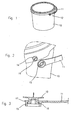
- reference number 10 has been used to indicate a generic molded container of plastic material, provided with a supporting handle 11, co-molded with the container 10, which are designed to be assembled directly in the mold and hinged in diametrically opposite positions; by means of a joint indicated as a whole by reference number 12, only one of which is visible in figure 1 .
- the joint comprises a hinge pin 14 radially protruding from the container 10, and an annular element 15 at one end of the handle 11, the annular element 15 providing an extensive supporting surface for the pin 14, onto which is discharged the entire weight of the completely filled container, as explained further on.
- the hinge pin 14 and the annular element 15 may be shaped in any way, provided that they are suitable for snap-on coupling by means of an axial thrust, by exploiting the elastic yielding of the plastic material.
- the cylindrical pin 14 has a slightly conical-shaped head 16, designed to be snap forced into the hole in the ring 15 to prevent it from slipping out, while at the same time allowing the rotation of the handle 11.
- the apparatus comprises an injection mold suitable for co-molding the container 10 and the handle 11 in separate impressions, by means of the same plastic material or by means of different plastic materials.
- the mold comprises a first mold part 20 and a second mold part 21, designed to be secured to the plates of a conventional injection press which, in their closed condition, define the molding impressions for molding the container 10 and the handle 11, into which is injected a thermoplastic material in the melted state, in a per se known way, for example through an injection hole 22 in the mold part 21.
- the impressions for the container 10 and for the handle can either be completely separate from each other or joined by one or more channels for the passage of the flow of melted plastic material, to facilitate the filling of the aforesaid impressions.
- reference number 23 has been used to indicate the assembly of a demolding device for the molded article, forming an integral part of the mold, the linear movements of which are advantageously used for assembling the handle 11 on the container 10 during the initial moments of the demolding step for the molded article, in accordance with this invention, as described further on.
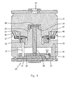
- the mold part 20 comprises a central core 24 designed to penetrate into a corresponding cavity in the mold part 21, to form a first impression 25 of the container 10, as well as a second mold impression of the handle 11, not shown.
- the mold part 20 also comprises a demolding ring 26 disposed coaxially to the central core 24.
- Two auxiliary molding assemblies 27, which cooperate to form the impression of the hinge pin 14 and of the ring 15 of the handle with respective cam control systems, are associated with the mold part 20 to move with the demolding ring 26.
- the demolding device 23 comprises a central thrust member, having a mushroom-shaped head 28 in contact with the bottom wall of the container 10, from which extends rearwardly a shank 29 secured to a first plate 30; the plate 30 is subject to the action of thrust rods 32, actuated by linear movements of the injection press, only one of which is shown in figure 5 .
- a second plate 31 is interposed between the first thrust plate 30 and a third plate 33 secured to the mold part 20 by means of stay bolts 34, only one of which is shown in figure 4 .
- the plates 30 and 31 are connected to each other by a disengageable coupling device 35, so as to be moved conjointly or separately by the thrust rods 32, as explained further on, guided in their movement by columns 36, one of which is shown in figure 5 .
- the intermediate plate 31 is also provided with thrust columns 37, figure 4 , to move the demolding ring 26 in the direction of the axis of the mold.
- reference number 38 in figure 5 has been used to indicate a demolding rod for demolding of the handle, connected to the plate 30.
- each assembly 27 comprises two coaxially arranged molding members which cooperate to form the impressions for the pin 14 of the container and for the ring 15 of the supporting handle 11.
- each auxiliary molding assembly 27 comprises a first solid pin 40, shaped so as to define both the internal impression of the hinge pin 14, and the internal impression for the ring 15.
- the assembly 27 also comprises a second tubular pin 41, coaxially sliding on the internal pin 40.
- Both the pin 40 and the pin 41 end with a head 42, 43 provided with a cross stud 44, 45 sliding along the groove of a respective control cam 46, 47 suitably shaped to selectively control, in an independent and co-ordinate way, the forward and backward movements of the two pins 40, 41, during the movement of the ring 26 at the beginning of the demolding step for the molded container.
- the operative method of the mold is based on the steps referred to hereunder, illustrated in figures from 6 to 13.
- the opening of the press and the partial or total movement of the mold part 21 away from the mold part 20, is followed by the demolding step for the molded article.
- the rods 32 exploiting the linear movements of the press, push forward the first demolding plate 30 together with the intermediate plate 31 to which it is mechanically connected by means of the coupling devices 35.
- the forward movement of the plates 30 and 31, causes the simultaneous forward movement of the central thrust member 28, 29, of the demolding ring 26 and of the demolding rod 38 of the handle. In this way the container 10 and the handle 11 begin to detach from their respective impressions.
- This movement in the direction of the axis of the mold, in particular of the demolding ring 26, is accompanied by a coordinated movement of the molding pins 40, 41 which, following the two cams 46, 47, shift radially, performing such coordinated movements as to cause the coupling of the ring 15 to the hinge pin 14 in an aligned condition, by means of an axial thrust and a subsequent disengagement of the same pins to complete the demolding of the container and of the handle in an already assembled condition.
- Figure 4 shows the initial position of the demolding ring 26 and of the two pins 40 and 41, at the end of the molding step.
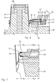
- the initial position of the pins 40 and 41 is also indicated, by a broken line, in figure 6 and in the enlarged detail of figure 7 .
- the two pins 40 and 41 cooperate with internal surfaces of the mold, to form the molding impressions of the hinge pin 14 and of the ring 15 of the supporting handle.
- Figures 6 and 7 also show, by a continuous line, a second position of the ring 26 with the central mushroom shaped head 28 for demolding of the container 10 and of the pins 40, 41, following a slight forward movement of the two plates 30 and 31.
- the radial movements of the pins 40 and 41 are controlled and coordinated by the respective cams 46 and 47; in the condition of figures 6 and 7 , following the first forward movement of the ring 26, the internal pin 40 is shifted slightly backwards with respect to the hinge pin 14, while the tubular pin 41 is made to move forward pushing the ring 15 of the handle against the conical head 16 of the hinge pin; simultaneously, the container 10 also begins to be partially expelled from the mold part 20.
- Figures 8 and 9 show a second condition during the step of demolding and assembling of the handle and the container, following a further shifting forward of the plates 30 and 31.
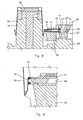
- Figures 10 and 11 show a third intermediate condition, in which the internal pin 40 has been shifted away even further, while the external pin 41 remains in its forward position.
- Figures 12 and 13 show a final condition, during the course of the demolding step, in which both the pins 40 and 41 have been shifted completely back, freeing both the hinge pin 14 and the ring 15 of the supporting handle.
- the devices 35 are operated to free the plate 30 from the plate 31; continuing the movement of the rods 32, the container 10 with the handle 11 perfectly assembled, can be finally disengaged from the demolding ring 26, and expelled from the mold.
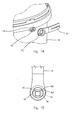
- figures 14 and 15 show a second possible solution for the hinge pin 14 and for the ring 15.
- the pin 14 is again cylindrically shaped, having a radius R1 smaller than the internal radius R2 of the ring 15.
- the head 16 of the hinge pin is has a substantially oval shape, the major axis of which extends in a horizontal, or transversal direction to the axis of the container 10.
- the head 16 of the hinge pin in the direction of its minor axis, in turn has a curvature radius R3 identical to the internal curvature radius R1 of the ring 15; the same ring 15, on the rear side facing towards the container, has an oval hole which adapts to the shape of the head 16, to allow the snap-on assembling, by means of a simple axial thrust of the molding pin 41, as mentioned previously.
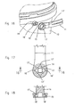
- Figures 16, 17 and 18 show a third solution for a hinge joint that can be assembled during the demolding step of the molded article, in accordance with the method of this invention.
- the pin 14 is provided with two radial teeth 16' disposed horizontally with respect to the container 10, while the ring 15, in correspondence with the rear shoulder 17 is provided with two slits 17', aligned with the teeth 16' in the assembling condition inside the mold, shown in figure 16 .
- the coupling parts of the pins 14 and of the rings 15 must be made in such a way as to offer a slight interference in order to allow a reciprocal snap-on engagement, by means of the elastic yielding of the plastic material, preventing their subsequent disengagement, whatever position is assumed by the handle 11 with respect to the container 10.
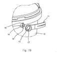
- Figure 19 shows a fourth solution wholly similar to that of the previous example, the only difference being that now the teeth 16' have a vertical disposition; therefore, in figure 19 the same reference numbers have been used to indicate similar or equivalent parts.
- Figure 20 shows another solution for the hinge joint, which can be realised by a method and an apparatus according to a second embodiment of the present invention, as illustrated in Figures 21 to 26 , in which the same reference numbers have been used to indicate similar or equivalent parts to those of the previous embodiment.
- reference number 10 has been used again to indicate a generic container molded from plastic material, provided with a supporting handle 11, co-molded with the container 10, designed to be assembled directly in the mold and hinged in diametrically opposite positions by means of a joint indicated as a whole by reference number 12.
- the joint comprises again a hinge pin 14 radially protruding from the container 10, and an annular element 15 at one end of the handle 11.
- the hinge pin 14 and the annular element 15 may be shaped in any way, provided that they are suitable for quick coupling by means of an axial thrust, by exploiting the elastic yielding of the plastic material.
- the pin 14 illustrated is cylindrically shaped and has a head 16, designed to be snap forced into the hole in the annular element 15 to prevent it from slipping out, while at the same time allowing the rotation of the handle 11.
- the annular element 15 has an internal shoulder 15' designed to prevent the same annular element 15 from slipping off the pin 14 once they have been assembled together, by interference with the head 16.
- the internal shoulder 15' has a conical lead-in surface 15" for coupling the annular element 15 onto the hinge pin 14; alternatively, the lead-in surface can be provided on the head 16 of the pin 14.
- the apparatus comprises an injection mold suitable for co-molding the container 10 and the handle 11 in separate impressions, by means of the same plastic material or by means of plastic materials differing from each other.
- the mold comprises again a first mold part 20 and a second mold part 21, designed to be secured to the plates of a conventional injection press which, in their closed condition, define the impressions for molding the container 10 and the handle 11, into which is injected a thermoplastic material in the melted state, in a per se known way, for example through an injection hole 22 in the mold part 21.
- the mold part 20 comprises a central core 24 designed to penetrate into a corresponding cavity in the mold part 21, to form a first impression 25 of the container 10, as well as a second mold impression of the handle 11, not shown.
- the mold part 20 also comprises a demolding ring 26 disposed coaxially to the central core 24.
- Two auxiliary molding assemblies 27, which cooperate to form the impressions of the hinge pin 14 and of the ring 15 of the handle with respective cam control systems, are associated with the mold part 20 to move together with the demolding ring 26.
- a demolding device 23 comprises a central thrust member, having a mushroom shaped head 28 in contact with the bottom wall of the container 10, from which rearwardly extends a shank 29 secured to a first plate 30; the plate 30 is subject to the action of thrust rods, not shown, controlled by linear movements of the injection press.
- a second plate 31 is interposed between the first thrust plate 30 and a third plate 33 secured to the mold part 20 by means of tie rods 34, only one of which is shown in figure 26 .
- the plates 30 and 31 are connected to each other by a disengageable coupling device 35, so as to be moved conjointly or separately by the thrust rods, as explained further on.
- the intermediate plate 31 is also provided with thrust columns 37, to move the demolding ring 26 in the direction of the axis of the mold.
- a demolding rod is provided for demolding of the handle, connected to the plate 30.
- each assembly 27 comprises two coaxial molding members which cooperate to form the impressions for the pin 14 of the container and of the ring 15 of the supporting handle 11.
- each auxiliary molding assembly 27 comprises a first solid pin 40, shaped in such a way as to define at the same time the internal impression of the hinge pin 14 by one of its ends 40', as well as the internal impression for the annular element 15 with part of the body of the same pin 40.
- the pin 40 comprises on its body a continuous or discontinuous peripheral groove 40", defining the molding impression for the internal shoulder 15' of the annular hinging element 15; the peripheral groove 40" is provided on one axial end with a conical surface 40"' shaped and disposed to form on the internal shoulder 15' the conical lead-in surface 15" for coupling the annular element 15 onto the hinge pin 14.
- the assembly 27 also comprises a second tubular pin 41, sliding coaxially on the internal pin 40.
- Both the pin 40 and the pin 41 end with a head 42, 43 provided with a cross stud 44, 45 sliding along the groove of a respective control cam 46, 47 suitably shaped to selectively control, in an independent and co-ordinate way, the forward and backward movements of the two pins 40, 41, during the movement of the ring 26 at the beginning of the demolding step for the molded container.
- the pin 40 of the first molding member comprises disengageable means for axially retaining the hinge pin 14 during the coupling of the pin 14 itself with the annular element 15.
- the axial retaining means comprise continuous or discontinuous peripheral toothing 50 on the pin 40 of the first molding member, designed to engage with the hinge pin 14, during the injection molding of the pin 14 itself.
- the operative method of the mold is based on the steps set forth hereunder, with reference to the figures from 21 to 26.
- a step is started of opening the mold and demolding the finished article.
- the opening of the press and the partial or total movement of the mold part 21 away from the mold part 20, is followed by the demolding step of the molded article.
- This movement in the direction of the axis of the mold, in particular of the demolding ring 26, is accompanied by a coordinated movement of the molding pins 40, 41 which, following the two cams 46, 47, shift radially, performing a coordinated movement such as to cause the coupling of the annular element 15 with the hinge pin 14 in an aligned condition, by means of an axial thrust and a subsequent disengagement of the same pins to complete the demolding of the container and the handle in an already assembled condition.
- Figure 21 shows the initial position of the two pins 40 and 41, at the end of the molding step.
- the two pins 40 and 41 cooperate with internal surfaces of the mold, to form the molding impressions of the hinge pin 14 and of the ring 15, with the relevant shoulder 15, of the supporting handle.
- the peripheral toothing 50 on the pin 40 of the first molding member engages with the pin 14, in that the pin 14 is overmolded on the end 40' of the same pin 40, thereby enabling the toothing 50 to exert its retaining action once the material has acquired the necessary resistance, after a first cooling step.
- the radial movements of the pins 40 and 41 are controlled and coordinated by the respective cams 46 and 47; in the condition of figure 22 , following the first forward movement of the ring 26, the tubular pin 41 is made to move forward pushing the annular element 15 of the handle, towards the head 16 of the hinge pin.
- Figure 23 shows a second condition during the step of demolding and assembling of the handle and the container; in this condition, the pin 41 has again been made to move forward, forcing the ring 15 of the handle to engage by snapping onto the hinge pin 14; during this initial phase of the demolding step, the handle 11 and the container 10 are therefore assembled directly in the mold, during the course of the same demolding.
- the toothing 50 of the pin 40 exerts an axial retaining action on the pin 14 itself; in this way, only a minimal part of the axial force exerted by the annular element 15 on the pin 14 is transferred and discharged onto the container 10, thanks to the axial retaining action exerted on the pin 14 itself.
- Figure 24 shows a third intermediate condition, in which the internal pin 40 has remained in its forward position, while the external pin 41 has been made to move backwards, so as to release the head 16 of the pin 14 and thereby enable the pin 14 itself to dilate freely during the subsequent disengagement step of the toothing 50 of the pin 40.
- figure 25 shows the final condition, during the course of the demolding step, in which the pin 40 has also been made to move backwards, causing the disengagement of the retaining toothing 50 from the hinge pin 14, which is facilitated by the presence of an appropriate conical surface or fillet 51 provided on a rear side of the toothing 50, as illustrated in figure 25 .
- the container 10 with the handle 11 perfectly assembled can be finally disengaged from the demolding ring 26, and expelled from the mold.
- the apparatus according to this embodiment of the invention thanks to the retaining means of the hinge pin 14, and thanks to the fact that the dilation of the annular hinge element 15 occurs directly on the pin 40, makes it possible to reduce to a minimum the stresses transmitted by the pin 14 to the container 10 during the assembling of the handle 11.
Landscapes
- Engineering & Computer Science (AREA)
- Mechanical Engineering (AREA)
- Manufacturing & Machinery (AREA)
- Moulds For Moulding Plastics Or The Like (AREA)
- Injection Moulding Of Plastics Or The Like (AREA)
Claims (15)
- Verfahren zum gemeinsamen Spritzgießen und zum Montieren für einen Artikel, der aus einem Kunststoffmaterial hergestellt ist, wobei der Artikel ein mit einem Zapfen (14) versehenes erstes Formteil (10) und ein mit einem ringförmigen Element (15) versehenes zweites Formteil (11) aufweist, die ausgestaltet sind, um unmittelbar in dem Spritzgießwerkzeug (20, 21) gelenkig miteinander verbunden zu werden,- wobei das ringförmige Element (15) und der Zapfen (14) gemeinsam spritzgegossen und anschließend durch Schnappen miteinander gekoppelt werden und der Artikel durch eine Entformungsvorrichtung (23) entformt wird,wobei das Verfahren die folgenden Schritte aufweist:- Versehen des Formwerkzeugs (20, 21) mit einer ersten Formkomponente (40), die eine Vertiefung für den Zapfen (14) bildet und jeweils mit einer zweiten Formkomponente (41), die eine Vertiefung für das ringförmige Element (15) bildet, wobei die erste und die zweite Formkomponente (40, 41) in Bezug aufeinander axial bewegbar sind, und- Versehen des Formwerkzeugs (20, 21) mit einer Kurvensteuerungseinrichtung (46, 47), die angepasst ist, um die erste und zweite Formkomponente (40, 41) gezielt zu bewegen, um die Formteile zu montieren, indem ein Schnappeingriff des ringförmigen Elements (15) mit dem Zapfen (14) bewirkt wird, gekennzeichnet durch die folgenden zusätzlichen Schritte:- Vorsehen der ersten und der zweiten Formkomponente (40, 41) an einem beweglichen Teil (26) der Entformungsvorrichtung (23),- gemeinsames Gießen des ringförmigen Elements (15) und des Zapfens (14) in einem Zustand in axialer Ausrichtung,- Koppeln des ringförmigen Elements (15) und des Zapfens (14) durch axiales Bewegen von zumindest einer der ersten und zweiten Formkomponente (40, 41) durch das bewegliche Teil (26) der Entformungsvorrichtung (23) und die Kurveneinrichtung (46, 47) während einer anfänglichen Phase der Entformung des Artikels von dem Formwerkzeug und- Lösen der Formkomponenten (40, 41) von dem ringförmigen Element (15) und von dem Zapfen (14) und anschließend Vervollständigen der Entformung des Artikels mit dem ersten und zweiten Formteil (10, 11) in ihrem montierten Zustand.
- Verfahren nach Anspruch 1, gekennzeichnet durch das Bewirken einer Abfolge koordinierter Bewegungen der Formkomponenten (40, 41), die ihrer Bewegung in Bezug auf die Kurvensteuerungseinrichtung (46, 47) in derselben Richtung des Entformens folgen.
- Verfahren nach Anspruch 2, das durch eine Spritzgießpresse ausgeführt werden soll, die eine Entformungsvorrichtung (23) für die geformten Artikel aufweist, die in einer axialen Richtung linear bewegbar ist, gekennzeichnet durch das Bewirken der koordinierten Abfolge von Bewegungen der Formkomponenten (40, 41) in Bezug auf eine lineare Bewegung der Entformungsvorrichtung (23).
- Verfahren nach Anspruch 1, dadurch gekennzeichnet, dass die Abfolge von Bewegungen der Formkomponenten (40, 41) gleichzeitig oder bei nachfolgenden Bewegungen aufweist:eine erste Bewegung nach hinten für eine erste Formkomponente (40), um sie mit dem Zapfen (14) außer Eingriff zu bringen,eine zweite Bewegung nach vorne der zweiten Formkomponente (41), um einen axialen Druck auszuüben, der geeignet ist,um das ringförmige Element (15) mit dem Zapfen (14) in Eingriff zu bringen, undeine nachfolgende abschließende Bewegung, um die zuvor erwähnten Formkomponenten (40, 41) von dem ringförmigen Element (15) und von dem Zapfen (14) weg zu bewegen.
- Verfahren nach Anspruch 1, gekennzeichnet durch den zusätzlichen Schritt:- Ausüben einer axialen Haltewirkung auf den Zapfen (14) mit Hilfe der ersten Formkomponente (40) während des Koppelns des ringförmigen Elements (15) mit dem Zapfen (14) des Artikels.
- Verfahren nach Anspruch 5, gekennzeichnet durch Versehen der ersten Formkomponente (40) mit außer Eingriff bringbaren Mitteln (50) zum axialen Halten des Zapfens (14) und
durch Ineingriffbringen des Zapfens (14) mit der ersten Komponente (40) während des Spritzgießens. - Vorrichtung zum gemeinsamen Spritzgießen und Montieren für einen Artikel, der aus Kunststoffmaterial hergestellt ist,
wobei der Artikel ein mit einem Zapfen (14) versehenes erstes Formteil (10) und ein mit einem ringförmigen Element (15) versehenes zweites Formteil (11) aufweist, die durch drehbare Befestigung verbindbar sind, wobei die Vorrichtung aufweist:ein Spritzgießwerkzeug (20, 21), das Gießvertiefungen für das erste und das zweite Formteil (10, 11) eines aus Kunststoffmaterial hergestellten Artikels bildet,eine Entformungsvorrichtung (23), die linear in einer axialen Richtung des Formwerkzeugs bewegbar ist,eine erste und eine zweite Formkomponente (40, 41), die Gießvertiefungen des ringförmigen Elements (15) und des Zapfens (14) bilden, wobei die Formkomponenten (40, 41) in Bezug aufeinander bewegbar sind, undeine Kurvensteuerungseinrichtung (46, 47) zum gezielten Bewegen der Formkomponenten (40, 41) zwischen einem Vorwärtsformzustand, einem Montagezustand und einem Rückwärtszustand zum Außereingriffbringen des Zapfens (14) unddes ringförmigen Gelenkelements (15),dadurch gekennzeichnet, dass die Formkomponenten (40, 41) durch eine bewegbare Entformungskomponente (26) der Entformungsvorrichtung (23) abgestützt sind,
wobei die Formkomponenten (40, 41) angepasst und koaxial angeordnet sind, um die Vertiefungen für das ringförmige Element (15) und den Zapfen (14) in einem axial ausgerichteten Zustand bereitzustellen,
wobei eine Bewegungse inrichtung (37) an der Entformungsvorrichtung (23) zum Bewegen der Abstützkomponente (26) der Entformungsvorrichtung (23) während einer anfänglichen Phase der Entformung für den geformten Artikel vorgesehen ist, um eine kurvengesteuerte koaxiale Bewegung von zumindest einer der ersten und zweiten Formkomponente (40, 41) zum Koppeln des ringförmigen Elements (15) und des Zapfens (14) zu bewirken. - Vorrichtung nach Anspruch 7, dadurch gekennzeichnet, dass die Formkomponenten (40, 41) einen ersten und einen zweiten Stift (40, 41) aufweisen, die koaxial in Bezug aufeinander bewegbar angeordnet sind.
- Vorrichtung nach Anspruch 8, bei der das Formwerkzeug (20, 21) einen Entformungsring (26) aufweist, der in einer axialen Richtung bewegbar ist, dadurch gekennzeichnet, dass die Formstifte (40, 41) abgestützt sind, um sich mit Hilfe des Entformungsrings (26) in eine radiale Richtung zu bewegen.
- Vorrichtung nach Anspruch 8, dadurch gekennzeichnet, dass sie einen ersten inneren Stift (40), der eine Vertiefung für den Zapfen (14) bildet, und einen zweiten rohrförmigen Stift (41) aufweist, der in Bezug auf den inneren Stift (40) koaxial bewegbar und eine Vertiefung für das ringförmige Element (15) bildet, wobei die Kurvensteuerungseinrichtung (46, 47) geformt ist, um den inneren Stift (40) gezielt zwischen einer Vorwärtsformposition und einer Rückwärtsposition zum Lösen von dem Zapfen (14) zu bewegen bzw. um den rohrförmigen Stift (41) gezielt zwischen einer ersten Formposition des ringförmigen Elements (15), einer zweiten Vorwärtsposition zum Montieren des ringförmigen Elements (15) mit dem Zapfen (14) und einer dritten Rückwärtsposition zum Lösen von ihm von dem ringförmigen Element (15) und von dem Zapfen (14) zu bewegen.
- Vorrichtung nach einem oder mehreren der vorhergehenden Ansprüche, dadurch gekennzeichnet, dass die Formkomponenten (40, 41) funktional mit Steuerkurven (46, 47) verbunden sind, die sich in der axialen Richtung der Bewegung der Entformungsvorrichtung (23) erstrecken.
- Vorrichtung nach Anspruch 7, dadurch gekennzeichnet, dass die erste Formkomponente (40) eine außer Eingriff bringbare Einrichtung (50) zum axialen Festhalten des Zapfens (14) während des Koppelns desselben Zapfens (14) mit dem ringförmigen Gelenkelement (15) aufweist.
- Vorrichtung nach Anspruch 12, dadurch gekennzeichnet, dass die erste Formkomponente (40) einen ersten axial bewegbaren Stift (40) aufweist, dessen eines Ende (40') die innere Vertiefung des Zapfens (14) bildet.
- Vorrichtung nach Anspruch 13, dadurch gekennzeichnet, dass die axiale Halteeinrichtung (50) eine kontinuierliche oder diskontinuierliche äußere Zahnung (50) an dem Stift (40) der ersten Formkomponente (40) aufweist, wobei die Zahnung (50) ausgestaltet ist, um im Inneren mit dem Zapfen (14) während des Spritzgießens desselben Zapfens (14) in Eingriff zu kommen.
- Vorrichtung nach Anspruch 13, dadurch gekennzeichnet, dass der Stift (40) der ersten Formkomponente eine kontinuierliche oder diskontinuierliche äußere Vertiefung (40") aufweist, die die Formvertiefung für eine innere Schulter (15') des ringförmigen Gelenkelements (15) bildet, wobei die äußere Vertiefung (40") an einem axialen Ende mit einer konischen Fläche (40"') versehen ist, die geformt und angeordnet ist, um an der inneren Schulter (15') eine konische Einführfläche (15") zum Koppeln des ringförmigen Elements (15) auf den Zapfen (14) zu bilden.
Applications Claiming Priority (3)
| Application Number | Priority Date | Filing Date | Title |
|---|---|---|---|
| ITMI20052125 ITMI20052125A1 (it) | 2005-11-08 | 2005-11-08 | Metodo ed apparecchiatura per il co-stampaggio ad iniezione e l'assemblaggio di articoli in materiale plastico con parti collegabili per imperniamento durante la fase di estrazione |
| ITMI20061008 ITMI20061008A1 (it) | 2006-05-22 | 2006-05-22 | Metodo ed apparecchiatura perfezionati per il co-stampaggio ad iniezione e l'assemblaggio di articoli in materiale palstico,con parti collegabili per imperniamento durante la fase di estrazione. |
| PCT/EP2006/010534 WO2007054235A2 (en) | 2005-11-08 | 2006-11-02 | Injection co-molding and assembling method and apparatus for articles made of plastic material having parts connectable by hinging during a demolding step and an injection molded article comprisng a first part with a hinge pin and a second part with an annular element |
Publications (2)
| Publication Number | Publication Date |
|---|---|
| EP1960177A2 EP1960177A2 (de) | 2008-08-27 |
| EP1960177B1 true EP1960177B1 (de) | 2010-05-05 |
Family
ID=37561775
Family Applications (1)
| Application Number | Title | Priority Date | Filing Date |
|---|---|---|---|
| EP06818347A Active EP1960177B1 (de) | 2005-11-08 | 2006-11-02 | Spritzgiesscoform- und montageverfahren und -vorrichtung für aus kunststoffmaterial hergestellte artikel mit durch anlenken während eines entformungsschritts verbindbaren teilen |
Country Status (10)
| Country | Link |
|---|---|
| US (1) | US8336847B2 (de) |
| EP (1) | EP1960177B1 (de) |
| AT (1) | ATE466713T1 (de) |
| DE (1) | DE602006014199D1 (de) |
| ES (1) | ES2345220T3 (de) |
| HR (1) | HRP20100383T1 (de) |
| PT (1) | PT1960177E (de) |
| RS (1) | RS51367B (de) |
| RU (1) | RU2424901C2 (de) |
| WO (1) | WO2007054235A2 (de) |
Families Citing this family (18)
| Publication number | Priority date | Publication date | Assignee | Title |
|---|---|---|---|---|
| US7951322B2 (en) * | 2006-06-13 | 2011-05-31 | Electroform Company | Method and apparatus for molding and assembling plural-part plastic assemblies |
| FI123360B (fi) * | 2008-06-19 | 2013-03-15 | Seppo Juhani Saeynaejaekangas | Menetelmä ja laitteisto sydänsykkeen mittaamiseksi |
| WO2010055516A1 (en) * | 2008-11-14 | 2010-05-20 | L.C.S. Tech Ltd | System and method for configurationally heat soldering plastic bags |
| US9555930B2 (en) | 2011-08-30 | 2017-01-31 | Kw Container | Handle assembly for plastic container |
| EP2750901B1 (de) * | 2011-08-30 | 2020-04-08 | KW Container | Behälter mit kunststoffgriff |
| US20130048657A1 (en) * | 2011-08-30 | 2013-02-28 | John A. Heiser, Jr. | Plastic paint bucket handle |
| ITPR20120061A1 (it) * | 2012-10-05 | 2014-04-06 | Casone Spa | Metodo per formare un contenitore in plastica provvisto di manico con unica fase di stampaggio; stampo atto a realizzare detto metodo. |
| CN107027303B (zh) | 2014-06-23 | 2018-11-02 | 阿巴特巴西利奥&C.普通合伙公司 | 由塑性材料制成的带盖容器组件 |
| ITUB20153830A1 (it) | 2015-09-23 | 2017-03-23 | Abate Basilio & C S N C | Metodo ed apparecchiatura perfezionati per il co-stampaggio ad iniezione ed assemblaggio di oggetti in materiale plastico. |
| JP7206266B2 (ja) * | 2017-10-10 | 2023-01-17 | マグナ エクステリアーズ インコーポレイテッド | 能動エアロシステムインモールドアセンブリのヒンジモジュール式フレーム |
| US11349281B1 (en) | 2018-10-26 | 2022-05-31 | Afl Telecommunications Llc | Foldable and/or collapsible plastic/composite utility enclosure |
| US11374386B2 (en) | 2018-10-26 | 2022-06-28 | Afl Telecommunications Llc | Foldable and/or collapsible plastic/composite utility enclosure |
| US11338524B1 (en) * | 2018-10-26 | 2022-05-24 | Afl Telecommunications Llc | Method of forming a foldable or collapsible plastic and/or composite utility enclosure |
| CN109849273B (zh) * | 2019-01-22 | 2021-10-01 | 宁波久欣世宇模具有限公司 | 水桶注塑模具 |
| CN109849274B (zh) * | 2019-01-22 | 2021-10-15 | 宁波久欣世宇模具有限公司 | 一种带把手水桶的注塑方法 |
| CN113510899B (zh) * | 2021-05-19 | 2025-05-30 | 台州市黄岩法奥塑模股份有限公司 | 一种水桶注塑模具 |
| CN114311525B (zh) * | 2021-11-19 | 2023-06-16 | 合肥贝禹电子科技有限公司 | 一种水桶注塑模具及其水桶 |
| CN117754488B (zh) * | 2024-01-09 | 2026-06-12 | 湖北美瑞特空调系统有限公司 | 一种固定扣件及加工装置 |
Family Cites Families (26)
| Publication number | Priority date | Publication date | Assignee | Title |
|---|---|---|---|---|
| US3477095A (en) * | 1966-12-02 | 1969-11-11 | Swingline Inc | Apparatus for molding and assembling a container |
| US3861840A (en) * | 1973-02-20 | 1975-01-21 | Raymond A Heisler | Apparatus for molding a plastic container having a molded handle pivotally retained by an integrally formed attachment |
| US3905740A (en) * | 1973-11-19 | 1975-09-16 | Beatrice Foods Co | Molding apparatus |
| US4125246A (en) * | 1976-11-05 | 1978-11-14 | Holdt J W Von | Pivot assembly mold apparatus |
| US4210620A (en) * | 1976-11-05 | 1980-07-01 | Holdt J W Von | Pivot assembly mold method |
| US4476083A (en) * | 1977-03-28 | 1984-10-09 | Holdt J W Von | Pivot mold assembly method |
| US4172577A (en) * | 1977-03-28 | 1979-10-30 | Holdt J W Von | Pivot mold assembly defining internal pivot member |
| US4363415A (en) * | 1979-09-10 | 1982-12-14 | Rainville Company, Inc. | Blow molded container with separate handle |
| US4383819A (en) * | 1980-07-16 | 1983-05-17 | Letica Corporation | Apparatus for forming a container |
| US4518143A (en) * | 1982-02-19 | 1985-05-21 | Plastican, Inc. | Mold for forming a container having a pivot means |
| JPS606423A (ja) * | 1983-06-27 | 1985-01-14 | Matsushita Electric Works Ltd | 射出成形金型 |
| US4632357A (en) * | 1984-12-12 | 1986-12-30 | Holdt J W Von | Mold for making a bucket with bail |
| US4648834A (en) * | 1985-06-07 | 1987-03-10 | Holdt J W Von | Mold for manufacturing flanged objects without side action |
| SU1668157A1 (ru) * | 1988-07-29 | 1991-08-07 | Вильнюсский Завод "Пласта" | Способ формовани раздувом изделий с поднутрени ми из термопластов |
| CA2127978C (en) * | 1992-01-15 | 1997-05-06 | D. James Musiel | In-mold formation and assembly of actuator-overcap and insert nozzle |
| US5536161A (en) * | 1993-11-05 | 1996-07-16 | North America Packaging Corporation | Double lock pail mold |
| DE29610691U1 (de) * | 1996-06-18 | 1996-08-22 | Wipperfuerth Jokey Plastik | Gelenkverbindung zwischen zwei einstückig gespritzten Kunststoffteilen, insbesondere Kunststoffbehälter mit angespritztem Tragebügel |
| DK172527B1 (da) * | 1996-11-21 | 1998-11-23 | C Hansen Vaerktoejsfabrik As A | Sprøjtestøbeværktøj til fremstilling af en spand med en drejelig hank |
| DK200100515A (da) * | 2001-03-28 | 2002-09-29 | Superfos As | Sprøjtestøbeværktøj |
| SE523936C2 (sv) * | 2001-12-19 | 2004-06-01 | Tetra Laval Holdings & Finance | Formsprutningsverktyg samt sätt att formspruta |
| ITBO20020509A1 (it) | 2002-08-02 | 2004-02-03 | Bva Srl | Stampa per la produzione di tappi provvisti di coperchio articolato. |
| US7938635B2 (en) * | 2002-12-20 | 2011-05-10 | The Procter & Gamble Company | Apparatus for producing a web substrate having indicia disposed thereon and elastic-like behavior imparted thereto |
| US7326045B2 (en) * | 2004-04-05 | 2008-02-05 | Top Grade Molds Ltd. | System for releasing molded part from entrapping core rings |
| PT1621316E (pt) * | 2004-07-26 | 2007-01-31 | Ifw Manfred Otte Gmbh | Molde para moldagem por injecção para o fabrico de acessórios para canalizações |
| US7841487B2 (en) * | 2004-11-01 | 2010-11-30 | Buckhorn, Inc. | Molded container with hinged lids having a knuckle and pin connection |
| US7802982B2 (en) * | 2005-05-09 | 2010-09-28 | Top Grade Molds, Ltd. | Grooved-surface air conduit for injection molds |
-
2006
- 2006-11-02 EP EP06818347A patent/EP1960177B1/de active Active
- 2006-11-02 PT PT06818347T patent/PT1960177E/pt unknown
- 2006-11-02 US US12/092,976 patent/US8336847B2/en not_active Expired - Fee Related
- 2006-11-02 RU RU2008122915/05A patent/RU2424901C2/ru active
- 2006-11-02 DE DE602006014199T patent/DE602006014199D1/de active Active
- 2006-11-02 WO PCT/EP2006/010534 patent/WO2007054235A2/en not_active Ceased
- 2006-11-02 HR HR20100383T patent/HRP20100383T1/hr unknown
- 2006-11-02 AT AT06818347T patent/ATE466713T1/de active
- 2006-11-02 ES ES06818347T patent/ES2345220T3/es active Active
- 2006-11-02 RS RSP-2010/0276A patent/RS51367B/sr unknown
Also Published As
| Publication number | Publication date |
|---|---|
| RU2008122915A (ru) | 2009-12-20 |
| EP1960177A2 (de) | 2008-08-27 |
| WO2007054235A3 (en) | 2007-08-02 |
| ATE466713T1 (de) | 2010-05-15 |
| RU2424901C2 (ru) | 2011-07-27 |
| US20080280082A1 (en) | 2008-11-13 |
| WO2007054235A2 (en) | 2007-05-18 |
| HRP20100383T1 (hr) | 2010-08-31 |
| US8336847B2 (en) | 2012-12-25 |
| RS51367B (sr) | 2011-02-28 |
| DE602006014199D1 (de) | 2010-06-17 |
| ES2345220T3 (es) | 2010-09-17 |
| PT1960177E (pt) | 2010-08-02 |
Similar Documents
| Publication | Publication Date | Title |
|---|---|---|
| US8336847B2 (en) | Injection co-molding and assembling method and apparatus for articles made of plastic material having parts connectable by hinging during a demolding step | |
| CA1257758A (en) | Rear opening mold | |
| EP2281673B1 (de) | Spritzgussform für Behälter aus Kunststoffmaterial mit Drehgriff | |
| CA2898694C (en) | Injection mold of a plastic preform | |
| JP4545435B2 (ja) | 射出成形方法及び装置 | |
| US6234782B1 (en) | Injection mould for making a bucket with a pivotal handle | |
| EP2945791B1 (de) | Drehverbindung für die überführung von geschmolzenem kunststoff | |
| EP3352963B1 (de) | Optimierte vorrichtung für co-spritzgiessen und montage von kunststoffgegenständen | |
| US6821100B2 (en) | Multi-component mold with rotatable mandrels | |
| CN202021767U (zh) | 一种模具及其顶出机构 | |
| US5366683A (en) | Process for moulding a locking fastener, produced as two members | |
| CA2805651C (en) | Molding apparatus having a compensating structure | |
| CN104228001B (zh) | 注塑模具 | |
| JP2903302B2 (ja) | 金型の開閉制御装置 | |
| ITMI20061008A1 (it) | Metodo ed apparecchiatura perfezionati per il co-stampaggio ad iniezione e l'assemblaggio di articoli in materiale palstico,con parti collegabili per imperniamento durante la fase di estrazione. | |
| JP3000421B2 (ja) | 射出成形用金型装置 | |
| EP2027983A1 (de) | Verfahren und Vorrichtung zum Spritzgießen von zwei Kunststoffmaterialien | |
| WO2011035407A1 (en) | Latch assembly | |
| Mapleston | Technique produces assembled hollow parts out of the mold | |
| JPH07256707A (ja) | 射出成形機 | |
| JPH04284218A (ja) | 射出成形金型 |
Legal Events
| Date | Code | Title | Description |
|---|---|---|---|
| PUAI | Public reference made under article 153(3) epc to a published international application that has entered the european phase |
Free format text: ORIGINAL CODE: 0009012 |
|
| 17P | Request for examination filed |
Effective date: 20080530 |
|
| AK | Designated contracting states |
Kind code of ref document: A2 Designated state(s): AT BE BG CH CY CZ DE DK EE ES FI FR GB GR HU IE IS IT LI LT LU LV MC NL PL PT RO SE SI SK TR |
|
| AX | Request for extension of the european patent |
Extension state: AL BA HR MK RS |
|
| 17Q | First examination report despatched |
Effective date: 20080908 |
|
| GRAP | Despatch of communication of intention to grant a patent |
Free format text: ORIGINAL CODE: EPIDOSNIGR1 |
|
| GRAS | Grant fee paid |
Free format text: ORIGINAL CODE: EPIDOSNIGR3 |
|
| GRAA | (expected) grant |
Free format text: ORIGINAL CODE: 0009210 |
|
| AK | Designated contracting states |
Kind code of ref document: B1 Designated state(s): AT BE BG CH CY CZ DE DK EE ES FI FR GB GR HU IE IS IT LI LT LU LV MC NL PL PT RO SE SI SK TR |
|
| AX | Request for extension of the european patent |
Extension state: AL BA HR MK RS |
|
| REG | Reference to a national code |
Ref country code: GB Ref legal event code: FG4D |
|
| REG | Reference to a national code |
Ref country code: CH Ref legal event code: EP |
|
| REG | Reference to a national code |
Ref country code: IE Ref legal event code: FG4D |
|
| REF | Corresponds to: |
Ref document number: 602006014199 Country of ref document: DE Date of ref document: 20100617 Kind code of ref document: P |
|
| REG | Reference to a national code |
Ref country code: HR Ref legal event code: TUEP Ref document number: P20100383 Country of ref document: HR |
|
| REG | Reference to a national code |
Ref country code: GR Ref legal event code: EP Ref document number: 20100401365 Country of ref document: GR |
|
| REG | Reference to a national code |
Ref country code: NL Ref legal event code: T3 |
|
| REG | Reference to a national code |
Ref country code: PT Ref legal event code: SC4A Free format text: AVAILABILITY OF NATIONAL TRANSLATION Effective date: 20100723 |
|
| REG | Reference to a national code |
Ref country code: HR Ref legal event code: T1PR Ref document number: P20100383 Country of ref document: HR |
|
| REG | Reference to a national code |
Ref country code: ES Ref legal event code: FG2A Ref document number: 2345220 Country of ref document: ES Kind code of ref document: T3 |
|
| LTIE | Lt: invalidation of european patent or patent extension |
Effective date: 20100505 |
|
| PG25 | Lapsed in a contracting state [announced via postgrant information from national office to epo] |
Ref country code: LT Free format text: LAPSE BECAUSE OF FAILURE TO SUBMIT A TRANSLATION OF THE DESCRIPTION OR TO PAY THE FEE WITHIN THE PRESCRIBED TIME-LIMIT Effective date: 20100505 Ref country code: SE Free format text: LAPSE BECAUSE OF FAILURE TO SUBMIT A TRANSLATION OF THE DESCRIPTION OR TO PAY THE FEE WITHIN THE PRESCRIBED TIME-LIMIT Effective date: 20100505 |
|
| PG25 | Lapsed in a contracting state [announced via postgrant information from national office to epo] |
Ref country code: IS Free format text: LAPSE BECAUSE OF FAILURE TO SUBMIT A TRANSLATION OF THE DESCRIPTION OR TO PAY THE FEE WITHIN THE PRESCRIBED TIME-LIMIT Effective date: 20100905 Ref country code: FI Free format text: LAPSE BECAUSE OF FAILURE TO SUBMIT A TRANSLATION OF THE DESCRIPTION OR TO PAY THE FEE WITHIN THE PRESCRIBED TIME-LIMIT Effective date: 20100505 Ref country code: LV Free format text: LAPSE BECAUSE OF FAILURE TO SUBMIT A TRANSLATION OF THE DESCRIPTION OR TO PAY THE FEE WITHIN THE PRESCRIBED TIME-LIMIT Effective date: 20100505 Ref country code: SI Free format text: LAPSE BECAUSE OF FAILURE TO SUBMIT A TRANSLATION OF THE DESCRIPTION OR TO PAY THE FEE WITHIN THE PRESCRIBED TIME-LIMIT Effective date: 20100505 |
|
| PG25 | Lapsed in a contracting state [announced via postgrant information from national office to epo] |
Ref country code: CY Free format text: LAPSE BECAUSE OF FAILURE TO SUBMIT A TRANSLATION OF THE DESCRIPTION OR TO PAY THE FEE WITHIN THE PRESCRIBED TIME-LIMIT Effective date: 20100602 Ref country code: PL Free format text: LAPSE BECAUSE OF FAILURE TO SUBMIT A TRANSLATION OF THE DESCRIPTION OR TO PAY THE FEE WITHIN THE PRESCRIBED TIME-LIMIT Effective date: 20100505 |
|
| PG25 | Lapsed in a contracting state [announced via postgrant information from national office to epo] |
Ref country code: DK Free format text: LAPSE BECAUSE OF FAILURE TO SUBMIT A TRANSLATION OF THE DESCRIPTION OR TO PAY THE FEE WITHIN THE PRESCRIBED TIME-LIMIT Effective date: 20100505 Ref country code: EE Free format text: LAPSE BECAUSE OF FAILURE TO SUBMIT A TRANSLATION OF THE DESCRIPTION OR TO PAY THE FEE WITHIN THE PRESCRIBED TIME-LIMIT Effective date: 20100505 |
|
| PG25 | Lapsed in a contracting state [announced via postgrant information from national office to epo] |
Ref country code: SK Free format text: LAPSE BECAUSE OF FAILURE TO SUBMIT A TRANSLATION OF THE DESCRIPTION OR TO PAY THE FEE WITHIN THE PRESCRIBED TIME-LIMIT Effective date: 20100505 Ref country code: CZ Free format text: LAPSE BECAUSE OF FAILURE TO SUBMIT A TRANSLATION OF THE DESCRIPTION OR TO PAY THE FEE WITHIN THE PRESCRIBED TIME-LIMIT Effective date: 20100505 Ref country code: RO Free format text: LAPSE BECAUSE OF FAILURE TO SUBMIT A TRANSLATION OF THE DESCRIPTION OR TO PAY THE FEE WITHIN THE PRESCRIBED TIME-LIMIT Effective date: 20100505 Ref country code: BE Free format text: LAPSE BECAUSE OF FAILURE TO SUBMIT A TRANSLATION OF THE DESCRIPTION OR TO PAY THE FEE WITHIN THE PRESCRIBED TIME-LIMIT Effective date: 20100505 |
|
| PLBE | No opposition filed within time limit |
Free format text: ORIGINAL CODE: 0009261 |
|
| STAA | Information on the status of an ep patent application or granted ep patent |
Free format text: STATUS: NO OPPOSITION FILED WITHIN TIME LIMIT |
|
| 26N | No opposition filed |
Effective date: 20110208 |
|
| REG | Reference to a national code |
Ref country code: DE Ref legal event code: R097 Ref document number: 602006014199 Country of ref document: DE Effective date: 20110207 |
|
| PG25 | Lapsed in a contracting state [announced via postgrant information from national office to epo] |
Ref country code: MC Free format text: LAPSE BECAUSE OF NON-PAYMENT OF DUE FEES Effective date: 20101130 |
|
| PG25 | Lapsed in a contracting state [announced via postgrant information from national office to epo] |
Ref country code: LU Free format text: LAPSE BECAUSE OF NON-PAYMENT OF DUE FEES Effective date: 20101102 Ref country code: HU Free format text: LAPSE BECAUSE OF FAILURE TO SUBMIT A TRANSLATION OF THE DESCRIPTION OR TO PAY THE FEE WITHIN THE PRESCRIBED TIME-LIMIT Effective date: 20101106 Ref country code: BG Free format text: LAPSE BECAUSE OF FAILURE TO SUBMIT A TRANSLATION OF THE DESCRIPTION OR TO PAY THE FEE WITHIN THE PRESCRIBED TIME-LIMIT Effective date: 20100505 |
|
| PG25 | Lapsed in a contracting state [announced via postgrant information from national office to epo] |
Ref country code: BG Free format text: LAPSE BECAUSE OF FAILURE TO SUBMIT A TRANSLATION OF THE DESCRIPTION OR TO PAY THE FEE WITHIN THE PRESCRIBED TIME-LIMIT Effective date: 20100805 |
|
| REG | Reference to a national code |
Ref country code: FR Ref legal event code: PLFP Year of fee payment: 11 |
|
| REG | Reference to a national code |
Ref country code: FR Ref legal event code: PLFP Year of fee payment: 12 |
|
| REG | Reference to a national code |
Ref country code: HR Ref legal event code: ODRP Ref document number: P20100383 Country of ref document: HR Payment date: 20181019 Year of fee payment: 13 |
|
| REG | Reference to a national code |
Ref country code: HR Ref legal event code: ODRP Ref document number: P20100383 Country of ref document: HR Payment date: 20191021 Year of fee payment: 14 |
|
| PGFP | Annual fee paid to national office [announced via postgrant information from national office to epo] |
Ref country code: GR Payment date: 20191127 Year of fee payment: 14 |
|
| REG | Reference to a national code |
Ref country code: HR Ref legal event code: ODRP Ref document number: P20100383 Country of ref document: HR Payment date: 20201021 Year of fee payment: 15 |
|
| PG25 | Lapsed in a contracting state [announced via postgrant information from national office to epo] |
Ref country code: GR Free format text: LAPSE BECAUSE OF NON-PAYMENT OF DUE FEES Effective date: 20210608 |
|
| REG | Reference to a national code |
Ref country code: HR Ref legal event code: ODRP Ref document number: P20100383 Country of ref document: HR Payment date: 20211019 Year of fee payment: 16 |
|
| PGFP | Annual fee paid to national office [announced via postgrant information from national office to epo] |
Ref country code: PT Payment date: 20211027 Year of fee payment: 16 |
|
| PGFP | Annual fee paid to national office [announced via postgrant information from national office to epo] |
Ref country code: IE Payment date: 20221128 Year of fee payment: 17 |
|
| REG | Reference to a national code |
Ref country code: HR Ref legal event code: PBON Ref document number: P20100383 Country of ref document: HR Effective date: 20221102 |
|
| PG25 | Lapsed in a contracting state [announced via postgrant information from national office to epo] |
Ref country code: PT Free format text: LAPSE BECAUSE OF NON-PAYMENT OF DUE FEES Effective date: 20230502 |
|
| PGFP | Annual fee paid to national office [announced via postgrant information from national office to epo] |
Ref country code: CH Payment date: 20231201 Year of fee payment: 18 |
|
| REG | Reference to a national code |
Ref country code: IE Ref legal event code: MM4A |
|
| PG25 | Lapsed in a contracting state [announced via postgrant information from national office to epo] |
Ref country code: IE Free format text: LAPSE BECAUSE OF NON-PAYMENT OF DUE FEES Effective date: 20231102 |
|
| PG25 | Lapsed in a contracting state [announced via postgrant information from national office to epo] |
Ref country code: IE Free format text: LAPSE BECAUSE OF NON-PAYMENT OF DUE FEES Effective date: 20231102 |
|
| PGFP | Annual fee paid to national office [announced via postgrant information from national office to epo] |
Ref country code: AT Payment date: 20241104 Year of fee payment: 19 |
|
| REG | Reference to a national code |
Ref country code: CH Ref legal event code: PL |
|
| REG | Reference to a national code |
Ref country code: CH Ref legal event code: PL |
|
| PG25 | Lapsed in a contracting state [announced via postgrant information from national office to epo] |
Ref country code: CH Free format text: LAPSE BECAUSE OF NON-PAYMENT OF DUE FEES Effective date: 20241130 |
|
| PGFP | Annual fee paid to national office [announced via postgrant information from national office to epo] |
Ref country code: NL Payment date: 20251126 Year of fee payment: 20 |
|
| PGFP | Annual fee paid to national office [announced via postgrant information from national office to epo] |
Ref country code: DE Payment date: 20251128 Year of fee payment: 20 |
|
| PGFP | Annual fee paid to national office [announced via postgrant information from national office to epo] |
Ref country code: GB Payment date: 20251127 Year of fee payment: 20 |
|
| PGFP | Annual fee paid to national office [announced via postgrant information from national office to epo] |
Ref country code: IT Payment date: 20251126 Year of fee payment: 20 |
|
| PGFP | Annual fee paid to national office [announced via postgrant information from national office to epo] |
Ref country code: FR Payment date: 20251125 Year of fee payment: 20 |
|
| PGFP | Annual fee paid to national office [announced via postgrant information from national office to epo] |
Ref country code: TR Payment date: 20251023 Year of fee payment: 20 |
|
| PGFP | Annual fee paid to national office [announced via postgrant information from national office to epo] |
Ref country code: ES Payment date: 20251201 Year of fee payment: 20 |
|
| PG25 | Lapsed in a contracting state [announced via postgrant information from national office to epo] |
Ref country code: AT Free format text: LAPSE BECAUSE OF NON-PAYMENT OF DUE FEES Effective date: 20251102 |
|
| REG | Reference to a national code |
Ref country code: AT Ref legal event code: MM01 Ref document number: 466713 Country of ref document: AT Kind code of ref document: T Effective date: 20251102 |