EP1961992A2 - Device and method for active oscillation attenuation for rollers rotating in opposite directions - Google Patents
Device and method for active oscillation attenuation for rollers rotating in opposite directions Download PDFInfo
- Publication number
- EP1961992A2 EP1961992A2 EP08002352A EP08002352A EP1961992A2 EP 1961992 A2 EP1961992 A2 EP 1961992A2 EP 08002352 A EP08002352 A EP 08002352A EP 08002352 A EP08002352 A EP 08002352A EP 1961992 A2 EP1961992 A2 EP 1961992A2
- Authority
- EP
- European Patent Office
- Prior art keywords
- roller
- actuator
- rollers
- controller
- vibration
- Prior art date
- Legal status (The legal status is an assumption and is not a legal conclusion. Google has not performed a legal analysis and makes no representation as to the accuracy of the status listed.)
- Withdrawn
Links
- 238000000034 method Methods 0.000 title claims abstract description 19
- 230000010355 oscillation Effects 0.000 title claims description 5
- 238000013016 damping Methods 0.000 claims abstract description 15
- 238000004049 embossing Methods 0.000 claims description 37
- 230000003044 adaptive effect Effects 0.000 claims description 3
- 230000002093 peripheral effect Effects 0.000 abstract 1
- 238000005520 cutting process Methods 0.000 description 3
- 238000004519 manufacturing process Methods 0.000 description 3
- 230000001133 acceleration Effects 0.000 description 2
- 238000005452 bending Methods 0.000 description 2
- 235000004443 Ricinus communis Nutrition 0.000 description 1
- 240000000528 Ricinus communis Species 0.000 description 1
- 230000002411 adverse Effects 0.000 description 1
- 230000001419 dependent effect Effects 0.000 description 1
- 238000001514 detection method Methods 0.000 description 1
- 238000009826 distribution Methods 0.000 description 1
- 230000003287 optical effect Effects 0.000 description 1
- 230000000737 periodic effect Effects 0.000 description 1
- 230000003319 supportive effect Effects 0.000 description 1
- 238000009827 uniform distribution Methods 0.000 description 1
Images
Classifications
-
- F—MECHANICAL ENGINEERING; LIGHTING; HEATING; WEAPONS; BLASTING
- F16—ENGINEERING ELEMENTS AND UNITS; GENERAL MEASURES FOR PRODUCING AND MAINTAINING EFFECTIVE FUNCTIONING OF MACHINES OR INSTALLATIONS; THERMAL INSULATION IN GENERAL
- F16F—SPRINGS; SHOCK-ABSORBERS; MEANS FOR DAMPING VIBRATION
- F16F15/00—Suppression of vibrations in systems; Means or arrangements for avoiding or reducing out-of-balance forces, e.g. due to motion
- F16F15/005—Suppression of vibrations in systems; Means or arrangements for avoiding or reducing out-of-balance forces, e.g. due to motion using electro- or magnetostrictive actuation means
-
- F—MECHANICAL ENGINEERING; LIGHTING; HEATING; WEAPONS; BLASTING
- F16—ENGINEERING ELEMENTS AND UNITS; GENERAL MEASURES FOR PRODUCING AND MAINTAINING EFFECTIVE FUNCTIONING OF MACHINES OR INSTALLATIONS; THERMAL INSULATION IN GENERAL
- F16F—SPRINGS; SHOCK-ABSORBERS; MEANS FOR DAMPING VIBRATION
- F16F15/00—Suppression of vibrations in systems; Means or arrangements for avoiding or reducing out-of-balance forces, e.g. due to motion
- F16F15/02—Suppression of vibrations of non-rotating, e.g. reciprocating systems; Suppression of vibrations of rotating systems by use of members not moving with the rotating systems
Definitions
- the present invention relates to a device and to a method for active vibration damping in particular periodically occurring vibrations in counter-rotating rollers such as embossing rollers, pressure rollers or cutting rollers.
- Counter rotating rolls are used for example in stamping, printing or rotary cutting processes.
- a corresponding material web is guided between the rollers, which is then embossed, printed, grooved, perforated or cut depending on the method used.
- embossing of an embossing pattern in a material web or individual blanks for example in connection with tissue napkins or tissue handkerchiefs, which consist of several layers of tissue paper and whose tissue layers are held together by embossing
- tissue napkins or tissue handkerchiefs which consist of several layers of tissue paper and whose tissue layers are held together by embossing
- essentially periodic oscillations occur, which, among other things, affect the quality of the embossing pattern.
- This phenomenon also known as "rattling” leads to uneven expression of the products.
- the heights of the embossing points on the embossing roller can be made of different heights, and this is possible only with simultaneous use of recessed inner fields on the embossing roller while maintaining the quality of the embossing.
- this inevitably requires a higher cost in the production of the rolls.
- an active damping is provided, are detected at the occurring position deviations of at least one roller and each opposing damping forces are given to the at least one roller.
- the damping forces are generated by means of an actuator, which is controlled as a function of the detected position deviations, wherein the actuator acts on the bearing of the at least one roller.
- the controller determines at least one corresponding control signal and transfers this / these to at least one actuator, which then acts on at least one roller with a force counteracting the vibration.
- the actuator acts on the lateral surface of the corresponding roller / n.
- the vibrations of both rollers can be detected with two separate sensors and passed to the same or to two different controller.
- the common controller or the two controllers can then generate control signals from each other independently or in a defined dependency on one another.
- the generated control signals can then be used to control one or more actuators acting on only one roller or on both rollers.
- vibrations are preferably detected only on one of the two counter-rotating rollers and acted only on one of the rollers with an actuator. However, this need not necessarily be the same roller.
- the sensors may be non-contact sensors which determine the respective position of the roller / s by way of optical detection, for example.
- the sensors are those which are in contact with the corresponding roller and directly detect the accelerations acting on the roller and thus the forces acting on the roller.
- any suitable controller can be used for the regulator used in the device according to the invention or in the method according to the invention.
- this may be a controller with a non-linear control method, which moreover can advantageously be self-learning in the sense of an adaptive control.
- the controller can be preset in this case depending on external, predetermined parameters such as the material to be processed, the rotational speed, the thickness of the material or the embossing pattern, the optimal control then automatically adjusts in operation due to a corresponding programming of the controller ,
- actuator preferably a piezoelectric element is used, but other solutions, such as hydraulically controlled actuators or the like would be conceivable.
- the actuator is arranged so that it acts axially seen in the center of the roll on the lateral surface of the corresponding roller / n. In this way, a symmetrical force application can be achieved.
- actuators acting on a roller these are preferably arranged symmetrically with respect to the axial direction.
- the senor and / or the actuator are arranged in a strut, which is advantageously in contact with the corresponding roller via at least two rollers.
- the arranged in the strut actuator then acts on the rollers on the lateral surface of the corresponding roller.
- the rollers for better distribution of the forces acting symmetrical with respect to the strut are arranged.
- the strut may preferably be arranged so that it is located substantially vertically below the roller arranged below or at least also with respect to this one vertical component, and supports the lower roller arranged in this way supportive.
- the rollers can be seen in cross section then preferably arranged symmetrically about the lowest point of the lateral surface of the roller.
- the strut On the opposite side of the roller, the strut is preferably supported on a base plate of the roller system or the ground. Such an arrangement of the strut causes the strut to support and support the lower roller from below.
- the strut is preferably arranged axially in the center of the roller body, then a mean bearing of the roller body results, whereby the deflection of the roller body occurring due to the dead weight can be at least partially compensated downwards.
- the two rollers are an embossing roller and a smooth counter embossing roller, wherein the actuator acts on the counter embossing roller.
- the application of the device according to the invention or the method according to the invention is not limited to embossing rollers, but also an application to pressure rollers or cutting rollers is possible.
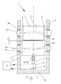
- the system shown is an embossing station 1 with the two counter-rotating rollers 2, 3.
- the in the common Frame 4 at the top arranged roll 2 is in this case provided with embossing points embossing roller, while it is at the bottom arranged roll 3 is a smooth counter embossing roller.
- the two rollers 2, 3 are rotatably mounted in their common frame 4 with their bearing journals 2 a and 3 a in a conventional manner in corresponding bearings 2 b and 3 b, respectively.
- the roller 2 rolls with its so-called support rings (also known as “bearer rings") 6 on the lateral surface 3 'of the roller 3.
- These support rings 6 protrude radially beyond the other surface 2 'of the roller 2, so that a correspondingly defined embossing gap 5 forms in the middle region between the rollers 2, 3, through which the material to be processed is usually guided in the form of a material web.
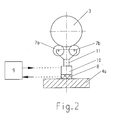
- a strut 11 is disposed in the axially central region below the embossing roller 3, which, as in FIG. 2 can be seen, via two rollers 7a, 7b with the lateral surface 3 'of the roller 3 is in contact. With its bottom facing away from the roller 3, the strut 11 is supported on a bottom plate 4 a of the frame 4 of the embossing station 1.
- FIG. 2 shows, the two rollers 7a, 7b with respect.
- the position of the strut 11 are arranged symmetrically in order to achieve a more uniform distribution of the forces and a stable equilibrium position.
- a sensor 8 and an actuator 10 are arranged, which communicate with each other via a regulator 9.
- This generates a control signal from the transmitted vibration data and supplies this to the actuator 10, in the present case in the form of a piezoelectric element.
- the actuator 10 Based on the control signal generated by the controller 9, the actuator 10 then acts on the lateral surface 3 'of the roller 3 via the rollers 7a, 7b with a force counteracting the vibration.
- the strut 11 simultaneously serves as a support for the central region of the roller 3 and thus indirectly for the roller 2, the proportion of the embossing bends brought about by the own weight of the rollers 2,3 can be reduced or possibly compensated. so that essentially the in Fig. 1 shown symmetrical bending lines B1 and B2 result.
- the controller 9 In operation of the embossing station 1, the controller 9 is initially preset in dependence on external, predetermined parameters. Due to its adaptive functionality, the controller 9 subsequently adapts to the oscillations of the rollers 2, 3 actually occurring and detected by the sensor 8, and ensures optimum damping of the oscillation by the actuator 10.
Landscapes
- Engineering & Computer Science (AREA)
- General Engineering & Computer Science (AREA)
- Physics & Mathematics (AREA)
- Acoustics & Sound (AREA)
- Aviation & Aerospace Engineering (AREA)
- Mechanical Engineering (AREA)
- Machines For Manufacturing Corrugated Board In Mechanical Paper-Making Processes (AREA)
- Shaping Of Tube Ends By Bending Or Straightening (AREA)
- Vibration Prevention Devices (AREA)
Abstract
Description
Die vorliegende Erfindung bezieht sich auf eine Vorrichtung sowie auf ein Verfahren zur aktiven Schwingungsdämpfung insbesondere periodisch auftretender Schwingungen bei gegenläufig rotierenden Walzen wie Prägewalzen, Druckwalzen oder Schneidwalzen.The present invention relates to a device and to a method for active vibration damping in particular periodically occurring vibrations in counter-rotating rollers such as embossing rollers, pressure rollers or cutting rollers.
Während des Betriebs gegenläufig rotierender Walzen kann es zu unerwünschten Schwingungen der Walzen kommen, die die Qualität des zwischen den Walzen stattfindenden Bearbeitungsschritts negativ beeinflussen können.During the operation of counter-rotating rolls, undesirable vibrations of the rolls can occur, which can adversely affect the quality of the processing step taking place between the rolls.
Gegenläufig rotierende Walzen werden beispielsweise bei Prägeverfahren, Druckverfahren oder rotativen Schneideverfahren verwendet. Hierbei wird zwischen die Walzen jeweils eine entsprechende Materialbahn geführt, die dann je nach dem angewendeten Verfahren geprägt, bedruckt, gerillt, perforiert oder geschnitten wird.Counter rotating rolls are used for example in stamping, printing or rotary cutting processes. In this case, a corresponding material web is guided between the rollers, which is then embossed, printed, grooved, perforated or cut depending on the method used.
Insbesondere bei der Verwendung des Einprägens eines Prägemusters in eine Materialbahn oder einzelne Zuschnitte, beispielsweise im Zusammenhang mit Tissueservietten oder Tissuetaschentüchern, die aus mehreren Lagen Tisssuepapier bestehen und deren Tissuelagen durch Verprägen miteinander zusammengehalten werden, treten aufgrund der Prägekräfte im Wesentlichen periodische Schwingungen auf, die sich unter anderem auf die Qualität des Prägemusters auswirken. Dieses auch als "Rattern" bezeichnete Phänomen führt zur ungleichen Ausprägung der Produkte.In particular when using the embossing of an embossing pattern in a material web or individual blanks, for example in connection with tissue napkins or tissue handkerchiefs, which consist of several layers of tissue paper and whose tissue layers are held together by embossing As a result of the embossing forces, essentially periodic oscillations occur, which, among other things, affect the quality of the embossing pattern. This phenomenon, also known as "rattling", leads to uneven expression of the products.
Dieser Problematik kann durch verschiedene, im Stand der Technik bekannte Vorrichtungen und/oder Verfahren entgegengewirkt werden, wobei diese jedoch mit den unterschiedlichsten Nachteilen verbunden sind.This problem can be counteracted by various known in the art devices and / or methods, but these are associated with a variety of disadvantages.
Beispielsweise können besondere, anregungsarme Prägemuster verwendet werden. Dies hat jedoch den Nachteil, dass der Benutzer aufgrund der festgelegten Prägemuster nur einen eingeschränkten Gestaltungsgrad bei der Herstellung eines Produktes hat.For example, special, low-stimulus embossing patterns can be used. However, this has the disadvantage that the user has only a limited degree of design in the manufacture of a product due to the defined embossing patterns.
Auch ist es möglich, die in der Materialbahn gegebenenfalls nebeneinander liegenden Einzelbahnen zueinander zu versetzen, um einen gleichzeitigen Eingriff mehrerer Querprägungen zu vermeiden. Auch diese Lösung ist nur beschränkt einsetzbar und verringert die Gestaltungsfreiheit des Benutzers hinsichtlich der Wahl der Prägemuster.It is also possible to offset the individual webs, which may be adjacent to one another in the material web, in order to avoid a simultaneous engagement of a plurality of transverse embossments. Also, this solution is only limited use and reduces the freedom of the user in terms of choice of embossing patterns.
Weiterhin können die Höhen der Prägepunkte auf der Prägewalze unterschiedlich hoch ausgebildet werden, wobei dies bei gleich bleibender Qualität der Prägung nur gleichzeitig mit einem Einsatz vertiefter Innenfelder auf der Prägewalze möglich ist. Dies bedingt jedoch unausweichlich einen höheren Aufwand bei der Herstellung der Walzen.Furthermore, the heights of the embossing points on the embossing roller can be made of different heights, and this is possible only with simultaneous use of recessed inner fields on the embossing roller while maintaining the quality of the embossing. However, this inevitably requires a higher cost in the production of the rolls.
Neben diesen Möglichkeiten wird im Stand der Technik auch ein Verfahren bzw. eine Vorrichtung vorgeschlagen, bei dem die Prägewalzen einen geschichteten Aufbau aufweisen. Hierbei wird zwischen einen Grundkörper und der die Mantelfläche bildenden Hülse der Walze eine dämpfende Gummischicht eingebracht. Auch dies bringt jedoch einen ungleich höheren Aufwand bei der Herstellung der Walzen mit sich.In addition to these possibilities, a method or a device is proposed in the prior art, in which the embossing rollers have a layered structure. In this case, a damping rubber layer is introduced between a main body and the shell of the roller forming the lateral surface. However, this also brings a much higher cost in the production of rolls with it.
Schließlich existieren zur Schwingungsdämpfung bei gegenläufig rotierenden Walzen auch diverse aktive Schwingungsdämpfungssysteme.Finally, there are various active vibration damping systems for vibration damping in counter-rotating rollers.
So wird beispielsweise in der
Auch in der
Die bekannten Lösungen haben sich jedoch bezüglich ihrer Effizienz nicht als hinreichend befriedigend erwiesen. Dies kann möglicherweise auch als Grund dafür angesehen werden, dass im Bereich von Tissuemaschinen bisher nach Kenntnis der Anmelderin keine aktiven Dämpfungssysteme eingesetzt wurden.However, the known solutions have not proven to be sufficiently satisfactory in terms of their efficiency. This may possibly also be considered to be the reason why, to the knowledge of the Applicant, no active damping systems have been used in the field of tissue machines.
Es ist daher die Aufgabe der vorliegenden Erfindung, eine Vorrichtung und ein Verfahren zur aktiven Schwingungsdämpfung zweier gegenläufig rotierender Walzen zu schaffen, die/das zu einer effektiveren Verringerung der im Prozess auftretenden Schwingungen führt.It is therefore the object of the present invention to provide an apparatus and a method for the active vibration damping of two counter-rotating rollers, which leads to a more effective reduction of the vibrations occurring in the process.
Diese Aufgabe wird mittels einer Vorrichtung und mittels eines Verfahrens mit den Merkmalen der Ansprüche 1 und 8 gelöst. Weitere Ausgestaltungen der vorliegenden Erfindung ergeben sich aus den Unteransprüchen.This object is achieved by means of a device and by means of a method having the features of
Erfindungsgemäß wird vorgeschlagen, die beim Betrieb auftretenden Schwingungen an wenigstens einer Walze mit wenigstens einem Sensor zu erfassen und die erfassten Schwingungsdaten an einen Regler zu übergeben. Anhand der Schwingungsdaten ermittelt der Regler wenigstens ein entsprechendes Steuersignal und übergibt dieses/diese an wenigstens einen Aktor, der daraufhin wenigstens eine Walze mit einer der Schwingung entgegenwirkenden Kraft beaufschlagt. Der Aktor wirkt dabei auf die Mantelfläche der entsprechenden Walze/n ein.According to the invention, it is proposed to detect the vibrations occurring during operation on at least one roller with at least one sensor and to transfer the detected vibration data to a controller. Based on the vibration data, the controller determines at least one corresponding control signal and transfers this / these to at least one actuator, which then acts on at least one roller with a force counteracting the vibration. The actuator acts on the lateral surface of the corresponding roller / n.
Hierbei können auch die Schwingungen beider Walzen mit zwei getrennten Sensoren erfasst und an denselben oder an zwei verschiedene Regler übergegeben werden. Der gemeinsame Regler beziehungsweise die beiden Regler können dann voneinander unabhängig oder in einer definierten Abhängigkeit voneinander Steuersignale erzeugen. Die erzeugten Steuersignale können dann dazu verwendet werden, einen beziehungsweise mehrere Aktoren, der/die entweder nur auf eine Walze oder aber auch auf beide Walzen einwirkt/einwirken anzusteuern.Here, the vibrations of both rollers can be detected with two separate sensors and passed to the same or to two different controller. The common controller or the two controllers can then generate control signals from each other independently or in a defined dependency on one another. The generated control signals can then be used to control one or more actuators acting on only one roller or on both rollers.
Auch wäre es denkbar, dass für jede Walze mehrere Sensoren vorhanden sind, um die Schwingungen der Walze zu erfassen.It would also be conceivable that several sensors are present for each roller in order to detect the vibrations of the roller.
Da aber üblicherweise eine Dämpfung der an einer Walze auftretenden Schwingungen sich auch auf Schwingungen des aus beiden Walzen bestehenden Gesamtsystems auswirken, werden vorzugsweise Schwingungen nur an einer der beiden gegenläufig rotierenden Walzen erfasst und auch nur auf eine der Walzen mit einem Aktor eingewirkt. Hierbei muss es sich jedoch nicht zwangsweise um dieselbe Walze handeln.Since, however, usually an attenuation of the vibrations occurring on a roller also affect vibrations of the existing system consisting of two rolls, vibrations are preferably detected only on one of the two counter-rotating rollers and acted only on one of the rollers with an actuator. However, this need not necessarily be the same roller.
Bei den Sensoren kann es sich hierbei um berührungslose Sensoren handeln, die beispielsweise über eine optische Erfassung die jeweilige Lage der Walze/n ermitteln. Vorzugsweise handelt es sich bei den Sensoren jedoch um solche, die mit der entsprechenden Walze in Kontakt stehen und direkt die auf die Walze wirkenden Beschleunigungen und somit die auf die Walze wirkenden Kräfte erfassen.The sensors may be non-contact sensors which determine the respective position of the roller / s by way of optical detection, for example. Preferably, however, the sensors are those which are in contact with the corresponding roller and directly detect the accelerations acting on the roller and thus the forces acting on the roller.
Für den in der erfindungsgemäßen Vorrichtung bzw. in dem erfindungsgemäßen Verfahren verwendeten Regler kommt jeder geeignete Regler in Frage. Insbesondere kann es sich hierbei um einen Regler mit einem nichtlinearen Reglungsverfahren handeln, der darüber hinaus vorteilhafterweise im Sinne einer adaptiven Regelung selbstlernend sein kann.Any suitable controller can be used for the regulator used in the device according to the invention or in the method according to the invention. In particular, this may be a controller with a non-linear control method, which moreover can advantageously be self-learning in the sense of an adaptive control.
Vorzugsweise kann der Regler in diesem Fall in Abhängigkeit von äußeren, vorgegebenen Parametern wie beispielsweise dem zu verarbeitenden Material, der Rotationsgeschwindigkeit, der Stärke des Materials oder dem Prägemuster voreingestellt werden, wobei sich die optimale Regelung im Betrieb dann aufgrund einer entsprechenden Programmierung des Regler selbstständig einstellt.Preferably, the controller can be preset in this case depending on external, predetermined parameters such as the material to be processed, the rotational speed, the thickness of the material or the embossing pattern, the optimal control then automatically adjusts in operation due to a corresponding programming of the controller ,
Als Aktor wird vorzugsweise ein Piezoelement verwendet, wobei jedoch auch andere Lösungen, beispielsweise hydraulisch geregelte Betätigungselemente oder ähnliches denkbar wären.As actuator preferably a piezoelectric element is used, but other solutions, such as hydraulically controlled actuators or the like would be conceivable.
Vorzugsweise ist der Aktor so angeordnet, dass er axial gesehen im Wesentlichen in der Walzenmitte auf die Mantelfläche der entsprechenden Walze/n einwirkt. Auf diese Weise kann eine symmetrische Krafteinleitung erreicht werden.Preferably, the actuator is arranged so that it acts axially seen in the center of the roll on the lateral surface of the corresponding roller / n. In this way, a symmetrical force application can be achieved.
Für den Fall mehrerer auf eine Walze wirkender Aktoren sind diese vorzugsweise bzgl. der axialen Richtung symmetrisch angeordnet.In the case of a plurality of actuators acting on a roller, these are preferably arranged symmetrically with respect to the axial direction.
Bei einer bevorzugten Ausführungsform sind der Sensor und/oder der Aktor in einer Strebe angeordnet, die vorteilhafterweise über wenigstens zwei Laufrollen mit der entsprechenden Walze in Kontakt steht. Der in der Strebe angeordnete Aktor wirkt dann über die Laufrollen auf die Mantelfläche der entsprechenden Walze ein. Vorzugsweise sind die Laufrollen zur besseren Verteilung der wirkenden Kräfte symmetrische bezüglich der Strebe angeordnet.In a preferred embodiment, the sensor and / or the actuator are arranged in a strut, which is advantageously in contact with the corresponding roller via at least two rollers. The arranged in the strut actuator then acts on the rollers on the lateral surface of the corresponding roller. Preferably, the rollers for better distribution of the forces acting symmetrical with respect to the strut are arranged.
Im Falle von Walzen, die im Wesentlichen vertikal übereinander liegend angeordnet sind oder deren Anordnung zueinander wenigstens eine vertikale Komponente aufweist, kann die Strebe vorzugsweise so angeordnet sein, dass sie sich im Wesentlichen vertikal unterhalb der weiter unten angeordneten Walze befindet oder zumindest bezüglich dieser ebenfalls eine vertikale Komponente aufweist, und die weiter unten angeordneten Walze auf diese Weise unterstützend lagert. Hierbei können die Laufrollen im Querschnitt gesehen dann vorzugsweise symmetrisch um den untersten Punkt der Mantelfläche der Walze angeordnet sein.In the case of rolls which are arranged substantially vertically one above the other or whose arrangement to one another has at least one vertical component, the strut may preferably be arranged so that it is located substantially vertically below the roller arranged below or at least also with respect to this one vertical component, and supports the lower roller arranged in this way supportive. Here, the rollers can be seen in cross section then preferably arranged symmetrically about the lowest point of the lateral surface of the roller.
Auf der der Walze gegenüberliegenden Seite ist die Strebe vorzugsweise auf einer Grundplatte des Walzensystems bzw. dem Boden abgestützt. Eine derartige Anordnung der Strebe führt dazu, dass die Strebe die untere Walze von unten unterstützt und lagert.On the opposite side of the roller, the strut is preferably supported on a base plate of the roller system or the ground. Such an arrangement of the strut causes the strut to support and support the lower roller from below.
Falls die Strebe vorzugsweise axial gesehen in der Mitte des Walzenkörpers angeordnet ist, ergibt sich dann eine mittlere Auflagerung des Walzenkörpers, wodurch die aufgrund des Eigengewichts auftretende Durchbiegung des Walzenkörpers nach unten zumindest teilweise ausgeglichen werden kann.If the strut is preferably arranged axially in the center of the roller body, then a mean bearing of the roller body results, whereby the deflection of the roller body occurring due to the dead weight can be at least partially compensated downwards.
Natürlich wäre es hier auch denkbar, mehrere in Axialrichtung der entsprechenden Walze voneinander beabstandete Streben mit Aktoren und/oder Sensoren zu verwenden, wobei diese dann vorzugsweise symmetrisch zur axialen Mitte der Walze angeordnet sind.Of course, it would also be conceivable here to use a plurality of struts with actuators and / or sensors spaced apart from one another in the axial direction of the corresponding roller, these then preferably being arranged symmetrically to the axial center of the roller.
In einer bevorzugten Ausführungsform handelt es sich bei den beiden Walzen um eine Prägewalze und eine glatte Gegenprägewalze, wobei der Aktor auf die Gegenprägewalze einwirkt. Dies hat den Vorteil, dass die Mantelfläche der Walze, auf die der Aktor einwirkt, glatt ist, so dass bei der Beaufschlagung der Walze mit Kraft keine Oberflächenstruktur der Mantelfläche berücksichtigt werden muss.In a preferred embodiment, the two rollers are an embossing roller and a smooth counter embossing roller, wherein the actuator acts on the counter embossing roller. This has the advantage that the lateral surface of the roller, on which the actuator acts, is smooth, so that no surface structure of the lateral surface must be taken into account when the roller is subjected to force.
Wie bereits oben erwähnt wurde, ist die Anwendung der erfindungsgemäßen Vorrichtung bzw. des erfindungsgemäßen Verfahrens nicht auf Prägewalzen beschränkt, vielmehr ist auch eine Anwendung auf Druckwalzen oder Schneidwalzen möglich.As already mentioned above, the application of the device according to the invention or the method according to the invention is not limited to embossing rollers, but also an application to pressure rollers or cutting rollers is possible.
Nachfolgend wird eine Ausführungsform der vorliegenden Erfindung beispielhaft anhand der beigefügten Zeichnungen beschrieben. Es zeigen:
- Fig. 1:
- eine Aufsicht auf eine Ausführungsform einer erfindungsgemäßen Vorrichtung zur aktiven Schwingungsdämpfung im Fall eines Systems aus zwei gegenläufig rotierenden Prägewalzen und
- Fig. 2:
- einen Querschnitt des in
Figur 1 dargestellten Systems entlang der Linie A-A, wobei aus Gründen der Übersichtlichkeit nur die untere Walze sowie die auf diese wirkende erfindungsgemäße Vorrichtung dargestellt sind.
- Fig. 1:
- a plan view of an embodiment of an inventive device for active vibration damping in the case of a system of two counter-rotating embossing rollers and
- Fig. 2:
- a cross section of the in
FIG. 1 shown system along the line AA, wherein for reasons of clarity, only the lower roller and acting on this device according to the invention are shown.
Bei dem in
Die beiden Walzen 2,3 sind in ihrem gemeinsamen Rahmen 4 mit ihren Lagerzapfen 2a bzw. 3a auf herkömmliche Weise in entsprechenden Lagern 2b beziehungsweise 3b rotierbar gelagert. Im Randbereich der jeweiligen Mantelflächen 2',3' der Walzen 2,3 rollt die Walze 2 mit ihren sogenannten Stützringen (auch als "Schmitzringe" bekannt) 6 auf der Mantelfläche 3' der Walze 3 ab. Diese Stützringe 6 stehen in Radialrichtung über die sonstige Mantelfläche 2' der Walze 2 vor, so dass sich im mittleren Bereich zwischen den Walzen 2,3 ein entsprechend definierter Prägespalt 5 bildet, durch den das zu bearbeitende Material üblicherweise in Form einer Materialbahn geführt wird.The two
Die durch den Prägevorgang auf die Walzen 2,3 wirkende Verformung ist in
Bei der in
Wie sich aus
In der Strebe 11 sind ein Sensor 8 und ein Aktor 10 angeordnet, die über einen Regler 9 miteinander in Verbindung stehen. Hierbei werden die im Betrieb auf die Walze 3 wirkenden Schwingbeschleunigungen vom Sensor 8 erfasst und an den Regler 9 übergeben. Dieser erzeugt aus den übergebenen Schwingungsdaten ein Steuersignal und führt dieses dem Aktor 10, vorliegend in Form eines Piezoelements, zu. Auf Basis des vom Regler 9 erzeugten Steuersignals beaufschlagt der Aktor 10 dann die Mantelfläche 3' der Walze 3 über die Laufrollen 7a,7b mit einer der Schwingung entgegenwirkenden Kraft.In the
Da bei der dargestellten Ausführungsform die Strebe 11 gleichzeitig als Auflage für den mittleren Bereich der Walze 3 und somit mittelbar auch für die Walze 2 dient, kann der durch das Eigengewicht der Walzen 2,3 bewirkte Anteil der Prägebiegungen reduziert bzw. ggf. ausgeglichen werden, so dass sich im wesentlichen die in
Im Betrieb der Prägestation 1 wird der Regler 9 zunächst in Abhängigkeit von äußeren, vorgegebenen Parametern voreingestellt. Aufgrund seiner adaptiven Funktionalität passt sich der Regler 9 im weiteren Verlauf dann an die tatsächlich auftretenden und vom Sensor 8 erfassten Schwingungen der Walzen 2,3 an und stellt eine optimale Dämpfung der Schwingung durch den Aktor 10 sicher.In operation of the embossing station 1, the
- 11
- Prägestationembossing station
- 22
- Prägewalzeembossing roller
- 2'2 '
- Mantelfläche von 2Lateral surface of 2
- 2a2a
- Lagerzapfen von 2Journal of 2
- 2b2 B
- Lager von 2Stock of 2
- 33
- GegenprägewalzeAgainst the embossing roller
- 3'3 '
- Mantelfläche von 3Lateral surface of 3
- 3a3a
- Lagerzapfen von 3Bearing journals of 3
- 3b3b
- Lager von 3Warehouse of 3
- 44
- Rahmenframe
- 4a4a
- Bodenplattebaseplate
- 55
- Prägespaltembossing gap
- 66
- Stützringesupporting rings
- 7a,b7a, b
- Laufrollencastors
- 88th
- Sensorsensor
- 99
- Reglerregulator
- 1010
- Aktoractuator
- 1111
- Strebestrut
- B1B1
- Biegelinie von 2Bend line of 2
- B2B2
- Biegelinie von 3Bend line of 3
Claims (10)
der Aktor (10) derart angeordnet ist, dass er auf die Mantelfläche (3') der entsprechenden Walze/n (3) einwirkt.Device for active vibration damping of two counter-rotating rollers (2,3) comprising
the actuator (10) is arranged such that it acts on the lateral surface (3 ') of the corresponding roller (s) (3).
dadurch gekennzeichnet, dass
der Aktor (10) derart angeordnet ist, dass er axial gesehen im Wesentlichen in der Walzenmitte auf die Mantelfläche (3') der entsprechenden Walze/n (3) einwirkt.Device according to claim 1,
characterized in that
the actuator (10) is arranged such that, viewed axially, it acts on the lateral surface (3 ') of the corresponding roller (s) (3) substantially in the center of the roller.
dadurch gekennzeichnet, dass
der Sensor (8) und/oder der Aktor (10) in einer Strebe (11) angeordnet sind, die über wenigstens zwei Laufrollen (7a,7b) mit der entsprechenden Walze (3) in Kontakt steht.Device according to one of the preceding claims
characterized in that
the sensor (8) and / or the actuator (10) are arranged in a strut (11) which is in contact with the corresponding roller (3) via at least two rollers (7a, 7b).
dadurch gekennzeichnet, dass
im Falle von Walzen (2,3), deren Anordnung zueinander eine vertikale Komponente aufweist, die Strebe (11) derart angeordnet ist, dass sie bezüglich der weiter unten angeordneten Walze (3) ebenfalls eine vertikale Komponente aufweist und die weiter unten angeordneten Walze (3) unterstützend lagert.Device according to claim 3,
characterized in that
in the case of rolls (2, 3) whose arrangement with respect to one another has a vertical component, the strut (11) is arranged such that it also has a vertical component with respect to the roll (3) arranged further down, and the roll arranged below (FIG. 3) supports.
dadurch gekennzeichnet, dass
es sich bei den beiden Walzen (2,3) um eine Prägewalze (2) und eine glatte Gegenprägewalze (3) handelt, wobei der Aktor (10) auf die Gegenprägewalze (3) einwirkt.Device according to one of the preceding claims,
characterized in that
the two rollers (2, 3) are an embossing roller (2) and a smooth counter embossing roller (3), wherein the actuator (10) acts on the counter embossing roller (3).
dadurch gekennzeichnet, dass
es sich bei dem Aktor (10) um ein Piezoelement handelt.Device according to one of the preceding claims,
characterized in that
it is in the actuator (10) is a piezoelectric element.
dadurch gekennzeichnet, dass
der Regler (9) in Abhängigkeit von äußeren vorgegebenen Parametern einstellbar ist.Device according to one of the preceding,
characterized in that
the controller (9) is adjustable in dependence on external predetermined parameters.
wenigstens ein Aktor (10) auf die Mantelfläche (3') der entsprechenden Walze/n (3) einwirkt.Method for active vibration damping of two counter-rotating rollers (2, 3) comprising the steps of
at least one actuator (10) acts on the lateral surface (3 ') of the corresponding roller (s) (3).
dadurch gekennzeichnet, dass
wenigstens ein Aktor (10) axial gesehen im Wesentlichen in der Walzenmitte auf die Mantelfläche (3') der entsprechenden Walze/n (3) einwirkt.Method according to claim 8,
characterized in that
at least one actuator (10) axially acting on the lateral surface (3 ') of the corresponding roller / n (3) substantially in the middle of the roll.
dadurch gekennzeichnet, dass
der Regler (9) in Abhängigkeit von äußeren vorgegebenen Parametern voreingestellt wird und sich seine optimale Regelung im Betrieb aufgrund einer entsprechenden adaptiven Programmierung des Reglers (9) selbständig einstellt.Method according to claim 8 or claim 9,
characterized in that
the controller (9) is preset as a function of external predetermined parameters and its optimum control is automatically set during operation on the basis of a corresponding adaptive programming of the controller (9).
Applications Claiming Priority (1)
| Application Number | Priority Date | Filing Date | Title |
|---|---|---|---|
| DE102007006683A DE102007006683A1 (en) | 2007-02-10 | 2007-02-10 | Device and method for active vibration damping in counter-rotating rollers |
Publications (2)
| Publication Number | Publication Date |
|---|---|
| EP1961992A2 true EP1961992A2 (en) | 2008-08-27 |
| EP1961992A3 EP1961992A3 (en) | 2011-07-27 |
Family
ID=39595767
Family Applications (1)
| Application Number | Title | Priority Date | Filing Date |
|---|---|---|---|
| EP08002352A Withdrawn EP1961992A3 (en) | 2007-02-10 | 2008-02-08 | Device and method for active oscillation attenuation for rollers rotating in opposite directions |
Country Status (2)
| Country | Link |
|---|---|
| EP (1) | EP1961992A3 (en) |
| DE (1) | DE102007006683A1 (en) |
Cited By (2)
| Publication number | Priority date | Publication date | Assignee | Title |
|---|---|---|---|---|
| EP2450592A3 (en) * | 2010-11-05 | 2015-06-17 | United Technologies Corporation | Dampening device |
| WO2017050493A1 (en) * | 2015-09-23 | 2017-03-30 | Sms Group Gmbh | Roll stand, rolling system and method for actively damping vibrations in a roll stand |
Families Citing this family (1)
| Publication number | Priority date | Publication date | Assignee | Title |
|---|---|---|---|---|
| DE102014113810B4 (en) * | 2014-09-24 | 2017-06-08 | Océ Printing Systems GmbH & Co. KG | A method for damping an oscillation of a driven roller in a printing system |
Citations (2)
| Publication number | Priority date | Publication date | Assignee | Title |
|---|---|---|---|---|
| DE10107135A1 (en) | 2001-02-15 | 2002-08-29 | Windmoeller & Hoelscher | Vibration damping in web-fed flexographic printing machine by applying damping forces to rollers in opposite direction to detected offsets |
| DE102005058786A1 (en) | 2004-12-10 | 2006-06-14 | Koenig & Bauer Ag | Vibration reduction method e.g. for damping vibration of cylinder of strip-processing machine, involves determining functional correlation for force course of channel passage through nip point formed by second cylinder |
Family Cites Families (7)
| Publication number | Priority date | Publication date | Assignee | Title |
|---|---|---|---|---|
| DE4241267A1 (en) * | 1992-12-08 | 1994-06-09 | Froehling Josef Gmbh | Multi-roll stand |
| FR2723413B1 (en) * | 1994-08-03 | 1996-10-25 | Patin Pierre | METHOD AND DEVICE FOR AVOIDING VIBRATION OF A LONG LENGTH SHAFT |
| NL1010366C2 (en) * | 1998-10-21 | 2000-04-25 | Hoogovens Corporate Services B | Device for precise position control of a power transmission system. |
| DE10250863B4 (en) * | 2002-10-31 | 2005-06-02 | Brückner Maschinenbau GmbH | Winding device for web-shaped materials, in particular plastic films |
| DE10305433B4 (en) * | 2003-02-11 | 2007-12-06 | Koenig & Bauer Aktiengesellschaft | Rubber cylinder with vibration damping |
| AT500766B1 (en) * | 2003-03-10 | 2008-06-15 | Voest Alpine Ind Anlagen | METHOD AND DEVICE FOR AVOIDING VIBRATIONS |
| DE102005035138A1 (en) * | 2005-07-22 | 2007-01-25 | Bielomatik Leuze Gmbh + Co.Kg | Cross cutter with vibration damping |
-
2007
- 2007-02-10 DE DE102007006683A patent/DE102007006683A1/en not_active Withdrawn
-
2008
- 2008-02-08 EP EP08002352A patent/EP1961992A3/en not_active Withdrawn
Patent Citations (2)
| Publication number | Priority date | Publication date | Assignee | Title |
|---|---|---|---|---|
| DE10107135A1 (en) | 2001-02-15 | 2002-08-29 | Windmoeller & Hoelscher | Vibration damping in web-fed flexographic printing machine by applying damping forces to rollers in opposite direction to detected offsets |
| DE102005058786A1 (en) | 2004-12-10 | 2006-06-14 | Koenig & Bauer Ag | Vibration reduction method e.g. for damping vibration of cylinder of strip-processing machine, involves determining functional correlation for force course of channel passage through nip point formed by second cylinder |
Cited By (5)
| Publication number | Priority date | Publication date | Assignee | Title |
|---|---|---|---|---|
| EP2450592A3 (en) * | 2010-11-05 | 2015-06-17 | United Technologies Corporation | Dampening device |
| WO2017050493A1 (en) * | 2015-09-23 | 2017-03-30 | Sms Group Gmbh | Roll stand, rolling system and method for actively damping vibrations in a roll stand |
| CN108136459A (en) * | 2015-09-23 | 2018-06-08 | Sms集团有限公司 | Rolling-mill housing, rolling equipment and the method for initiatively weakening the vibration in rolling-mill housing |
| CN108136459B (en) * | 2015-09-23 | 2021-06-18 | Sms集团有限公司 | Rolling mill stand, rolling equipment and method for actively damping vibrations in a rolling mill stand |
| US11123781B2 (en) | 2015-09-23 | 2021-09-21 | Sms Group Gmbh | Roll stand, rolling system and method for actively damping vibrations in a roll stand |
Also Published As
| Publication number | Publication date |
|---|---|
| EP1961992A3 (en) | 2011-07-27 |
| DE102007006683A1 (en) | 2008-08-28 |
Similar Documents
| Publication | Publication Date | Title |
|---|---|---|
| WO2008043497A1 (en) | Cutting and/or embossing station | |
| EP1483444A1 (en) | Method and device for reducing vibrations in rotating components | |
| DE3004913A1 (en) | CALENDER | |
| EP1392918B1 (en) | Device, method and arrangement for pressing two axis-parallel rollers approachable to one another in a device for producing and/or treating a web of material | |
| EP1961992A2 (en) | Device and method for active oscillation attenuation for rollers rotating in opposite directions | |
| DE19936278C2 (en) | embossing station | |
| EP1275774B1 (en) | Process for operating a calender and calender | |
| EP2195485A1 (en) | Calender and intermediate calender roller | |
| EP3934997B1 (en) | Driving of a roll slitting machine | |
| DE102018104553A1 (en) | web guide | |
| DE102005016779A1 (en) | Flat multilayer commodity punching device for use in printing machine, has punching and counter punching cylinders, in which one is held in radially shiftable magnetic bearing to adjust breadth of punching gap between cylinders | |
| DE19745216A1 (en) | Air bearing with locally fixed and movable bearing bodies | |
| EP1088779B1 (en) | Method for winding a material web | |
| EP1275777B1 (en) | Process for operating a calender | |
| DE19819663B4 (en) | Roller with reduction of concentricity error | |
| EP2055658A2 (en) | Method and device for coiling a strip of material up into a roll of material | |
| EP1333123B1 (en) | Method and device for active damping of vibrations in a device for treating a continuously moving web | |
| EP1683749B1 (en) | Double support roller winding machine | |
| DE202018101098U1 (en) | web guide | |
| EP1333122B2 (en) | Active vibration-damping method | |
| EP2502861B1 (en) | Device and method for winding a sheet of material | |
| DE102024119652A1 (en) | Feed conveyor for strip material | |
| EP1582625B1 (en) | Extended nip calender and method for treatment of a web in an extended nip | |
| DE202008014463U1 (en) | Reel winding device | |
| EP2128337B1 (en) | Method for operating a calender and same |
Legal Events
| Date | Code | Title | Description |
|---|---|---|---|
| PUAI | Public reference made under article 153(3) epc to a published international application that has entered the european phase |
Free format text: ORIGINAL CODE: 0009012 |
|
| AK | Designated contracting states |
Kind code of ref document: A2 Designated state(s): AT BE BG CH CY CZ DE DK EE ES FI FR GB GR HR HU IE IS IT LI LT LU LV MC MT NL NO PL PT RO SE SI SK TR |
|
| AX | Request for extension of the european patent |
Extension state: AL BA MK RS |
|
| PUAL | Search report despatched |
Free format text: ORIGINAL CODE: 0009013 |
|
| AK | Designated contracting states |
Kind code of ref document: A3 Designated state(s): AT BE BG CH CY CZ DE DK EE ES FI FR GB GR HR HU IE IS IT LI LT LU LV MC MT NL NO PL PT RO SE SI SK TR |
|
| AX | Request for extension of the european patent |
Extension state: AL BA MK RS |
|
| STAA | Information on the status of an ep patent application or granted ep patent |
Free format text: STATUS: THE APPLICATION IS DEEMED TO BE WITHDRAWN |
|
| 18D | Application deemed to be withdrawn |
Effective date: 20110830 |