EP1961992A2 - Procédé et dispositif destinés à l'amortissement actif des vibrations dans des presses rotatives opposées - Google Patents
Procédé et dispositif destinés à l'amortissement actif des vibrations dans des presses rotatives opposées Download PDFInfo
- Publication number
- EP1961992A2 EP1961992A2 EP08002352A EP08002352A EP1961992A2 EP 1961992 A2 EP1961992 A2 EP 1961992A2 EP 08002352 A EP08002352 A EP 08002352A EP 08002352 A EP08002352 A EP 08002352A EP 1961992 A2 EP1961992 A2 EP 1961992A2
- Authority
- EP
- European Patent Office
- Prior art keywords
- roller
- actuator
- rollers
- controller
- vibration
- Prior art date
- Legal status (The legal status is an assumption and is not a legal conclusion. Google has not performed a legal analysis and makes no representation as to the accuracy of the status listed.)
- Withdrawn
Links
- 238000000034 method Methods 0.000 title claims abstract description 19
- 230000010355 oscillation Effects 0.000 title claims description 5
- 238000013016 damping Methods 0.000 claims abstract description 15
- 238000004049 embossing Methods 0.000 claims description 37
- 230000003044 adaptive effect Effects 0.000 claims description 3
- 230000002093 peripheral effect Effects 0.000 abstract 1
- 238000005520 cutting process Methods 0.000 description 3
- 238000004519 manufacturing process Methods 0.000 description 3
- 230000001133 acceleration Effects 0.000 description 2
- 238000005452 bending Methods 0.000 description 2
- 235000004443 Ricinus communis Nutrition 0.000 description 1
- 240000000528 Ricinus communis Species 0.000 description 1
- 230000002411 adverse Effects 0.000 description 1
- 230000001419 dependent effect Effects 0.000 description 1
- 238000001514 detection method Methods 0.000 description 1
- 238000009826 distribution Methods 0.000 description 1
- 230000003287 optical effect Effects 0.000 description 1
- 230000000737 periodic effect Effects 0.000 description 1
- 230000003319 supportive effect Effects 0.000 description 1
- 238000009827 uniform distribution Methods 0.000 description 1
Images
Classifications
-
- F—MECHANICAL ENGINEERING; LIGHTING; HEATING; WEAPONS; BLASTING
- F16—ENGINEERING ELEMENTS AND UNITS; GENERAL MEASURES FOR PRODUCING AND MAINTAINING EFFECTIVE FUNCTIONING OF MACHINES OR INSTALLATIONS; THERMAL INSULATION IN GENERAL
- F16F—SPRINGS; SHOCK-ABSORBERS; MEANS FOR DAMPING VIBRATION
- F16F15/00—Suppression of vibrations in systems; Means or arrangements for avoiding or reducing out-of-balance forces, e.g. due to motion
- F16F15/005—Suppression of vibrations in systems; Means or arrangements for avoiding or reducing out-of-balance forces, e.g. due to motion using electro- or magnetostrictive actuation means
-
- F—MECHANICAL ENGINEERING; LIGHTING; HEATING; WEAPONS; BLASTING
- F16—ENGINEERING ELEMENTS AND UNITS; GENERAL MEASURES FOR PRODUCING AND MAINTAINING EFFECTIVE FUNCTIONING OF MACHINES OR INSTALLATIONS; THERMAL INSULATION IN GENERAL
- F16F—SPRINGS; SHOCK-ABSORBERS; MEANS FOR DAMPING VIBRATION
- F16F15/00—Suppression of vibrations in systems; Means or arrangements for avoiding or reducing out-of-balance forces, e.g. due to motion
- F16F15/02—Suppression of vibrations of non-rotating, e.g. reciprocating systems; Suppression of vibrations of rotating systems by use of members not moving with the rotating systems
Definitions
- the present invention relates to a device and to a method for active vibration damping in particular periodically occurring vibrations in counter-rotating rollers such as embossing rollers, pressure rollers or cutting rollers.
- Counter rotating rolls are used for example in stamping, printing or rotary cutting processes.
- a corresponding material web is guided between the rollers, which is then embossed, printed, grooved, perforated or cut depending on the method used.
- embossing of an embossing pattern in a material web or individual blanks for example in connection with tissue napkins or tissue handkerchiefs, which consist of several layers of tissue paper and whose tissue layers are held together by embossing
- tissue napkins or tissue handkerchiefs which consist of several layers of tissue paper and whose tissue layers are held together by embossing
- essentially periodic oscillations occur, which, among other things, affect the quality of the embossing pattern.
- This phenomenon also known as "rattling” leads to uneven expression of the products.
- the heights of the embossing points on the embossing roller can be made of different heights, and this is possible only with simultaneous use of recessed inner fields on the embossing roller while maintaining the quality of the embossing.
- this inevitably requires a higher cost in the production of the rolls.
- an active damping is provided, are detected at the occurring position deviations of at least one roller and each opposing damping forces are given to the at least one roller.
- the damping forces are generated by means of an actuator, which is controlled as a function of the detected position deviations, wherein the actuator acts on the bearing of the at least one roller.
- the controller determines at least one corresponding control signal and transfers this / these to at least one actuator, which then acts on at least one roller with a force counteracting the vibration.
- the actuator acts on the lateral surface of the corresponding roller / n.
- the vibrations of both rollers can be detected with two separate sensors and passed to the same or to two different controller.
- the common controller or the two controllers can then generate control signals from each other independently or in a defined dependency on one another.
- the generated control signals can then be used to control one or more actuators acting on only one roller or on both rollers.
- vibrations are preferably detected only on one of the two counter-rotating rollers and acted only on one of the rollers with an actuator. However, this need not necessarily be the same roller.
- the sensors may be non-contact sensors which determine the respective position of the roller / s by way of optical detection, for example.
- the sensors are those which are in contact with the corresponding roller and directly detect the accelerations acting on the roller and thus the forces acting on the roller.
- any suitable controller can be used for the regulator used in the device according to the invention or in the method according to the invention.
- this may be a controller with a non-linear control method, which moreover can advantageously be self-learning in the sense of an adaptive control.
- the controller can be preset in this case depending on external, predetermined parameters such as the material to be processed, the rotational speed, the thickness of the material or the embossing pattern, the optimal control then automatically adjusts in operation due to a corresponding programming of the controller ,
- actuator preferably a piezoelectric element is used, but other solutions, such as hydraulically controlled actuators or the like would be conceivable.
- the actuator is arranged so that it acts axially seen in the center of the roll on the lateral surface of the corresponding roller / n. In this way, a symmetrical force application can be achieved.
- actuators acting on a roller these are preferably arranged symmetrically with respect to the axial direction.
- the senor and / or the actuator are arranged in a strut, which is advantageously in contact with the corresponding roller via at least two rollers.
- the arranged in the strut actuator then acts on the rollers on the lateral surface of the corresponding roller.
- the rollers for better distribution of the forces acting symmetrical with respect to the strut are arranged.
- the strut may preferably be arranged so that it is located substantially vertically below the roller arranged below or at least also with respect to this one vertical component, and supports the lower roller arranged in this way supportive.
- the rollers can be seen in cross section then preferably arranged symmetrically about the lowest point of the lateral surface of the roller.
- the strut On the opposite side of the roller, the strut is preferably supported on a base plate of the roller system or the ground. Such an arrangement of the strut causes the strut to support and support the lower roller from below.
- the strut is preferably arranged axially in the center of the roller body, then a mean bearing of the roller body results, whereby the deflection of the roller body occurring due to the dead weight can be at least partially compensated downwards.
- the two rollers are an embossing roller and a smooth counter embossing roller, wherein the actuator acts on the counter embossing roller.
- the application of the device according to the invention or the method according to the invention is not limited to embossing rollers, but also an application to pressure rollers or cutting rollers is possible.
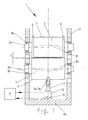
- the system shown is an embossing station 1 with the two counter-rotating rollers 2, 3.
- the in the common Frame 4 at the top arranged roll 2 is in this case provided with embossing points embossing roller, while it is at the bottom arranged roll 3 is a smooth counter embossing roller.
- the two rollers 2, 3 are rotatably mounted in their common frame 4 with their bearing journals 2 a and 3 a in a conventional manner in corresponding bearings 2 b and 3 b, respectively.
- the roller 2 rolls with its so-called support rings (also known as “bearer rings") 6 on the lateral surface 3 'of the roller 3.
- These support rings 6 protrude radially beyond the other surface 2 'of the roller 2, so that a correspondingly defined embossing gap 5 forms in the middle region between the rollers 2, 3, through which the material to be processed is usually guided in the form of a material web.
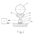
- a strut 11 is disposed in the axially central region below the embossing roller 3, which, as in FIG. 2 can be seen, via two rollers 7a, 7b with the lateral surface 3 'of the roller 3 is in contact. With its bottom facing away from the roller 3, the strut 11 is supported on a bottom plate 4 a of the frame 4 of the embossing station 1.
- FIG. 2 shows, the two rollers 7a, 7b with respect.
- the position of the strut 11 are arranged symmetrically in order to achieve a more uniform distribution of the forces and a stable equilibrium position.
- a sensor 8 and an actuator 10 are arranged, which communicate with each other via a regulator 9.
- This generates a control signal from the transmitted vibration data and supplies this to the actuator 10, in the present case in the form of a piezoelectric element.
- the actuator 10 Based on the control signal generated by the controller 9, the actuator 10 then acts on the lateral surface 3 'of the roller 3 via the rollers 7a, 7b with a force counteracting the vibration.
- the strut 11 simultaneously serves as a support for the central region of the roller 3 and thus indirectly for the roller 2, the proportion of the embossing bends brought about by the own weight of the rollers 2,3 can be reduced or possibly compensated. so that essentially the in Fig. 1 shown symmetrical bending lines B1 and B2 result.
- the controller 9 In operation of the embossing station 1, the controller 9 is initially preset in dependence on external, predetermined parameters. Due to its adaptive functionality, the controller 9 subsequently adapts to the oscillations of the rollers 2, 3 actually occurring and detected by the sensor 8, and ensures optimum damping of the oscillation by the actuator 10.
Landscapes
- Engineering & Computer Science (AREA)
- General Engineering & Computer Science (AREA)
- Physics & Mathematics (AREA)
- Acoustics & Sound (AREA)
- Aviation & Aerospace Engineering (AREA)
- Mechanical Engineering (AREA)
- Machines For Manufacturing Corrugated Board In Mechanical Paper-Making Processes (AREA)
- Shaping Of Tube Ends By Bending Or Straightening (AREA)
- Vibration Prevention Devices (AREA)
Applications Claiming Priority (1)
| Application Number | Priority Date | Filing Date | Title |
|---|---|---|---|
| DE102007006683A DE102007006683A1 (de) | 2007-02-10 | 2007-02-10 | Vorrichtung und Verfahren zur aktiven Schwingungsdämpfung bei gegenläufig rotierenden Walzen |
Publications (2)
| Publication Number | Publication Date |
|---|---|
| EP1961992A2 true EP1961992A2 (fr) | 2008-08-27 |
| EP1961992A3 EP1961992A3 (fr) | 2011-07-27 |
Family
ID=39595767
Family Applications (1)
| Application Number | Title | Priority Date | Filing Date |
|---|---|---|---|
| EP08002352A Withdrawn EP1961992A3 (fr) | 2007-02-10 | 2008-02-08 | Procédé et dispositif destinés à l'amortissement actif des vibrations dans des presses rotatives opposées |
Country Status (2)
| Country | Link |
|---|---|
| EP (1) | EP1961992A3 (fr) |
| DE (1) | DE102007006683A1 (fr) |
Cited By (2)
| Publication number | Priority date | Publication date | Assignee | Title |
|---|---|---|---|---|
| EP2450592A3 (fr) * | 2010-11-05 | 2015-06-17 | United Technologies Corporation | Dispositif d'amortissement |
| WO2017050493A1 (fr) * | 2015-09-23 | 2017-03-30 | Sms Group Gmbh | Cage de laminoir, installation de laminage et procédé pour l'amortissement actif des vibrations dans une cage de laminoir |
Families Citing this family (1)
| Publication number | Priority date | Publication date | Assignee | Title |
|---|---|---|---|---|
| DE102014113810B4 (de) | 2014-09-24 | 2017-06-08 | Océ Printing Systems GmbH & Co. KG | Verfahren zum Dämpfen einer Oszillation einer angetriebenen Walze in einem Drucksystem |
Citations (2)
| Publication number | Priority date | Publication date | Assignee | Title |
|---|---|---|---|---|
| DE10107135A1 (de) | 2001-02-15 | 2002-08-29 | Windmoeller & Hoelscher | Rollendruckmaschine sowie Verfahren zur Schwingungsdämpfung hieran |
| DE102005058786A1 (de) | 2004-12-10 | 2006-06-14 | Koenig & Bauer Ag | Verfahren und eine Vorrichtung zur Schwingungsreduktion eines Zylinders |
Family Cites Families (7)
| Publication number | Priority date | Publication date | Assignee | Title |
|---|---|---|---|---|
| DE4241267A1 (de) * | 1992-12-08 | 1994-06-09 | Froehling Josef Gmbh | Vielwalzengerüst |
| FR2723413B1 (fr) * | 1994-08-03 | 1996-10-25 | Patin Pierre | Procede et dispositif pour eviter les vibrations d'un arbre de grande longueur |
| NL1010366C2 (nl) * | 1998-10-21 | 2000-04-25 | Hoogovens Corporate Services B | Inrichting voor een nauwkeurige positieregeling van een krachtoverbrengend systeem. |
| DE10250863B4 (de) * | 2002-10-31 | 2005-06-02 | Brückner Maschinenbau GmbH | Wickelvorrichtung für bahnförmige Materialien, insbesondere Kunststofffolien |
| DE10305433B4 (de) * | 2003-02-11 | 2007-12-06 | Koenig & Bauer Aktiengesellschaft | Gummizylinder mit Schwingungsdämpfung |
| AT500766B1 (de) * | 2003-03-10 | 2008-06-15 | Voest Alpine Ind Anlagen | Verfahren und vorrichtung zur vermeidung von schwingungen |
| DE102005035138A1 (de) * | 2005-07-22 | 2007-01-25 | Bielomatik Leuze Gmbh + Co.Kg | Querschneider mit Schwingungsdämpfung |
-
2007
- 2007-02-10 DE DE102007006683A patent/DE102007006683A1/de not_active Withdrawn
-
2008
- 2008-02-08 EP EP08002352A patent/EP1961992A3/fr not_active Withdrawn
Patent Citations (2)
| Publication number | Priority date | Publication date | Assignee | Title |
|---|---|---|---|---|
| DE10107135A1 (de) | 2001-02-15 | 2002-08-29 | Windmoeller & Hoelscher | Rollendruckmaschine sowie Verfahren zur Schwingungsdämpfung hieran |
| DE102005058786A1 (de) | 2004-12-10 | 2006-06-14 | Koenig & Bauer Ag | Verfahren und eine Vorrichtung zur Schwingungsreduktion eines Zylinders |
Cited By (5)
| Publication number | Priority date | Publication date | Assignee | Title |
|---|---|---|---|---|
| EP2450592A3 (fr) * | 2010-11-05 | 2015-06-17 | United Technologies Corporation | Dispositif d'amortissement |
| WO2017050493A1 (fr) * | 2015-09-23 | 2017-03-30 | Sms Group Gmbh | Cage de laminoir, installation de laminage et procédé pour l'amortissement actif des vibrations dans une cage de laminoir |
| CN108136459A (zh) * | 2015-09-23 | 2018-06-08 | Sms集团有限公司 | 轧机机架、轧制设备和用于主动地减弱轧机机架中的振动的方法 |
| CN108136459B (zh) * | 2015-09-23 | 2021-06-18 | Sms集团有限公司 | 轧机机架、轧制设备和用于主动地减弱轧机机架中的振动的方法 |
| US11123781B2 (en) | 2015-09-23 | 2021-09-21 | Sms Group Gmbh | Roll stand, rolling system and method for actively damping vibrations in a roll stand |
Also Published As
| Publication number | Publication date |
|---|---|
| DE102007006683A1 (de) | 2008-08-28 |
| EP1961992A3 (fr) | 2011-07-27 |
Similar Documents
| Publication | Publication Date | Title |
|---|---|---|
| WO2008043497A1 (fr) | Poste de coupe et/ou d'estampage | |
| EP1483444A1 (fr) | Procede et dispositif pour reduire des vibrations sur des composants en rotation | |
| DE3004913A1 (de) | Kalander | |
| EP1392918B1 (fr) | Dispositif, procede et systeme destines a comprimer deux cylindres d'axes paralleles pouvant etre rapproches l'un de l'autre dans une installation de fabrication et/ou de traitement d'une bande de materiau | |
| EP1961992A2 (fr) | Procédé et dispositif destinés à l'amortissement actif des vibrations dans des presses rotatives opposées | |
| DE19936278C2 (de) | Prägestation | |
| EP3934997B1 (fr) | Entraînement de machines de découpe de bobines | |
| EP1275774B1 (fr) | Procédé pour le fonctionnement d'une calandre et calandre | |
| EP2195485A1 (fr) | Calandre et cylindre intermediaire de calandre | |
| DE102018104553A1 (de) | Bahnleitvorrichtung | |
| DE102005016779A1 (de) | Vorrichtung und Verfahren zum Stanzen von flachem mehrschichtigem Gut | |
| DE19745216A1 (de) | Luftlager und Verfahren zum Einstellen eines Luftlagers | |
| EP1088779B1 (fr) | Méthode pour enrouler une bande de matériau | |
| EP1275777B1 (fr) | Procédé pour le fonctionnement d'une calandre | |
| DE19819663B4 (de) | Walze mit Verminderung des Rundlauffehlers | |
| EP2055658A2 (fr) | Procédé et dispositif destinés à enrouler une bande de matériau en un rouleau de bande de matériau | |
| EP1333123B1 (fr) | Procédé et dispositif d'amortissement actif dans un dispositif de traitement d'une bande en mouvement continu | |
| EP1683749B1 (fr) | Bobineuse avec cylindres porteurs | |
| EP1333122B2 (fr) | Méthode d'amortissement actif de vibrations | |
| EP2502861B1 (fr) | Dispositif et procédé d'enroulement d'une bande de matériau | |
| DE102024119652A1 (de) | Vorschubfördereinrichtung für Bandmaterial | |
| EP1582625B1 (fr) | Calandre à pince allongée et procédé pour lisser une bande dans un calandre à pince allongée | |
| DE202008014463U1 (de) | Rollenwickeleinrichtung | |
| EP2128337B1 (fr) | Procédé de fonctionnement d'une calandre et calandre | |
| EP2423382A1 (fr) | Dispositif et procédé de réduction de vibrations sur un rouleau à compensation de flèche |
Legal Events
| Date | Code | Title | Description |
|---|---|---|---|
| PUAI | Public reference made under article 153(3) epc to a published international application that has entered the european phase |
Free format text: ORIGINAL CODE: 0009012 |
|
| AK | Designated contracting states |
Kind code of ref document: A2 Designated state(s): AT BE BG CH CY CZ DE DK EE ES FI FR GB GR HR HU IE IS IT LI LT LU LV MC MT NL NO PL PT RO SE SI SK TR |
|
| AX | Request for extension of the european patent |
Extension state: AL BA MK RS |
|
| PUAL | Search report despatched |
Free format text: ORIGINAL CODE: 0009013 |
|
| AK | Designated contracting states |
Kind code of ref document: A3 Designated state(s): AT BE BG CH CY CZ DE DK EE ES FI FR GB GR HR HU IE IS IT LI LT LU LV MC MT NL NO PL PT RO SE SI SK TR |
|
| AX | Request for extension of the european patent |
Extension state: AL BA MK RS |
|
| STAA | Information on the status of an ep patent application or granted ep patent |
Free format text: STATUS: THE APPLICATION IS DEEMED TO BE WITHDRAWN |
|
| 18D | Application deemed to be withdrawn |
Effective date: 20110830 |