EP1962006A1 - Collier de tuyau - Google Patents
Collier de tuyau Download PDFInfo
- Publication number
- EP1962006A1 EP1962006A1 EP07003653A EP07003653A EP1962006A1 EP 1962006 A1 EP1962006 A1 EP 1962006A1 EP 07003653 A EP07003653 A EP 07003653A EP 07003653 A EP07003653 A EP 07003653A EP 1962006 A1 EP1962006 A1 EP 1962006A1
- Authority
- EP
- European Patent Office
- Prior art keywords
- flange
- opening
- pipe clamp
- screw
- bracket
- Prior art date
- Legal status (The legal status is an assumption and is not a legal conclusion. Google has not performed a legal analysis and makes no representation as to the accuracy of the status listed.)
- Granted
Links
Images

Classifications
-
- F—MECHANICAL ENGINEERING; LIGHTING; HEATING; WEAPONS; BLASTING
- F16—ENGINEERING ELEMENTS AND UNITS; GENERAL MEASURES FOR PRODUCING AND MAINTAINING EFFECTIVE FUNCTIONING OF MACHINES OR INSTALLATIONS; THERMAL INSULATION IN GENERAL
- F16L—PIPES; JOINTS OR FITTINGS FOR PIPES; SUPPORTS FOR PIPES, CABLES OR PROTECTIVE TUBING; MEANS FOR THERMAL INSULATION IN GENERAL
- F16L3/00—Supports for pipes, cables or protective tubing, e.g. hangers, holders, clamps, cleats, clips, brackets
- F16L3/08—Supports for pipes, cables or protective tubing, e.g. hangers, holders, clamps, cleats, clips, brackets substantially surrounding the pipe, cable or protective tubing
- F16L3/10—Supports for pipes, cables or protective tubing, e.g. hangers, holders, clamps, cleats, clips, brackets substantially surrounding the pipe, cable or protective tubing divided, i.e. with two members engaging the pipe, cable or protective tubing
- F16L3/1008—Supports for pipes, cables or protective tubing, e.g. hangers, holders, clamps, cleats, clips, brackets substantially surrounding the pipe, cable or protective tubing divided, i.e. with two members engaging the pipe, cable or protective tubing with two members engaging the pipe, cable or tubing, both being made of thin band material completely surrounding the pipe
Definitions
- the present invention relates to a pipe clamp, with a circumferential bracket with one of a first and a second each radially projecting flange limited insertion opening, a fastener and at least one clamped between the flanges clamping screw at its foot by a on the first flange as Long hole trained first opening is held in a pivotably held at the free end of the first flange Einschraubfuß and is hooked with its screw head in a second opening in the second flange, wherein the Einschraubfuß is pivotally held such that the clamping screw from a position normal to the first flange with the screw head is pivotable to the radial inner end of the second opening in the second flange.
- Pipe clamps are used for fastening of pipelines, wherein the pipe to be fastened is usually held in a bow-shaped clamp, which in turn is mounted on a supporting structure. Usually, the installation is done on the wall or ceiling before attaching the pipe. Special attention requires the insertion of the tube in the clamp and the subsequent closing and tightening of the clamp. Since pipe clamps are often mounted overhead on ladders or scaffolding, it is especially important to ensure that no parts can come loose and fall off. Further, those clamps are advantageous in which the clamp can be closed as easily as possible after inserting the tube. Clamp types which allow a one-man assembly, ie where no additional fitters are required for holding the pipe or the clamp, are particularly favorable.
- Example meadow shows the DE 3436710 C2 a captive retaining the Einschraubfußes and screwed into this screw is in the DE 3436710 C2 provided on the one flange a protruding tab which projects through an opening of the attached Einschraubfußes.
- the object of the present invention is to provide a cheap to produce pipe clamp, which simplifies the assembly.
- the object is achieved by a pipe clamp of the type mentioned, in which the Einschraubfuß has a hammer-shaped projection which engages behind the edges of the elongated hole, wherein the cross-section of the hammer-shaped projection can be inserted through the slot opening.
- the advantage of the pipe clamp according to the invention is that the individual parts of the pipe clamp can be prefabricated all initially. For joining then no elaborate, processing steps more required. Since the Einschraubfuß is already held by the engaging behind the opening edges, no separate steps are required.
- the engaging behind the opening edges with the hammer-shaped projection also results in a good pivoting of the clamping screw, so that the fitter can hook the screw head for the temporary closing of the clamp easier.
- the screw head is pivoted inward, ie to the radial inner end of the second opening and introduced there into the second opening, so that the screw head engages behind the lateral edges of the second opening and the pipe clamp is provisionally closed by hooking the screw.
- the first flange has a folded edge pointing away from the insertion opening, wherein the slot extends beyond the folded edge beyond the upper side of the hammer-shaped projection of the screw-in foot resting on the flange. This avoids that the hammer-shaped projection can protrude in the region of the underside of the flanges, with the result that the closing operation of the pipe clamp could be hindered.
- the first and the second flange extend radially and are arranged in the closed state substantially parallel to each other.
- the Einschraubfuß is designed as a flat retaining plate to ensure the best possible initiation of the clamping force of the screw on the Einschraubfuß in the flanges and thus in the pipe clamp.
- the holding plate can be produced inexpensively with a minimum number of steps.
- the retaining plate is held captive after the insertion of a clamping screw on the flange, so that the pipe clamp can already be pre-assembled during manufacture.
- the retaining plate with the screw can not be lost during transport or storage. This results in ease of handling and the fact that the clamp on the site is always complete, also benefits in logistics and warehousing.
- the clamping screw is secured against unscrewing from the Einschraubfuß, for example by deformation of the threaded shaft end, applying an adhesive or setting a weld at the threaded shaft end.
- the hammer-shaped projection serves as a handle or is designed accordingly, wherein by means of the handle, the holding plate is pivotable about its pivot axis manually.
- the clamping screw can be easily hooked into the second opening during assembly by the fitter. This simplifies assembly, especially in a vertical mounting or a lateral mounting of the pipe clamp with upwardly oriented insertion opening when the clamping screw due to its own weight tends to swing away from the insertion. Also, the swinging out of the screw from the position normal to the flanges can be supported manually.
- the hammer-shaped projection protrudes so far that a light force can be applied to it with the fingertip.
- the edges are rounded or at least deburred.
- the second opening extends into the clamp bracket and there goes into an extension, the slightly wider and higher than the screw head is to easily insert the screw head for hooking into the opening.
- the lateral edges of the second opening on the side facing away from the insertion of the second flange before the transition of the second opening in the clamp bracket surveys. Even with a small force acting on the clamp in the opening direction, the elevations reliably prevent accidental slipping out of the screw head. For example, if the tube is inserted into the insertion opening and the pipe clamp is temporarily closed by hooking the screw head, the tube rests on the lower bracket half and pushes them down, which in turn causes the second flange against the screw head is pressed so that it is reliably held by the surveys and can not slip out of the opening.
- the rotating bracket is in two parts and the two bracket halves are articulated relative to the insertion opening.
- the pipe clamp for example, first be attached to the supporting structure and the pipe to be fastened thereafter be inserted into the pipe clamp by the import opening is widened.
- the connection of the two-part bracket can z. B. by a hinge connection, in which a tab of one half engages in a recess of the other half and engages behind the opening edges.
- the two-part bracket is provided on the inside with a one-piece elastic insert, which exerts on the bracket halves a spring force and endeavors, the bracket halves to push apart.
- Elastic inserts are known and take over the sound-technical function to cushion the tube against the support and the supporting structure and to transmit as few vibrations, ie structure-borne noise. Due to the pressed-apart bracket halves, the fitter can insert the pipe to be fastened in the already mounted pipe clamp without first having to expand the insertion of the pipe clamp.
- the invention also relates to a method for producing a pipe clamp according to one of the preceding embodiments.
- the method provides that the Einschraubfuß is introduced with the hammer-shaped projection in the slot on the first flange and then rotated, so that the projection engages behind the edges of the slot.
- the clamping screw is then screwed through the slot in the Einschraubfuß and this secured against falling out.
- a separate operation after assembly such as bending a retaining tab, is no longer necessary. Screwing in the screw ensures that the individual parts can not be lost during transport and storage.
- the screw can be secured after screwing against unscrewing, for example by applying an adhesive at the end of the threaded shaft.
- Fig. 1 shows a clamp in a side view.
- the clamp has a circumferential bracket with an insertion opening 12 for inserting a pipe, not shown, wherein the pipe clamp in Fig. 1 is shown closed.
- the insertion opening 12 can be widened at least to the diameter of the largest tubes, for which the pipe clamp is provided.
- the peripheral bracket consists of a first bracket half 14 and a second bracket half 16, wherein opposite the insertion opening 12, an articulated connection 18 is provided, with which the second bracket half 16 is connected to the first bracket half 14.
- the articulated connection 18 allows pivoting of the bracket halves 14, 16.
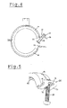
- Fig. 4 are the bracket halves 14, 16, for example, in a slightly open state.
- a fastening element 20 is provided with an internal thread on the first bracket half 14.
- the fastener 20 is formed hexagonally on the outside to a tool, for. B. to set an open-end wrench or pliers.
- the first 14 and the second bracket half 16 are formed at the insertion opening with a first flange 22 and a second flange 24, each projecting radially outwardly, wherein the first flange 22 has a bevelling 26 facing away from the insertion opening 12.
- the two flanges 22, 24 are connected to a clamping screw 28 which is held at its threaded shaft end in a Einschraubfuß 30.
- the clamping screw 28 projects through a formed on the first flange 22 as a slot 32 first opening.
- the head of the clamping screw 28 is in Fig. 1 hooked in a second opening 34 on the second flange 24.
- the Einschraubfuß 30 is pivotally supported at the free end of the first flange 22 so that the clamping screw 28 can be pivoted from a position normal to the first flange 22 with its head to the radially inner end of the second opening 34 in the second flange 24 (see Fig. 4 ).
- a hammer-shaped projection 36 is provided on the Einschraubfuß 30, the cross section is inserted for insertion of the Einschraubfußes 30 through the opening of the elongated hole 32. Thereafter, the hammer-shaped projection 36 is rotated to its final position, in which it engages behind the edges of the slot 32 (see Fig. 3 ).
- the screw-in is exemplified as a flat retaining plate 38 which has a thread and is held captive by screwing the clamping screw 28 to the first flange 22.
- the hammer-shaped projection 36 there are advantages in the production of the pipe clamp according to the invention, since the insertion of the Einschraubfußes usually takes place after the completion of the individual parts and no additional steps are necessary, such as a bending or widening a tab.
- the clamping screw 28 through the Long hole 32 in the first flange 22 is screwed into the Einschraubfuß 30, this is secured against falling out, since the clamping screw 28 limits the freedom of movement of Einschraubfußes.
- the radial inner edge of the slot 32 forms a kind of stop for the shaft of the clamping screw 28.
- Fig. 4 By striking this edge of the Einschraubfuß 30 is prevented from occupying a position in which the hammer-shaped projection 36, the edges of the elongated hole 32 no longer engages behind and moved through the opening of the elongated hole 32 could be.
- the clamping screw 28 After screwing into the Einschraubfuß 30, the clamping screw 28 is provided at the front end of its threaded shaft with some glue, so that the clamping screw 28 can not be unintentionally rotated from the Einschraubfuß 30 out.
- the slot 32 extends beyond the folded edge 26 and extends beyond the top of the hammer-shaped projection 36 of resting on the first flange 22 retaining plate 36, wherein the hammer-shaped projection 36, the opening edges in the region of the folded edge 26 engages behind (see also Fig. 5 ).
- the hammer-shaped projection 36 does not protrude either with flat resting on the first flange 22 holding plate 38 even with a pivoted screw in the area between the first and second flange 22, 24, so that the closing operation is not hindered and the flanges abut each other in a complete closing and be able to pick up and hold pipes with the smallest possible diameter.
- the hammer-shaped projection 36 ensures that the holding plate 38 does not rotate when the clamping screw 28 is screwed in. Since the insertion opening facing away from the first Flange 14, ie the top in Fig. 1 , Is bounded on one side by the folded edge 26 and on the other side by the adjoining first bracket half 14, twisting can alternatively or additionally be prevented by these limitations by the holding plate 38 is formed so large that they play with between the fits both limits and already rests with a slight twisting with their edges on the boundaries.
- the two bracket halves 14, 16 are provided with a one-piece elastic insert 40. This exerts on the two bracket halves 14, 16 a spring force, which holds the bracket halves 14, 16 in an open state when the clamping screw 28 is not hooked yet.
- the insert 40 surrounds the lateral edges of the two brackets 14, 16, so that gluing or otherwise attaching the insert to the brackets is not required.
- the latter In order to hook the head of the clamping screw 28 in the second opening 62, the latter is formed with an extension which is slightly wider and higher than the screw head. In order to pivot the screw with its head in the second opening 21, the second opening 34 projects into the second bracket 16 and there goes over into the extension.
- the lateral edges of the second opening 34 are on the side facing away from the insertion opening 12 of the second flange 24, in Fig. 1 So provided on the bottom, before the transition of the second opening 34 in the second bracket 16 with elevations 42.
- the latter prevent the clamping screw 28 is accidentally pivoted out of the second opening 34 after hooking with her head again.
- the surveys 42 can be z. B. simply by making that each a smaller Section of the edge of the second opening 34 away from the insertion, ie obliquely downwards, is bent. This can be done, for example, during the punching process of the second opening 34.
- the hammer-shaped projection 36 is formed as a handle, by means of which the holding plate 38th is manually pivotable about its pivot axis.
- the installer can easily hook the clamping screw 28 into the second opening 34 by actuating the hammer-shaped projection 36. Since the leverage forces are very low, it is already sufficient if the hammer-shaped projection 36 protrudes so far, that with his fingertip a light force can be applied to him. Conversely, the pivoting of the screw before hooking can be supported manually.
- the edges of the hammer-shaped projection 36 should be rounded or at least deburred.
- the possible use of safety gloves can be taken into account.
- the fitter presses the two bracket halves together slightly.
- the screw head is then applied to the inlet slopes and is pivoted in a further compression inward, ie in the direction of extension. Once it has reached the extension, the screw head is due to gravity, which moves the screw 28 in a vertical position, inserted into the extension and passes behind the surveys 42.
- the fitter now releases the clamp mounted on a supporting ground presses the elastic insert 40, the bracket halves 14, 16 apart. By the projections 42, the screw head is prevented from unintentionally leaving the second opening 34 again.
- the tube is thus provisionally held, so that the fitter can grip the appropriate tool, for. B. a screwdriver to turn the clamping screw 28 in the thread of the holding plate 38 and to tension.
- a screwdriver to turn the clamping screw 28 in the thread of the holding plate 38 and to tension.
Landscapes
- Engineering & Computer Science (AREA)
- General Engineering & Computer Science (AREA)
- Mechanical Engineering (AREA)
- Clamps And Clips (AREA)
- Supports For Pipes And Cables (AREA)
Priority Applications (5)
| Application Number | Priority Date | Filing Date | Title |
|---|---|---|---|
| ES07003653T ES2343143T3 (es) | 2007-02-22 | 2007-02-22 | Abrazadera de tubo. |
| DE502007003298T DE502007003298D1 (de) | 2007-02-22 | 2007-02-22 | Rohrschelle |
| EP07003653A EP1962006B1 (fr) | 2007-02-22 | 2007-02-22 | Collier de tuyau |
| PL07003653T PL1962006T3 (pl) | 2007-02-22 | 2007-02-22 | Zacisk rurowy |
| AT07003653T ATE462916T1 (de) | 2007-02-22 | 2007-02-22 | Rohrschelle |
Applications Claiming Priority (1)
| Application Number | Priority Date | Filing Date | Title |
|---|---|---|---|
| EP07003653A EP1962006B1 (fr) | 2007-02-22 | 2007-02-22 | Collier de tuyau |
Publications (2)
| Publication Number | Publication Date |
|---|---|
| EP1962006A1 true EP1962006A1 (fr) | 2008-08-27 |
| EP1962006B1 EP1962006B1 (fr) | 2010-03-31 |
Family
ID=38246261
Family Applications (1)
| Application Number | Title | Priority Date | Filing Date |
|---|---|---|---|
| EP07003653A Active EP1962006B1 (fr) | 2007-02-22 | 2007-02-22 | Collier de tuyau |
Country Status (5)
| Country | Link |
|---|---|
| EP (1) | EP1962006B1 (fr) |
| AT (1) | ATE462916T1 (fr) |
| DE (1) | DE502007003298D1 (fr) |
| ES (1) | ES2343143T3 (fr) |
| PL (1) | PL1962006T3 (fr) |
Cited By (1)
| Publication number | Priority date | Publication date | Assignee | Title |
|---|---|---|---|---|
| DE102017125194A1 (de) * | 2017-10-27 | 2019-05-02 | Norma Germany Gmbh | Rohrkupplung |
Citations (3)
| Publication number | Priority date | Publication date | Assignee | Title |
|---|---|---|---|---|
| FR2571465A1 (fr) * | 1984-10-06 | 1986-04-11 | Mueller Franz | Collier pour tuyaux |
| EP0188649A1 (fr) | 1985-01-25 | 1986-07-30 | Berner, Albert | Collier pour tuyaux |
| DE29704780U1 (de) | 1997-03-15 | 1998-07-09 | Wemefa Horst Christopeit GmbH, 42555 Velbert | Rohrschelle |
-
2007
- 2007-02-22 EP EP07003653A patent/EP1962006B1/fr active Active
- 2007-02-22 PL PL07003653T patent/PL1962006T3/pl unknown
- 2007-02-22 DE DE502007003298T patent/DE502007003298D1/de active Active
- 2007-02-22 ES ES07003653T patent/ES2343143T3/es active Active
- 2007-02-22 AT AT07003653T patent/ATE462916T1/de active
Patent Citations (4)
| Publication number | Priority date | Publication date | Assignee | Title |
|---|---|---|---|---|
| FR2571465A1 (fr) * | 1984-10-06 | 1986-04-11 | Mueller Franz | Collier pour tuyaux |
| DE3436710C2 (de) | 1984-10-06 | 1986-09-11 | Franz 6200 Wiesbaden Müller | Rohrschelle |
| EP0188649A1 (fr) | 1985-01-25 | 1986-07-30 | Berner, Albert | Collier pour tuyaux |
| DE29704780U1 (de) | 1997-03-15 | 1998-07-09 | Wemefa Horst Christopeit GmbH, 42555 Velbert | Rohrschelle |
Cited By (1)
| Publication number | Priority date | Publication date | Assignee | Title |
|---|---|---|---|---|
| DE102017125194A1 (de) * | 2017-10-27 | 2019-05-02 | Norma Germany Gmbh | Rohrkupplung |
Also Published As
| Publication number | Publication date |
|---|---|
| DE502007003298D1 (de) | 2010-05-12 |
| EP1962006B1 (fr) | 2010-03-31 |
| PL1962006T3 (pl) | 2010-08-31 |
| ES2343143T3 (es) | 2010-07-23 |
| ATE462916T1 (de) | 2010-04-15 |
Similar Documents
| Publication | Publication Date | Title |
|---|---|---|
| EP3423742B1 (fr) | Collier profilé | |
| DE19617750C1 (de) | Verankerungseinheit | |
| EP1260751A2 (fr) | Collier de serrage, notamment raccord de tuyaux | |
| DE202016103068U1 (de) | Blindbefestigungsvorrichtung zur Befestigung eines Bauteils | |
| DE102006000089A1 (de) | Befestigungsvorrichtung für die Befestigung von Solarpaneelen an einer Montageschiene | |
| WO2015144794A2 (fr) | Dispositif d'étanchéité et moyen de fixation | |
| EP0897079B1 (fr) | Collier de serrage pour tuyaux | |
| EP2872808B1 (fr) | Collier pour tuyau | |
| WO2019076614A1 (fr) | Collier d'attache de tube | |
| EP1962006B1 (fr) | Collier de tuyau | |
| EP3702652A1 (fr) | Collier | |
| EP3865749B1 (fr) | Collier de serrage | |
| EP0135698B1 (fr) | Patte de fixation de tuyau | |
| DE102008044719A1 (de) | Rohrschelle | |
| EP3561353B1 (fr) | Dispositif de serrage | |
| EP0831264B1 (fr) | Collier de serrage | |
| DE102008063582A1 (de) | Rohrschelle | |
| DE19705709B4 (de) | Verankerungseinheit zur Befestigung von Rohren oder dergleichen Gegenständen | |
| EP1774992B1 (fr) | Bride de fixation pour arroseur | |
| DE4021245C2 (fr) | ||
| DE19516145C1 (de) | Rohrschelle, insbesondere für Regenfallrohre | |
| DE102007022029A1 (de) | Rohrschelle | |
| DE10113728A1 (de) | Spannbare Schelle | |
| EP1106895B1 (fr) | Dispositif de serrage | |
| DE19639132A1 (de) | Rohrschelle |
Legal Events
| Date | Code | Title | Description |
|---|---|---|---|
| PUAI | Public reference made under article 153(3) epc to a published international application that has entered the european phase |
Free format text: ORIGINAL CODE: 0009012 |
|
| AK | Designated contracting states |
Kind code of ref document: A1 Designated state(s): AT BE BG CH CY CZ DE DK EE ES FI FR GB GR HU IE IS IT LI LT LU LV MC NL PL PT RO SE SI SK TR |
|
| AX | Request for extension of the european patent |
Extension state: AL BA HR MK RS |
|
| 17P | Request for examination filed |
Effective date: 20090225 |
|
| 17Q | First examination report despatched |
Effective date: 20090331 |
|
| AKX | Designation fees paid |
Designated state(s): AT BE BG CH CY CZ DE DK EE ES FI FR GB GR HU IE IS IT LI LT LU LV MC NL PL PT RO SE SI SK TR |
|
| GRAP | Despatch of communication of intention to grant a patent |
Free format text: ORIGINAL CODE: EPIDOSNIGR1 |
|
| GRAS | Grant fee paid |
Free format text: ORIGINAL CODE: EPIDOSNIGR3 |
|
| GRAA | (expected) grant |
Free format text: ORIGINAL CODE: 0009210 |
|
| AK | Designated contracting states |
Kind code of ref document: B1 Designated state(s): AT BE BG CH CY CZ DE DK EE ES FI FR GB GR HU IE IS IT LI LT LU LV MC NL PL PT RO SE SI SK TR |
|
| REG | Reference to a national code |
Ref country code: GB Ref legal event code: FG4D Free format text: NOT ENGLISH Ref country code: CH Ref legal event code: EP |
|
| REG | Reference to a national code |
Ref country code: IE Ref legal event code: FG4D |
|
| REF | Corresponds to: |
Ref document number: 502007003298 Country of ref document: DE Date of ref document: 20100512 Kind code of ref document: P |
|
| REG | Reference to a national code |
Ref country code: CH Ref legal event code: NV Representative=s name: ISLER & PEDRAZZINI AG |
|
| REG | Reference to a national code |
Ref country code: NL Ref legal event code: T3 |
|
| REG | Reference to a national code |
Ref country code: ES Ref legal event code: FG2A Ref document number: 2343143 Country of ref document: ES Kind code of ref document: T3 |
|
| PG25 | Lapsed in a contracting state [announced via postgrant information from national office to epo] |
Ref country code: LT Free format text: LAPSE BECAUSE OF FAILURE TO SUBMIT A TRANSLATION OF THE DESCRIPTION OR TO PAY THE FEE WITHIN THE PRESCRIBED TIME-LIMIT Effective date: 20100331 |
|
| LTIE | Lt: invalidation of european patent or patent extension |
Effective date: 20100331 |
|
| PG25 | Lapsed in a contracting state [announced via postgrant information from national office to epo] |
Ref country code: FI Free format text: LAPSE BECAUSE OF FAILURE TO SUBMIT A TRANSLATION OF THE DESCRIPTION OR TO PAY THE FEE WITHIN THE PRESCRIBED TIME-LIMIT Effective date: 20100331 Ref country code: SI Free format text: LAPSE BECAUSE OF FAILURE TO SUBMIT A TRANSLATION OF THE DESCRIPTION OR TO PAY THE FEE WITHIN THE PRESCRIBED TIME-LIMIT Effective date: 20100331 Ref country code: LV Free format text: LAPSE BECAUSE OF FAILURE TO SUBMIT A TRANSLATION OF THE DESCRIPTION OR TO PAY THE FEE WITHIN THE PRESCRIBED TIME-LIMIT Effective date: 20100331 |
|
| REG | Reference to a national code |
Ref country code: PL Ref legal event code: T3 |
|
| REG | Reference to a national code |
Ref country code: IE Ref legal event code: FD4D |
|
| PG25 | Lapsed in a contracting state [announced via postgrant information from national office to epo] |
Ref country code: SE Free format text: LAPSE BECAUSE OF FAILURE TO SUBMIT A TRANSLATION OF THE DESCRIPTION OR TO PAY THE FEE WITHIN THE PRESCRIBED TIME-LIMIT Effective date: 20100331 Ref country code: RO Free format text: LAPSE BECAUSE OF FAILURE TO SUBMIT A TRANSLATION OF THE DESCRIPTION OR TO PAY THE FEE WITHIN THE PRESCRIBED TIME-LIMIT Effective date: 20100331 Ref country code: EE Free format text: LAPSE BECAUSE OF FAILURE TO SUBMIT A TRANSLATION OF THE DESCRIPTION OR TO PAY THE FEE WITHIN THE PRESCRIBED TIME-LIMIT Effective date: 20100331 Ref country code: CY Free format text: LAPSE BECAUSE OF FAILURE TO SUBMIT A TRANSLATION OF THE DESCRIPTION OR TO PAY THE FEE WITHIN THE PRESCRIBED TIME-LIMIT Effective date: 20100331 |
|
| PG25 | Lapsed in a contracting state [announced via postgrant information from national office to epo] |
Ref country code: IS Free format text: LAPSE BECAUSE OF FAILURE TO SUBMIT A TRANSLATION OF THE DESCRIPTION OR TO PAY THE FEE WITHIN THE PRESCRIBED TIME-LIMIT Effective date: 20100731 Ref country code: SK Free format text: LAPSE BECAUSE OF FAILURE TO SUBMIT A TRANSLATION OF THE DESCRIPTION OR TO PAY THE FEE WITHIN THE PRESCRIBED TIME-LIMIT Effective date: 20100331 |
|
| PG25 | Lapsed in a contracting state [announced via postgrant information from national office to epo] |
Ref country code: PT Free format text: LAPSE BECAUSE OF FAILURE TO SUBMIT A TRANSLATION OF THE DESCRIPTION OR TO PAY THE FEE WITHIN THE PRESCRIBED TIME-LIMIT Effective date: 20100802 Ref country code: DK Free format text: LAPSE BECAUSE OF FAILURE TO SUBMIT A TRANSLATION OF THE DESCRIPTION OR TO PAY THE FEE WITHIN THE PRESCRIBED TIME-LIMIT Effective date: 20100331 Ref country code: IE Free format text: LAPSE BECAUSE OF FAILURE TO SUBMIT A TRANSLATION OF THE DESCRIPTION OR TO PAY THE FEE WITHIN THE PRESCRIBED TIME-LIMIT Effective date: 20100331 |
|
| PLBE | No opposition filed within time limit |
Free format text: ORIGINAL CODE: 0009261 |
|
| STAA | Information on the status of an ep patent application or granted ep patent |
Free format text: STATUS: NO OPPOSITION FILED WITHIN TIME LIMIT |
|
| 26N | No opposition filed |
Effective date: 20110104 |
|
| PG25 | Lapsed in a contracting state [announced via postgrant information from national office to epo] |
Ref country code: MC Free format text: LAPSE BECAUSE OF NON-PAYMENT OF DUE FEES Effective date: 20110228 |
|
| GBPC | Gb: european patent ceased through non-payment of renewal fee |
Effective date: 20110222 |
|
| PG25 | Lapsed in a contracting state [announced via postgrant information from national office to epo] |
Ref country code: GB Free format text: LAPSE BECAUSE OF NON-PAYMENT OF DUE FEES Effective date: 20110222 |
|
| REG | Reference to a national code |
Ref country code: CH Ref legal event code: PCOW Free format text: NEW ADDRESS: RUDOLF DIESEL-STRASSE 3, 8404 WINTERTHUR (CH) |
|
| PG25 | Lapsed in a contracting state [announced via postgrant information from national office to epo] |
Ref country code: LU Free format text: LAPSE BECAUSE OF NON-PAYMENT OF DUE FEES Effective date: 20110222 |
|
| PG25 | Lapsed in a contracting state [announced via postgrant information from national office to epo] |
Ref country code: BG Free format text: LAPSE BECAUSE OF FAILURE TO SUBMIT A TRANSLATION OF THE DESCRIPTION OR TO PAY THE FEE WITHIN THE PRESCRIBED TIME-LIMIT Effective date: 20100630 Ref country code: TR Free format text: LAPSE BECAUSE OF FAILURE TO SUBMIT A TRANSLATION OF THE DESCRIPTION OR TO PAY THE FEE WITHIN THE PRESCRIBED TIME-LIMIT Effective date: 20100331 |
|
| PG25 | Lapsed in a contracting state [announced via postgrant information from national office to epo] |
Ref country code: HU Free format text: LAPSE BECAUSE OF FAILURE TO SUBMIT A TRANSLATION OF THE DESCRIPTION OR TO PAY THE FEE WITHIN THE PRESCRIBED TIME-LIMIT Effective date: 20100331 |
|
| PG25 | Lapsed in a contracting state [announced via postgrant information from national office to epo] |
Ref country code: GR Free format text: LAPSE BECAUSE OF FAILURE TO SUBMIT A TRANSLATION OF THE DESCRIPTION OR TO PAY THE FEE WITHIN THE PRESCRIBED TIME-LIMIT Effective date: 20100331 |
|
| REG | Reference to a national code |
Ref country code: DE Ref legal event code: R082 Ref document number: 502007003298 Country of ref document: DE Representative=s name: PATENTANWAELTE OLBRICHT, BUCHHOLD, KEULERTZ PA, DE |
|
| REG | Reference to a national code |
Ref country code: FR Ref legal event code: PLFP Year of fee payment: 10 |
|
| REG | Reference to a national code |
Ref country code: FR Ref legal event code: PLFP Year of fee payment: 11 |
|
| REG | Reference to a national code |
Ref country code: FR Ref legal event code: PLFP Year of fee payment: 12 |
|
| REG | Reference to a national code |
Ref country code: DE Ref legal event code: R082 Ref document number: 502007003298 Country of ref document: DE Representative=s name: BOULT WADE TENNANT LLP, DE |
|
| REG | Reference to a national code |
Ref country code: DE Ref legal event code: R082 Ref document number: 502007003298 Country of ref document: DE Representative=s name: BOULT WADE TENNANT LLP, DE Ref country code: DE Ref legal event code: R081 Ref document number: 502007003298 Country of ref document: DE Owner name: MUEPRO SERVICES GMBH, DE Free format text: FORMER OWNER: SECURA SERVICES AG, WINTERTHUR, CH |
|
| REG | Reference to a national code |
Ref country code: AT Ref legal event code: PC Ref document number: 462916 Country of ref document: AT Kind code of ref document: T Owner name: MUEPRO SERVICES GMBH, DE Effective date: 20220901 |
|
| REG | Reference to a national code |
Ref country code: BE Ref legal event code: PD Owner name: MUEPRO SERVICES GMBH; DE Free format text: DETAILS ASSIGNMENT: CHANGE OF OWNER(S), MERGE; FORMER OWNER NAME: SECURA INDUSTRIEBETEILIGUNGEN AG Effective date: 20230612 |
|
| REG | Reference to a national code |
Ref country code: CH Ref legal event code: U11 Free format text: ST27 STATUS EVENT CODE: U-0-0-U10-U11 (AS PROVIDED BY THE NATIONAL OFFICE) Effective date: 20260301 |
|
| PGFP | Annual fee paid to national office [announced via postgrant information from national office to epo] |
Ref country code: NL Payment date: 20260217 Year of fee payment: 20 |
|
| PGFP | Annual fee paid to national office [announced via postgrant information from national office to epo] |
Ref country code: ES Payment date: 20260303 Year of fee payment: 20 |
|
| PGFP | Annual fee paid to national office [announced via postgrant information from national office to epo] |
Ref country code: DE Payment date: 20251126 Year of fee payment: 20 |
|
| PGFP | Annual fee paid to national office [announced via postgrant information from national office to epo] |
Ref country code: AT Payment date: 20260217 Year of fee payment: 20 |
|
| PGFP | Annual fee paid to national office [announced via postgrant information from national office to epo] |
Ref country code: BE Payment date: 20260216 Year of fee payment: 20 Ref country code: IT Payment date: 20260223 Year of fee payment: 20 |
|
| PGFP | Annual fee paid to national office [announced via postgrant information from national office to epo] |
Ref country code: FR Payment date: 20260217 Year of fee payment: 20 |
|
| PGFP | Annual fee paid to national office [announced via postgrant information from national office to epo] |
Ref country code: CH Payment date: 20260301 Year of fee payment: 20 Ref country code: CZ Payment date: 20260128 Year of fee payment: 20 |
|
| PGFP | Annual fee paid to national office [announced via postgrant information from national office to epo] |
Ref country code: PL Payment date: 20260123 Year of fee payment: 20 |