EP3702652A1 - Collier - Google Patents
Collier Download PDFInfo
- Publication number
- EP3702652A1 EP3702652A1 EP19184032.1A EP19184032A EP3702652A1 EP 3702652 A1 EP3702652 A1 EP 3702652A1 EP 19184032 A EP19184032 A EP 19184032A EP 3702652 A1 EP3702652 A1 EP 3702652A1
- Authority
- EP
- European Patent Office
- Prior art keywords
- pipe clamp
- piece
- closure
- closure part
- locking
- Prior art date
- Legal status (The legal status is an assumption and is not a legal conclusion. Google has not performed a legal analysis and makes no representation as to the accuracy of the status listed.)
- Withdrawn
Links
- 230000008878 coupling Effects 0.000 claims abstract description 39
- 238000010168 coupling process Methods 0.000 claims abstract description 39
- 238000005859 coupling reaction Methods 0.000 claims abstract description 39
- 230000000903 blocking effect Effects 0.000 claims description 2
- 238000009434 installation Methods 0.000 description 17
- 238000000034 method Methods 0.000 description 8
- 244000089486 Phragmites australis subsp australis Species 0.000 description 5
- 239000002184 metal Substances 0.000 description 4
- 241001295925 Gegenes Species 0.000 description 2
- 238000011900 installation process Methods 0.000 description 2
- 230000002195 synergetic effect Effects 0.000 description 2
- 239000003795 chemical substances by application Substances 0.000 description 1
- 238000010276 construction Methods 0.000 description 1
- 230000000694 effects Effects 0.000 description 1
- 238000005304 joining Methods 0.000 description 1
- MJIHNNLFOKEZEW-UHFFFAOYSA-N lansoprazole Chemical compound CC1=C(OCC(F)(F)F)C=CN=C1CS(=O)C1=NC2=CC=CC=C2N1 MJIHNNLFOKEZEW-UHFFFAOYSA-N 0.000 description 1
- 238000012423 maintenance Methods 0.000 description 1
- 239000000463 material Substances 0.000 description 1
- 238000002360 preparation method Methods 0.000 description 1
- 238000000926 separation method Methods 0.000 description 1
- 238000003860 storage Methods 0.000 description 1
- 239000003053 toxin Substances 0.000 description 1
- 231100000765 toxin Toxicity 0.000 description 1
- 230000003313 weakening effect Effects 0.000 description 1
- 238000003466 welding Methods 0.000 description 1
Images





Classifications
-
- F—MECHANICAL ENGINEERING; LIGHTING; HEATING; WEAPONS; BLASTING
- F16—ENGINEERING ELEMENTS AND UNITS; GENERAL MEASURES FOR PRODUCING AND MAINTAINING EFFECTIVE FUNCTIONING OF MACHINES OR INSTALLATIONS; THERMAL INSULATION IN GENERAL
- F16L—PIPES; JOINTS OR FITTINGS FOR PIPES; SUPPORTS FOR PIPES, CABLES OR PROTECTIVE TUBING; MEANS FOR THERMAL INSULATION IN GENERAL
- F16L3/00—Supports for pipes, cables or protective tubing, e.g. hangers, holders, clamps, cleats, clips, brackets
- F16L3/08—Supports for pipes, cables or protective tubing, e.g. hangers, holders, clamps, cleats, clips, brackets substantially surrounding the pipe, cable or protective tubing
- F16L3/10—Supports for pipes, cables or protective tubing, e.g. hangers, holders, clamps, cleats, clips, brackets substantially surrounding the pipe, cable or protective tubing divided, i.e. with two members engaging the pipe, cable or protective tubing
- F16L3/11—Supports for pipes, cables or protective tubing, e.g. hangers, holders, clamps, cleats, clips, brackets substantially surrounding the pipe, cable or protective tubing divided, i.e. with two members engaging the pipe, cable or protective tubing and hanging from a pendant
-
- F—MECHANICAL ENGINEERING; LIGHTING; HEATING; WEAPONS; BLASTING
- F16—ENGINEERING ELEMENTS AND UNITS; GENERAL MEASURES FOR PRODUCING AND MAINTAINING EFFECTIVE FUNCTIONING OF MACHINES OR INSTALLATIONS; THERMAL INSULATION IN GENERAL
- F16L—PIPES; JOINTS OR FITTINGS FOR PIPES; SUPPORTS FOR PIPES, CABLES OR PROTECTIVE TUBING; MEANS FOR THERMAL INSULATION IN GENERAL
- F16L3/00—Supports for pipes, cables or protective tubing, e.g. hangers, holders, clamps, cleats, clips, brackets
- F16L3/08—Supports for pipes, cables or protective tubing, e.g. hangers, holders, clamps, cleats, clips, brackets substantially surrounding the pipe, cable or protective tubing
- F16L3/10—Supports for pipes, cables or protective tubing, e.g. hangers, holders, clamps, cleats, clips, brackets substantially surrounding the pipe, cable or protective tubing divided, i.e. with two members engaging the pipe, cable or protective tubing
- F16L3/1008—Supports for pipes, cables or protective tubing, e.g. hangers, holders, clamps, cleats, clips, brackets substantially surrounding the pipe, cable or protective tubing divided, i.e. with two members engaging the pipe, cable or protective tubing with two members engaging the pipe, cable or tubing, both being made of thin band material completely surrounding the pipe
- F16L3/1025—Supports for pipes, cables or protective tubing, e.g. hangers, holders, clamps, cleats, clips, brackets substantially surrounding the pipe, cable or protective tubing divided, i.e. with two members engaging the pipe, cable or protective tubing with two members engaging the pipe, cable or tubing, both being made of thin band material completely surrounding the pipe the members being joined by quick-acting means
-
- F—MECHANICAL ENGINEERING; LIGHTING; HEATING; WEAPONS; BLASTING
- F16—ENGINEERING ELEMENTS AND UNITS; GENERAL MEASURES FOR PRODUCING AND MAINTAINING EFFECTIVE FUNCTIONING OF MACHINES OR INSTALLATIONS; THERMAL INSULATION IN GENERAL
- F16L—PIPES; JOINTS OR FITTINGS FOR PIPES; SUPPORTS FOR PIPES, CABLES OR PROTECTIVE TUBING; MEANS FOR THERMAL INSULATION IN GENERAL
- F16L3/00—Supports for pipes, cables or protective tubing, e.g. hangers, holders, clamps, cleats, clips, brackets
- F16L3/08—Supports for pipes, cables or protective tubing, e.g. hangers, holders, clamps, cleats, clips, brackets substantially surrounding the pipe, cable or protective tubing
- F16L3/10—Supports for pipes, cables or protective tubing, e.g. hangers, holders, clamps, cleats, clips, brackets substantially surrounding the pipe, cable or protective tubing divided, i.e. with two members engaging the pipe, cable or protective tubing
- F16L3/105—Supports for pipes, cables or protective tubing, e.g. hangers, holders, clamps, cleats, clips, brackets substantially surrounding the pipe, cable or protective tubing divided, i.e. with two members engaging the pipe, cable or protective tubing one member carrying a substantially radial tightening element
-
- H—ELECTRICITY
- H02—GENERATION; CONVERSION OR DISTRIBUTION OF ELECTRIC POWER
- H02G—INSTALLATION OF ELECTRIC CABLES OR LINES, OR OF COMBINED OPTICAL AND ELECTRIC CABLES OR LINES
- H02G3/00—Installations of electric cables or lines or protective tubing therefor in or on buildings, equivalent structures or vehicles
- H02G3/30—Installations of cables or lines on walls, floors or ceilings
- H02G3/32—Installations of cables or lines on walls, floors or ceilings using mounting clamps
Definitions
- the invention relates to a pipe clamp for installing pipes and lines.
- Pipe clamps and devices for their assembly are for example in LANZ OENSINGEN AG product catalog, July 2017, page 117 shown.
- Pipe clamps usually consist of two shells that can be connected to each other on both sides, of which the first shell is firmly mounted and the second shell is loosened and turned away on one side in order to insert a pipe into the first shell and then fix it to the second shell, as shown below in Figures 1a and 1b is illustrated.
- the second shell which is connected on one side to the first shell by means of a first screw, is turned back and connected to the first shell by means of a second screw on the other side.
- the second shell regularly comes into contact with the inserted tube and must therefore be loosened further or bent downwards until the rotation can be completed.
- the pipe clamp described can also only be used for pipes in a narrow range of a certain diameter. If the diameter is too large, the pipe clamp can only be closed with great effort and at the same time deforming the installed pipe. If, on the other hand, the pipe diameter is too small, the pipe is not kept free of play. In this case, vibrations and annoying noises can occur during the operation of the pipe system. Connection devices or connecting devices can be loosened by constant vibrations, so that regular maintenance work is required.
- a pipe clamp which comprises a U-profile-shaped mounting part and a receiving part which can be connected to one another.
- the mounting part comprises one provided with at least one mounting element Base plate and two side walls.
- the receiving part has a receiving segment serving to hold the line as well as connecting elements protruding outward on both sides, which can be inserted in a form-fitting manner into openings in the side walls of the mounting part.
- the disadvantage of this pipe clamp is that the installation of the receiving part is associated with difficulties, especially in exposed locations. First the receiving part has to be removed so that a pipe can be inserted, for example. The receiving part with the connecting elements must then be inserted into the openings in the side walls of the assembly part on both sides. Finally, a hold-down device has to be guided against the pipe and fixed.
- the work described is to be carried out by a fitter, e.g. stands on a ladder, can only be carried out with skill.
- the pipe must be held within the assembly part with one hand, while the receiving part is connected to the assembly part with the other hand. It should also be noted that poor lighting conditions often prevail in buildings, so that closing the pipe clamp may require several attempts.
- the installation process should be particularly easy to carry out.
- the installation process should preferably be able to be carried out in a few installation steps that are independent of one another, so that the fitter is relieved and no special safety measures are required.
- the pipe clamp should be universally applicable and allow pipes with widely differing diameters to be kept free of play, stable and gentle on the material.
- the pipe clamp comprises a mounting part that is used to receive at least one pipe in a mounting space, a closure part, by means of which the mounting part can be closed, and a locking part, which has a hold-down device, by means of which the pipe can be locked in the mounting space.
- the assembly part is at least approximately C-shaped and comprises a head piece provided with a first coupling part and a foot piece provided with a second coupling part, which are connected to one another by a side piece, and that the closure part is connected to the first or second Has coupling part rotatably connected first end piece and a second end piece which can be coupled to the second or first coupling part.
- the C-shaped mounting part can be attached to the head piece or the side piece with an installation body, e.g. the ceiling or a wall of a building, a ceiling support or a bracket.
- an installation body e.g. the ceiling or a wall of a building, a ceiling support or a bracket.
- a mounting opening is provided on the head piece or on the side piece through which e.g. a mounting screw can be passed through.
- the mounting opening is preferably designed as a keyhole opening, so that the pipe clamp can be hung and fixed in a simple manner on a mounting screw.
- the keyhole opening has a receiving hole with a larger diameter and a holding slot with a smaller diameter. Holding elements are preferably provided between the receiving hole and the holding slot.
- a mounting screw that is preassembled on a ceiling can be passed through the receiving hole and inserted with the screw shaft laterally into the holding slot. During this process, the screw head is guided over the holding elements, which then prevent the screw head from moving back to the receiving hole.
- the C-shaped assembly part has the advantage that after assembly of the pipe clamp, a pipe can be inserted laterally into the assembly part or the assembly space and placed on the foot piece.
- the fitter can insert a pipe into the preassembled pipe clamp or the assembly part with one hand and then has his hands free for further activities.
- the locking part connected to the assembly part is turned into the locking position with a handle.
- the locking part or the hold-down device of the locking part can be moved downwards in order to fix the inserted pipe.
- pipes includes pipes and lines of all kinds.
- the pipe clamp according to the invention therefore allows any pipes or lines with a smaller or larger diameter to be installed, so that pipe clamps for different diameters are no longer required.
- the installed pipes are kept stable and free of play, so that vibrations of the installed pipes and noise are largely suppressed.
- the installation work takes place in independent, simple installation steps that can be carried out conveniently, quickly or almost automatically, if necessary with just one hand. It is particularly advantageous that a provisional installation of the pipe to be installed is possible with just one installation step.
- the various installation steps can be carried out manually without tools.
- the closure part can be opened with a handle to insert the pipe. As a result, the closure part can be returned or it automatically falls back into its original position, so that an almost automatic backup is possible.
- the locking part can in turn be moved downwards manually and fixed by manual actuation of fixing elements, preferably wing nuts.
- the installation of a pipe is particularly easy and safe if the pipe has to be installed in an exposed location and under poor lighting conditions by a fitter who is standing on a ladder, for example. Since the installation steps can be carried out separately from one another, the installer basically only needs one free hand to install the pipe. Due to a clear separation of easy installation steps, the installation of the pipes can be carried out quickly and safely.
- the locking part of the pipe clamp can advantageously be implemented in different configurations.
- the side piece of the mounting part and the closure part each have a longitudinal slot, along which possibly interconnected guide elements of the locking part are displaceable, and that the closure part has an inlet opening through which the facing guide element of the locking part into the Longitudinal slot of the closure part is insertable.
- the locking part can be displaced together with the hold-down device in order to fix an installed pipe.
- the locking part and / or the foot piece of the mounting part are at least partially V-shaped or U-shaped.
- the locking part has a threaded rod held rotatably and immovably by the assembly part with rod ends which are each connected to end parts of the hold-down device by a threaded connection in such a way that they are displaced against each other or apart when the threaded rod is rotated and the Hold-down is thereby shifted down or up, deflected or bent.
- the fixed assembly of the locking part allows a very compact construction of the pipe clamp.
- the hold-down device can be suspended on the one hand on the mounting part or on the closure part and on the other hand can be fixed on the closure part or mounting part.
- the side piece of the assembly part has at least one first connection part, with which a first end part of the hold-down device can be connected at one position or at one of several positions of the side piece, if necessary by means of a latching connection, and that the closure part has at least one second closure part, with a second end part of the hold-down device in one position or can optionally be connected to one of several positions of the closure part by means of a latching connection.
- the pipe clamp can easily be adapted to different pipe diameters.
- the hold-down device can be locked particularly easily in that the end part in question is guided past connecting parts until the installed pipe is fixed and the end part of the hold-down device is locked on a connecting part.
- the connecting parts can easily be incorporated into the assembly part, in particular the side piece, and into the closure part.
- a series of slot-shaped receiving openings is provided on the side piece or on the closure part, into which the hold-down device can be optionally inserted.
- locking elements can be cut out and bent out of the closure part or the side piece, over which the relevant end part is guided until it engages.
- the locking part and / or the foot piece of the mounting part are preferably designed to be elastic and / or with elastic elements, e.g. made of plastic or rubber, which ensure that the installed pipes are held gently and without play. Vibrations and noises in the installed pipes are dampened so that disruptive emissions are avoided.
- the elements of the pipe clamp can be manufactured inexpensively and assembled in a simple manner.
- the assembly part, the closure part and the locking part can be bent from a piece of sheet metal or a sheet metal strip.
- the parts mentioned, in particular the assembly part and / or the closure part, are preferably stiffened by deformations, so that even heavy pipes can be securely held by the assembly part.
- the C-shaped assembly part can be manufactured by joining two L-shaped assembly part elements, one of which forms the head piece and the other forms the foot piece of the assembly part.
- the sub-assembly elements produced with simple machines can e.g. be connected to each other by toxin, screwing or welding.
- the guide elements of the locking part which are guided in the longitudinal slots of the closure part and of the side part of the mounting part, are preferably separate screws, screw elements, threaded bolts or rod ends of a threaded rod, each of which is provided with a thread.
- the screws, screw elements or rod ends of the threaded rod are provided with screw nuts, preferably wing screws, which can be tightened manually.
- the locking part can therefore be provided on both sides with screw elements, threaded bolts or the like or with a continuous threaded rod by which a hold-down device is held.
- the use of a threaded rod gives the pipe clamp greater stability and, at the same time, greater flexibility.
- the threaded rod can easily be pushed through openings in the end parts of the hold-down device.
- the guide element facing the closure part can be inserted into the longitudinal slot in the closure part when the latter is rotated into the closed position.
- the closure part has an inlet opening which is closed in itself or opened to the side.
- the self-contained inlet opening has a shape adapted to the fixing element, possibly the wing nut, which allows the fixing element to be guided through the inlet opening.
- the inlet opening is preferably a keyhole opening which allows the guide element with the fixing element, optionally the wing nut, to be guided through and then to be introduced into the longitudinal slot adjoining the inlet opening.
- a closed entry opening which practically does not lead to any weakening of the closure part is preferably used when the closure part is guided frontally against the guide element so that the guide element, e.g. the threaded bolt or the threaded rod can pass axially through the inlet opening.
- the closure part can be rotated laterally against the guide element.
- the inlet opening is open to the side of the closure part.
- the guide element e.g. the threaded bolt or threaded rod can thereby be inserted laterally into the inlet opening and then inclined or perpendicular to it into the longitudinal slot in the closure part.
- the upper stop of the longitudinal slot in the side piece is chosen such that the locking part is held on this stop with the relevant guide element in such a way that it automatically enters the inlet opening when the closure part is rotated.
- the pipe clamp is preferably with a corresponding positioned and fixed locking part, so that no further preparations for installation are required.
- the first end piece of the closure part has a longitudinal opening in which the bolt-shaped first or second coupling part of the assembly part is held in such a way that the closure part is axially displaceable.
- the closure part can therefore not only be rotated but also displaced axially in order to connect the second end piece of the closure part to the second or first coupling part of the mounting part.
- the second end piece of the closure part is preferably hook-shaped, bolt-shaped or fork-shaped and can be connected to the associated first or second coupling part of the mounting part, preferably in a force-fitting or form-fitting manner.
- the load acting on the foot of the mounting part mounting part can be introduced into the locking part and transferred on this side to the head part of the mounting part.
- the assembly part with the closure piece therefore preferably forms a self-contained frame which encloses the installed pipe and optimally absorbs its load.
- the locking part is locked in the locking position.
- the installed pipe on the one hand and the closure part on the other hand are therefore locked by the locking part.
- the parts of the pipe clamp, the assembly part, the closure part and the locking part therefore interact advantageously, so that different synergistic effects result.
- the mounting part provides essential functions for holding the installed pipe and only needs to be closed.
- the closure part which is used to close the assembly part, at the same time provides a longitudinal slot for guiding the locking part and the locking part can advantageously be used to lock the closure part. Due to these synergistic functions, numerous other advantages can be realized with a simple structure of the pipe clamp. The realization of several functions results in a particularly simple design of the pipe clamp with only a few device parts.
- first coupling part and / or the second coupling part and / or the first and / or second end piece of the Closure part provided with joint elements and / or hinge elements and / or blocking elements and / or locking elements.
- the second end piece of the closure part is preferably provided with an elastic latching element which can latch onto the facing head piece or foot piece of the mounting part.
- the first end piece and the facing head piece or foot piece of the assembly part preferably have joint elements or hinge elements which correspond to one another and which, optionally after being connected to a bolt, form a joint.
- Fig. 1a shows a known pipe clamp 7, as described above, with two shells 71, 72 which can be used together by means of a first and a second screw 791, 792.
- the screws 79 are either in screw nuts or, as in Fig. 1a , screwed into threaded sleeves 719 which are provided on the first shell 71.
- the first shell 71 is connected to a mounting piece 73 which is mounted, for example, on a boom. It is also shown that the shells 71, 72 are provided with elastic bearing elements 70, which serve for the gentle storage of a received pipe.
- Figure 1b shows that to assemble a pipe 8, the second shell 72 is released on one side and rotated away in order to insert the pipe 8 into the first shell 71.
- the second shell 72 which is connected on one side to the first shell 71 by means of the first screw 791, is turned back and connected to the first shell 71 by means of the second screw 792 on the other side.
- the pipe 8 as in Figure 1b shown, held with one hand while the second shell 72 is rotated back with the other hand. Since the first screw 791 is only slightly loosened, the second shell 72 hits the inserted tube 8 when it is turned back and must therefore be loosened further or bent downwards until the rotation can be completed.
- the second screw 792 is then fastened again.
- the assembly process described is therefore not very advantageous.
- Fig. 2a shows a pipe clamp 1 according to the invention in a first embodiment with a pipe 8 or a line or the like that has already been installed and is aligned along its longitudinal axis or pipe axis x.
- the pipe clamp 1 comprises a mounting part 2, which is used to receive the pipe 8 in a mounting space 10, a closure part 3, by means of which the mounting part 2 can be closed, and a movable and fixable locking part 4 with a hold-down 42, by means of which the pipe 8 in Mounting space 10 can be locked without play.
- the mounting part 2, the closure part 3 and the hold-down device 42 of the locking part 4 are preferably cut out of a sheet metal strip and bent, for example has a width in the range of 1 cm - 3 cm and, for example, a thickness of 1 mm - 3 mm.
- the pipe clamp 1 can therefore be manufactured with little effort.
- the mounting part 2 is C-shaped and has a head piece 21, a side piece 22 and a foot piece 23.
- the head piece 21 has a mounting opening 210 in which a mounting screw 91 is held.
- the mounting opening 210 preferably has the shape of a keyhole opening which allows the mounting screw 91 to be suspended.
- the head piece 21 On the side facing away from the side piece 22, the head piece 21 has a first coupling part 211 with a threaded bolt 212.
- a screw nut 213 is preferably placed on the threaded bolt 212.
- the permanently mounted threaded bolt 212 could also be provided with a bolt head.
- the first coupling part 211 could also be shaped into a hook.
- the threaded bolt 212 can also be missing (see Figure 4a ).
- the side piece 22 has a longitudinal slot 220 running perpendicular to the pipe axis x and a mounting opening 229 which is preferably provided.
- the assembly screw 91 can therefore also be inserted into the assembly opening 229 on the side piece 22 in order to fasten the assembly part 2 or the pipe clamp 1 laterally.
- the foot piece 23 has a downwardly pointing second coupling part 231 with a mounting bolt 232 on which a screw nut 233 is preferably provided.
- the threaded bolt 233 can also have a bolt head instead of the screw nut 233 or be completely absent (see Figure 4a ).
- the C-shaped assembly part 2 has an opening opposite the side piece 22, which can be closed by means of the rod-shaped or plate-shaped closure part 3, so that the assembly part 2 together with the closure part 3 practically forms a self-contained frame.
- the first end piece 31 of the closure part 3 is rotatably connected to the foot piece 23 of the mounting part 2 and can be connected with the second end piece 32 to the head piece 21 of the mounting part 2 in a force-fitting and / or form-fitting manner.
- the threaded bolt 233 provided on the foot piece 23 of the assembly part 2 is a hinge pin which is guided through a longitudinal opening 310 in the first end piece 31 of the closure part 3, which is rotatable in a plane that runs parallel to the pipe axis x.
- a longitudinal opening 310 is also provided, which allows what the closure part 3 not only to rotate, but also to move axially.
- the second end piece 32 of the closure part 3 is hook-shaped and is provided with a hook-shaped element 321 which is hooked into the threaded bolt 212 on the head piece 21 of the mounting part 2.
- the process of hanging and unhooking the second end piece 32 is made possible by the longitudinal opening 310, which allows the closure part 3 to be displaced in the axial direction and released from the threaded bolt 212.
- the mounting part 2 is closed by hooking in the hook 321. Furthermore, it is ensured that the load of the installed pipe 8 is partially transmitted via the closure part 3 to the head piece 21 of the assembly part 2.
- the closure part 3 also has a central part 33 with an inlet opening 300 and an adjoining longitudinal slot 330 which runs approximately along the central axis of the closure part 3.
- the inlet opening 300 is accessible from the side of the closure part 3.
- a threaded rod 45 is held displaceably in the longitudinal slot 220 of the side piece 22 of the assembly part 2 and in the longitudinal slot 330 of the closure part 3.
- the threaded rod 45 has a first guide element or threaded element 451 at the rod end that faces the closure part 3 and a second guide element or threaded element 452 at the rod end that faces the side piece 22.
- the first threaded element 451 is guided through the longitudinal slot 330 in the closure part 3 and connected to a wing nut 49.
- the second threaded element 452 is passed through the longitudinal slot 220 in the side piece 22 of the mounting part 2 and is connected to a wing nut 49.
- the threaded rod 45 together with a holding-down part 42 connected to it, forms a locking part 4, by means of which a tube 8 inserted into the assembly space 10 can be locked.
- threaded bolts 212 that are separate from one another can also be inserted into the end parts 41 of the hold-down device 42.
- the hold-down part 42 has a middle part and end parts 41 adjoining it on both sides, which are pierced and held by the threaded rod 45.
- the locking part 4 held displaceably in the guide slots 220, 330 can be displaced against the installed pipe 8 and fixed by means of the wing nuts 49. Due to the V-shape of the hold-down device 42 and the V-shape of the foot piece 23 of the assembly part 2, which point in opposite directions, tubes 8 with different diameters can be locked without play.
- Figure 2b shows the pipe clamp 1 of Fig. 2a with the locking part 3 rotated in a plane parallel to the pipe axis x against the head piece 21 of the mounting part 2 If the locking part 4 has been moved to the corresponding height position, the locking part 3 can be pushed against the head piece 21 of the mounting part 2 and against the locking part 4 or the Threaded rod 45 are displaced, the first rod end 451 of which is guided into the inlet opening 300 of the closure part 3 during this process.
- the second rod end 452 of the threaded rod 45 is preferably fixed in this process by the associated wing nut 49, which is why the locking part 4 does not have to be held while the closure part 3 is rotated.
- the longitudinal slot 220 on the side piece 22 is preferably dimensioned such that the locking part 4 can be moved to the upper stop in order to open or close the closure part 3.
- the pipe clamps 1 are delivered by the manufacturer in this position so that the closure part 3 can be opened without further manipulation and closed again after inserting a pipe 8.
- the threaded rod 45 can be displaced along the longitudinal slots 220, 330 and, by means of the wing nuts 49, for example in the FIG Fig. 2a position shown.
- the closure part 3 By tightening the wing nuts 49, the closure part 3 is fixed at the same time.
- the nuts 213, 233 on the threaded bolts 212, 232 therefore do not have to be tightened and are basically not required.
- the head piece 21 of the mounting part 2 and / or the foot piece 23 of the mounting part 2 is preferably provided with a holding element. For example, bolts with a bolt head are inserted into the head piece 21 and into the foot piece 23.
- Figure 2c shows the pipe clamp 1 of Fig. 2a with the locking part 3 turned downwards and released from the assembly part 2 and the locking part 4 moved upwards with a tube 8 inserted into the assembly space 10.
- the bolts 212, 232 preferably have a bolt head so that the locking part 3 can be rotated, but is not held axially displaceable.
- the pipe 8 is inserted and the closure part is turned upwards, as shown in FIG Figure 2b is shown.
- the locking part 4 held in the longitudinal slots 220, 330 is then guided downwards in order to lock the inserted tube 8 without play.
- the V-shaped parts of the hold-down device 42 and the foot piece 23 are provided with elastic elements 61, 62, by means of which the tube 8 is gently held and noises and vibrations are absorbed.
- Fig. 3a shows a pipe clamp 1 in a preferred embodiment with a closure part 3, which is rotatably connected with the first end piece 31 to the head piece 21 of the mounting part 2 and rotated forward with the second end piece 32, which is fork-shaped.
- Figure 3b shows the pipe clamp 1 of Fig. 3a with the locking part 3 rotated into the locking position in a plane parallel to the pipe axis x.
- the fork-shaped second end piece 32 surrounds the bolt 232 and thereby absorbs the load that is exerted by the pipe 8 on the foot piece 23 of the pipe clamp 1.
- Figure 4a shows a pipe clamp 1 in a further preferred embodiment with a closure part 3, which is rotatably connected with the first end piece 31 to the head piece 21 of the assembly part 2 and rotated with the second end piece 32 in a plane perpendicular to the pipe axis x to the right.
- the first coupling part 211 and the first end piece 31 of the closure part 3 are connected to one another by a hinge 214 or a bolt 212 aligned parallel to the pipe axis x.
- the inlet opening 300 on the closure part 3 is self-contained and designed as a keyhole opening to which the longitudinal slot 330 adjoins.
- the entry opening 300 designed as a keyhole opening is adapted to the wing nut 49, which can pass through the entry opening 300, as shown. After it has been introduced into the inlet opening 300, the threaded rod 45 can be inserted into the longitudinal slot 330 and displaced downwards with the locking part 4.
- the locking part 4 is in turn fixed at a suitable location so that the closure part 3 can be opened or closed.
- the second end piece 32 of the closure part 3 is provided with a connecting element, possibly a latching element 320, which can couple or latch onto the foot piece 23 or the second coupling part 231 provided thereon.
- the load acting on the foot piece 23 can in turn be transmitted to the closure part 3 via the downwardly pointing second coupling part 231.
- This exemplary embodiment shows, by way of example, that the first and second end pieces 31, 32 of the closure part 3 can be configured as desired in order to realize a rotary connection on the first end piece 31 or a form-fitting or force-fitting connection on the second end piece 32.
- Figure 4b shows the pipe clamp 1 of Figure 4a with the latched locking part 3 in the locked position.
- the closure part 3 can be fixed by means of the wing nut 49, so that the assembly part 2 and the closure part 3 form a closed frame that can only be opened again after the wing nut 49 has been loosened.
- the locking part 4 By operating the locking part 4, the installed pipe 8 and the closure part 3 are locked in turn.
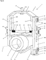
- Fig. 5 shows the upper part of a preferably configured pipe clamp 1 with a mounting part 2, the straight head piece 21 of which is provided with a keyhole opening 210 into which the head of the mounting screw 91 can be hung.
- the keyhole opening 210 has a receiving hole 2100 with a larger diameter and an adjoining holding slot 2101 with a smaller diameter.
- Holding elements 2102 are provided between the receiving hole 2100 and the holding slot 2101.
- the mounting screw 91 pre-mounted on the ceiling can be passed through the receiving hole 2100 and inserted with the screw shaft into the holding slot 2101 at the side. During this process, the screw head is guided over the holding elements 2102, which subsequently prevent the screw head from being able to move back to the receiving hole 2100.
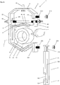
- Figure 6a shows a preferably configured locking part 4, which, for example, to the in Fig. 5
- the part of the assembly part 2 shown connects and has a threaded rod 45 which is rotatably held by the assembly part 2.
- the interfaces shown therefore preferably correspond to one another.
- the first end piece 31 of the closure part 3 is preferably rotatably connected to the threaded rod 45.
- the first end piece 31 is from the Pierce the threaded rod 45 and hold it between the first coupling part 211 and the rotating part 490 connected to the threaded rod 45.
- the second end piece 32 of the closure part 3 can have the configuration from Fig. 2a or Fig.
- the threaded rod 45 replaces the threaded bolt 212 from Figure 2b and is preferably arranged at this height and held on the one hand by the side piece 22 and by the first coupling part 211.
- the second end piece 32 of the closure part 3 is no longer hung on the threaded bolt 212, but on the threaded rod 45 '.
- the first coupling part 211 can again have a hook on which the closure part 3 can be hung. This hook is preferably formed in one piece on the first coupling part 211 or cut out therefrom.
- the mounting part 2 and the closure part 3 connected to it therefore also in this embodiment again form a self-contained frame via which the forces of the acting load can be transmitted.
- the threaded rod 45 has rod ends 451, 452 with opposing threads.
- the nuts 411 which are firmly connected to the end parts 41 of the hold-down device, therefore run against one another or apart when the threaded rod 45 is rotated.
- the screw nuts 411 can be integrated into the end parts 41 of the hold-down device or can be connected to them in a form-fitting manner.
- holding elements or flange elements can be provided on the end parts 41, which hold the nuts 411 in a form-fitting manner.
- the hold-down device 42 is preferably a resilient sheet metal which is optionally pretensioned. z.in Figure 6a the hold-down device 42 is therefore shown in a relaxed or tensioned position. When the threaded rod 45 is rotated, the hold-down device 42 is therefore preferably displaced or deformed into the position shown in FIG Figure 6b shown tense or relaxed position.
- Figure 6b shows the locking part 4 with the downwardly deformed hold-down device 42 from Figure 6a , the end parts 41 of which have been displaced against one another by means of the threaded rod 45.
- the threaded rod 45 is rotated manually by actuating rotating parts 490 which are firmly connected to the threaded rod 45.
- the rotating parts 490 can be in the form of wing nuts or knurled nuts, or the like.
- the locking part 4 is held firmly in this embodiment at, while the hold-down device 42 is deformable for fixing an installed pipe 8.
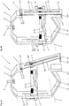
- Figure 7a shows a pipe clamp 1 according to the invention in a further preferred embodiment with a hold-down device 42, which can be optionally inserted into a slot opening 220 on the side piece 22 of the mounting part 2, and can be locked, preferably latched, in a suitable position on the closure part 3.
- the hold-down device 42 and / or the closure part 3 is designed to be elastic.
- the hold-down 42 and / or the closure part 3 is designed as a resilient plate.
- the closure part 3 which can be rotated about a bolt 212 and can preferably be fixed by a wing nut 213, is turned upwards so that a tube 8 can be inserted into the C-shaped assembly part 2.
- the connection between the closure part 3 and the assembly part 2 can also be realized by a rivet.
- the locking part 4 essentially comprises a plate-shaped hold-down device 42, which can be inserted with a first end part 411 into one of several slot openings 220 in the side piece 22 of the assembly part 2.
- a row of latching elements 339 is preferably cut out and bent out of the closure part 3, on which the second end part 412 of the plate-shaped and flexurally elastic hold-down device 42 can be latched.
- the row of locking elements 331 preferably has a sawtooth-shaped course, over which the second end part 412 of the hold-down device 42 is guided until it engages between two saw teeth. So that the shift over the ramps of the sawtooth profile is possible, the hold-down device 42 and / or the closure part 3 is designed to be resilient. After locking up to the hold-down device 42, this is therefore held in a resilient manner.
- Figure 7b shows the pipe clamp 1 of Figure 7a after the tube 8 has been inserted and the closure part 3 has been closed.
- the second end piece 32 of the closure part 3 is provided with a connecting element 320 which can at least partially enclose the foot piece 23 or the second coupling part 231 provided on it or, if necessary, engage it .
- the coupling part 231 is received by a receiving slot 23. The coupling, connecting or locking of the end piece 32 to the coupling part 231 preferably takes place automatically when the closure part 3 is rotated downward into the end position.
- Figure 7c shows the pipe clamp 1 of Figure 7b when fixing the tube 8 by means of the preferably elastic hold-down device 42. Due to the With a small raw diameter, the first end part 411 of the hold-down device 42 is positioned relatively far down in the row of the slot opening 220 on the side piece 22. The first end part 411 preferably has a tongue which is guided through one of the slot openings 220 and is preferably slightly bent so that it is held automatically. The second end part 412 of the hold-down device 42 is guided manually over the latching elements 339 until the tube 8 is fixed and the second end part 412 is held on one of the connecting elements or latching elements 339.
- the end part 412 is preferably bent upwards in the shape of a hook, so that it can engage in one of the connecting elements or latching elements 339 which are bent downwards.
Landscapes
- Engineering & Computer Science (AREA)
- General Engineering & Computer Science (AREA)
- Mechanical Engineering (AREA)
- Architecture (AREA)
- Civil Engineering (AREA)
- Structural Engineering (AREA)
- Supports For Pipes And Cables (AREA)
- Clamps And Clips (AREA)
Applications Claiming Priority (1)
| Application Number | Priority Date | Filing Date | Title |
|---|---|---|---|
| EP19159646 | 2019-02-27 |
Publications (1)
| Publication Number | Publication Date |
|---|---|
| EP3702652A1 true EP3702652A1 (fr) | 2020-09-02 |
Family
ID=65628635
Family Applications (1)
| Application Number | Title | Priority Date | Filing Date |
|---|---|---|---|
| EP19184032.1A Withdrawn EP3702652A1 (fr) | 2019-02-27 | 2019-07-02 | Collier |
Country Status (1)
| Country | Link |
|---|---|
| EP (1) | EP3702652A1 (fr) |
Cited By (3)
| Publication number | Priority date | Publication date | Assignee | Title |
|---|---|---|---|---|
| US11333181B2 (en) * | 2020-07-09 | 2022-05-17 | ASC Engineered Solutions, LLC | Stiffening system for hanger assembly |
| CN115218041A (zh) * | 2021-04-15 | 2022-10-21 | 西安易筑机电工业化科技有限公司 | 一种重型防晃弹簧减震支吊架 |
| US20230268726A1 (en) * | 2022-02-22 | 2023-08-24 | Ford Global Technologies, Llc | Wiring clip for vehicle electronics |
Citations (3)
| Publication number | Priority date | Publication date | Assignee | Title |
|---|---|---|---|---|
| EP2112413A1 (fr) * | 2008-04-25 | 2009-10-28 | Zurecon AG | Collier de serrage pour tuyaux |
| EP2322830A1 (fr) * | 2009-11-13 | 2011-05-18 | Zurecon Ag | Collier multifonctions |
| EP2325539A1 (fr) | 2009-11-13 | 2011-05-25 | Zurecon AG | Collier multifonctions |
-
2019
- 2019-07-02 EP EP19184032.1A patent/EP3702652A1/fr not_active Withdrawn
Patent Citations (3)
| Publication number | Priority date | Publication date | Assignee | Title |
|---|---|---|---|---|
| EP2112413A1 (fr) * | 2008-04-25 | 2009-10-28 | Zurecon AG | Collier de serrage pour tuyaux |
| EP2322830A1 (fr) * | 2009-11-13 | 2011-05-18 | Zurecon Ag | Collier multifonctions |
| EP2325539A1 (fr) | 2009-11-13 | 2011-05-25 | Zurecon AG | Collier multifonctions |
Cited By (4)
| Publication number | Priority date | Publication date | Assignee | Title |
|---|---|---|---|---|
| US11333181B2 (en) * | 2020-07-09 | 2022-05-17 | ASC Engineered Solutions, LLC | Stiffening system for hanger assembly |
| CN115218041A (zh) * | 2021-04-15 | 2022-10-21 | 西安易筑机电工业化科技有限公司 | 一种重型防晃弹簧减震支吊架 |
| US20230268726A1 (en) * | 2022-02-22 | 2023-08-24 | Ford Global Technologies, Llc | Wiring clip for vehicle electronics |
| US11881696B2 (en) * | 2022-02-22 | 2024-01-23 | Ford Global Technologies, Llc | Wiring clip for vehicle electronics |
Similar Documents
| Publication | Publication Date | Title |
|---|---|---|
| DE60037585T2 (de) | Montagesystem und rückhalteclip | |
| EP1283969B1 (fr) | Console | |
| EP2166265A2 (fr) | Collier doté d'une fermeture améliorée | |
| EP3702652A1 (fr) | Collier | |
| EP2587105A1 (fr) | Collier | |
| EP3865749B1 (fr) | Collier de serrage | |
| EP3664236B1 (fr) | Console et système de supportage doté d'une console | |
| EP3401452B1 (fr) | Dispositif de montage pour un objet sanitaire | |
| DE102009042686B3 (de) | Markise | |
| EP3561353B1 (fr) | Dispositif de serrage | |
| DE3823000A1 (de) | Befestigungselement | |
| EP0744503A2 (fr) | Dispositif de fixation, notamment des appareils sanitaires | |
| DE19516145C1 (de) | Rohrschelle, insbesondere für Regenfallrohre | |
| DE19835320A1 (de) | Rohrschelle | |
| EP1120514A2 (fr) | Elément de fixation pour la fixation à distance de lattes, profilés, panneaux ou similaires sur un support fixe | |
| DE102005053650B3 (de) | Scharnierbeschlag | |
| EP0388663B1 (fr) | Collier pour tuyaux | |
| DE202010001441U1 (de) | Justiersystem für Bauelemente | |
| DE102019132327B3 (de) | Türbandanordnung | |
| DE19605541C2 (de) | Rückwandriegel für Möbel wie Schränke oder dergleichen | |
| EP0979905A1 (fr) | Dispositif de connection de deux profilés allongés | |
| EP0269004B1 (fr) | Dispositif pour la fixation d'un échelon à une paroi courbe | |
| EP1637749B1 (fr) | Dispositif de fixation avec vis | |
| DE19540403A1 (de) | Klemmlasche zur Befestigung von Schneefangrohren auf Blechdächern, vorzugsweise für Profilbahnendächer | |
| DE102007031743A1 (de) | Rohrschelle mit verschiebbar befestigtem Schellenkörper |
Legal Events
| Date | Code | Title | Description |
|---|---|---|---|
| PUAI | Public reference made under article 153(3) epc to a published international application that has entered the european phase |
Free format text: ORIGINAL CODE: 0009012 |
|
| STAA | Information on the status of an ep patent application or granted ep patent |
Free format text: STATUS: THE APPLICATION HAS BEEN PUBLISHED |
|
| AK | Designated contracting states |
Kind code of ref document: A1 Designated state(s): AL AT BE BG CH CY CZ DE DK EE ES FI FR GB GR HR HU IE IS IT LI LT LU LV MC MK MT NL NO PL PT RO RS SE SI SK SM TR |
|
| AX | Request for extension of the european patent |
Extension state: BA ME |
|
| STAA | Information on the status of an ep patent application or granted ep patent |
Free format text: STATUS: REQUEST FOR EXAMINATION WAS MADE |
|
| 17P | Request for examination filed |
Effective date: 20210302 |
|
| RBV | Designated contracting states (corrected) |
Designated state(s): AL AT BE BG CH CY CZ DE DK EE ES FI FR GB GR HR HU IE IS IT LI LT LU LV MC MK MT NL NO PL PT RO RS SE SI SK SM TR |
|
| STAA | Information on the status of an ep patent application or granted ep patent |
Free format text: STATUS: THE APPLICATION IS DEEMED TO BE WITHDRAWN |
|
| 18D | Application deemed to be withdrawn |
Effective date: 20210303 |