EP1962317B1 - Appareil de commutation électromagnétique - Google Patents
Appareil de commutation électromagnétique Download PDFInfo
- Publication number
- EP1962317B1 EP1962317B1 EP07003814A EP07003814A EP1962317B1 EP 1962317 B1 EP1962317 B1 EP 1962317B1 EP 07003814 A EP07003814 A EP 07003814A EP 07003814 A EP07003814 A EP 07003814A EP 1962317 B1 EP1962317 B1 EP 1962317B1
- Authority
- EP
- European Patent Office
- Prior art keywords
- armature
- magnet
- switching device
- force
- permanent magnet
- Prior art date
- Legal status (The legal status is an assumption and is not a legal conclusion. Google has not performed a legal analysis and makes no representation as to the accuracy of the status listed.)
- Not-in-force
Links
- 238000010586 diagram Methods 0.000 description 5
- 230000007423 decrease Effects 0.000 description 4
- 238000000418 atomic force spectrum Methods 0.000 description 3
- 230000003247 decreasing effect Effects 0.000 description 2
- 238000000034 method Methods 0.000 description 2
- 241001295925 Gegenes Species 0.000 description 1
- 230000001133 acceleration Effects 0.000 description 1
- 230000006835 compression Effects 0.000 description 1
- 238000007906 compression Methods 0.000 description 1
- 230000008602 contraction Effects 0.000 description 1
- 230000001419 dependent effect Effects 0.000 description 1
- 230000000694 effects Effects 0.000 description 1
- 230000005284 excitation Effects 0.000 description 1
- 230000004907 flux Effects 0.000 description 1
- 230000002401 inhibitory effect Effects 0.000 description 1
- 239000000696 magnetic material Substances 0.000 description 1
Images

Classifications
-
- H—ELECTRICITY
- H01—ELECTRIC ELEMENTS
- H01H—ELECTRIC SWITCHES; RELAYS; SELECTORS; EMERGENCY PROTECTIVE DEVICES
- H01H51/00—Electromagnetic relays
- H01H51/02—Non-polarised relays
- H01H51/04—Non-polarised relays with single armature; with single set of ganged armatures
- H01H51/06—Armature is movable between two limit positions of rest and is moved in one direction due to energisation of an electromagnet and after the electromagnet is de-energised is returned by energy stored during the movement in the first direction, e.g. by using a spring, by using a permanent magnet, by gravity
Definitions
- the invention relates to an electromagnetic switching device with an electromagnet and a movable armature, which is mounted in the switching device with a force acting against the closing force and different in an open position of zero holding force.
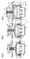
- FIG. 1 contains such a switching device, an electromagnet 1 with a magnetic yoke 2, on the example, two magnetic coils 4 are arranged for magnetic excitation.
- An armature 6 associated with the magnetic yoke 2 is resiliently mounted in a housing 10 of the switching device which is illustrated only symbolically by a return arrangement constructed from two return springs 8 connected in parallel.
- Magnetic yoke 2, solenoid 4 and armature 6 form an electromagnetic drive of the switching device.
- the armature 6 is non-positively connected via a prestressed contact spring 12 with a movable contact bridge 14.
- the movable contact bridge 14 are associated with two fixed contact carrier 16.
- the magnet armature 6 forms the actuator of the magnetic drive for the relative movement between the contact bridge 14 and the contact carrier sixteenth
- the contact bridge 14 and the fixed contact carrier 16 are each provided with contact pieces or contacts 18.
- the switching contact formed by the movable contact bridge 14 and the fixed contact carrier 16 is in the open position (OPEN position).
- the return springs 8 are biased so that the armature 6 is pressed in the rest position of the OPEN position with a biasing or holding force F 0 against a stop 22.
- FIG. 2 now shows a situation in which the contacts 18 touch the first time, the armature 6 has thus covered a distance s 0 .
- the further closing movement of the armature 6 is now carried out against the force exerted by the return springs 8 increasing spring forces and in addition against the action of the force exerted by the parallel contact spring 12, also increasing spring force. Since the spring force exerted by the preloaded contact spring 12 is significantly greater than the spring force exerted by the return spring 8, the total restoring force acting on the armature 6 increases abruptly.
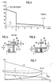
- the associated force curve is in FIG. 4 applied.
- the force exerted on the armature 6 by the return springs 8 and the contact spring 12 restoring force F against the distance d between the pole faces 60, 20 of the armature 6 and the magnetic yoke 2 is applied.
- the curve shows that the return springs 8 (FIG. FIG. 1 ) in the OPEN position the Holding force F 0 exercise. If current flows through the magnetic coils 4, the armature 6 moves under the action of the force exerted by the electromagnet 1 attraction and against the action of the return springs 8 toward the pole faces 20 of the magnetic yoke 2.
- the holding force F 0 exerted on the magnet armature 6 in the OPEN position secures the switching device in this position against accidental closing in the case of external mechanical vibration or impact load. Accordingly, during the entire distance traveled between d 0 and d S , the magnet armature 6 must always overcome the restoring force F exerted by the return springs 8, starting from a finite value required for mechanical securing of the magnet armature 6 in the OPEN position (holding force F 0 ) increases successively. In order nevertheless to achieve short switching times (high closing forces), it is therefore necessary to design and dimension the magnet system 2, 4, 6 such that the magnetic force acting on the magnet armature 6 is significantly higher than the restoring force exerted by the return springs 8. A disadvantage is the constant increase in the restoring forces over the entire working range (magnetic lifting). This results in relatively large, unneeded forces that must be overcome by a correspondingly powerful designed magnetic drive.
- the invention is therefore based on the object to provide an electromagnetic switching device with a magnetic armature, wherein the armature in an OPEN position with the electromagnet switched off by high holding forces on the one hand is securely fixed and on the other hand, the necessary for accelerating the magnet armature magnetic force is significantly reduced.
- the electromagnetic switching device includes an electromagnet and a movable armature which acts in the switching device with a force acting against the closing force and in an OPEN position of zero a different holding force is mounted, which is formed at least in part by a stationary in the switching device outside of the magnetic and magnet armature formed magnetic circuit arranged magnetic arrangement with a permanent magnet which exerts on the armature a dependent of the location of the armature restoring force, which in the OPEN- Position is maximum.
- the return spring can be designed with a smaller spring constant such that it has only a small holding force in the OPEN position.
- OPEN position generally refers to an operating situation of the switching device in which the electromagnet is de-energized and does not exert any magnetic force on the magnet armature.
- the invention is based on the consideration that the restoring force exerted on a movable magnet armature by a stationary permanent magnet in the switching device decreases with increasing distance between magnet armature and permanent magnet, so that on the one hand high holding forces are achieved in the OPEN position, and on the other hand with increasing distance of the magnet armature from the permanent magnet remove the restoring forces inhibiting its movement, so that high accelerations of the armature can be achieved even with smaller forces exerted by the magnetic drive forces.
- An electromagnetic switching device in which the holding force exerted on the magnet armature in the OPEN position is supported by a permanent magnet is basically already known from DE 196 08 729 C1 known.
- There two plate-shaped permanent magnets between an inner and outer yoke of an electromagnet are arranged. In the OPEN position, the magnet armature abuts with its armature plate on the outer yoke.
- Anchor plate, outer yoke, permanent magnet inner yoke and plunger core of the armature form in this way a closed magnetic circuit. Since the permanent magnet is disposed between the outer and inner yoke of the electromagnet, the known switching device can only be operated with direct current or with pulsed direct current. In addition, under certain circumstances, a current control is necessary, which limits the electrical holding power.
- the magnetic circuit must have a two-part yoke.
- the magnet assembly is disposed outside the magnetic circuit formed of electromagnet and armature, that does not affect this, the electromagnet can be energized both with direct current and with alternating current. By increasing the inductance in the closed state also results in a reduced alternating current automatically.
- An electromagnetic switching device in which the magnet armature is held by a permanent magnet in rest position, is out of GB 765 256 A known.
- the return assembly is in the example by return springs 8, of which in the FIG only one is shown (holding force F 10 ), as well as by at least one permanent magnet 32 containing magnet assembly formed on the armature 6 a magnetic force (holding force F 20 ) exerts.
- the permanent magnet 32 is arranged in the direction of movement 33 of the closing movement of the armature 6 seen before this and its pole axis 34 extends parallel to the direction of movement 33.
- the magnet arrangement with the permanent magnet 32 is arranged outside a magnetic circuit 38 formed by the electromagnet 1 and the magnet armature 6 and shown dashed in the FIG so that it does not influence it.
- the resulting at d H holding force F 0 composed of the holding force F 10 of the return spring and the holding force F 20 of the permanent magnet in the OPEN position.
- Curve a shows the course of the restoring force F 1 exerted by the return spring (s ) , which is analogous to that in FIG FIG. 4 shown force profile with decreasing distance d increases linearly.
- Curve b illustrates the course of the restoring force F 2 exerted on the magnet armature by the permanent magnet as a function of the distance d of the magnet armature from the magnet yoke of the electromagnet.
- the permanent magnet 32 may still be provided with an additional baffle 40 on its pole face facing away from the magnet armature 6. This reduces the air path of the field lines and the holding force of the permanent magnet is amplified.
- FIG. 6 Alternatively to the in FIG. 5,6 and 8th illustrated embodiment according to the Polachse 34 of the permanent magnet in the direction of the force exerted by him parallel to the direction of movement 33 of the closing movement of the armature 6 - when the back of the armature 34 is flat, perpendicular to this back - directed, can also according to FIG. 6 a magnet arrangement may be provided, in which the pole axis 34 of the permanent magnet 32 is oriented perpendicular to this direction of movement 33 magnet armature 6.
- lateral guide plates 42 may be arranged. With the help of the dimensions of the baffles 42 also useful and leakage fluxes can be controlled.
- FIG. 9 In addition, a situation is shown in which the magnet armature 6 rests in the open position on the baffles.
- return springs 8 compression springs are shown in the embodiments. In principle, it is also possible to use for the return springs 8 in another arrangement in the switching device tension springs.
Landscapes
- Physics & Mathematics (AREA)
- Electromagnetism (AREA)
- Electromagnets (AREA)
- Driving Mechanisms And Operating Circuits Of Arc-Extinguishing High-Tension Switches (AREA)
- Electronic Switches (AREA)
- Vehicle Body Suspensions (AREA)
Claims (3)
- Appareil de commutation électromagnétique comprenant un électroaimant (1) et une armature magnétique (6) mobile, lequel est logé dans l'appareil de commutation avec une force de retenue (F0) agissant à l'encontre de la force de fermeture et différente de zéro en position OUVERTE et qui est formée, au moins en partie, par un agencement d'aimants comprenant au moins un aimant permanent (32) et disposé de manière fixe dans l'appareil de commutation, en dehors du circuit magnétique (38) formé par l'électroaimant (1) et l'armature magnétique (6), et dont la force de rappel (F2) agissant sur l'armature magnétique (6) est maximale en position OUVERTE, caractérisé en ce l'appareil de commutation est pourvu d'au moins un ressort de rappel (8) agissant parallèlement à la force de rappel exercé par ledit au moins un aimant permanent.
- Appareil de commutation électromagnétique selon la revendication 1, dans lequel ledit au moins un aimant permanent (32) est disposé sur la face arrière, opposée à l'électroaimant (1), de l'armature magnétique (6).
- Appareil de commutation électromagnétique selon la revendication 2, dans lequel ledit au moins un aimant permanent (32) est disposé avec son axe polaire (34) perpendiculairement au sens de déplacement (33) de l'armature magnétique (6), entre deux tôles de guidage (42) s'étendant perpendiculairement à l'axe polaire (34).
Priority Applications (5)
| Application Number | Priority Date | Filing Date | Title |
|---|---|---|---|
| EP07003814A EP1962317B1 (fr) | 2007-02-23 | 2007-02-23 | Appareil de commutation électromagnétique |
| DE502007000936T DE502007000936D1 (de) | 2007-02-23 | 2007-02-23 | Elektromagnetisches Schaltgerät |
| AT07003814T ATE434827T1 (de) | 2007-02-23 | 2007-02-23 | Elektromagnetisches schaltgerät |
| CN2007101954799A CN101252058B (zh) | 2007-02-23 | 2007-11-30 | 电磁开关装置 |
| US12/003,141 US7733202B2 (en) | 2007-02-23 | 2007-12-20 | Electromagnetic switching device |
Applications Claiming Priority (1)
| Application Number | Priority Date | Filing Date | Title |
|---|---|---|---|
| EP07003814A EP1962317B1 (fr) | 2007-02-23 | 2007-02-23 | Appareil de commutation électromagnétique |
Publications (2)
| Publication Number | Publication Date |
|---|---|
| EP1962317A1 EP1962317A1 (fr) | 2008-08-27 |
| EP1962317B1 true EP1962317B1 (fr) | 2009-06-24 |
Family
ID=38245755
Family Applications (1)
| Application Number | Title | Priority Date | Filing Date |
|---|---|---|---|
| EP07003814A Not-in-force EP1962317B1 (fr) | 2007-02-23 | 2007-02-23 | Appareil de commutation électromagnétique |
Country Status (5)
| Country | Link |
|---|---|
| US (1) | US7733202B2 (fr) |
| EP (1) | EP1962317B1 (fr) |
| CN (1) | CN101252058B (fr) |
| AT (1) | ATE434827T1 (fr) |
| DE (1) | DE502007000936D1 (fr) |
Families Citing this family (4)
| Publication number | Priority date | Publication date | Assignee | Title |
|---|---|---|---|---|
| CN201774463U (zh) * | 2010-06-14 | 2011-03-23 | 鸿富锦精密工业(深圳)有限公司 | 节能适配器 |
| DE102011052003B4 (de) | 2011-07-20 | 2022-06-15 | Te Connectivity Germany Gmbh | Schaltvorrichtung mit Überlastsicherungsvorrichtung und einem ersten und einem zweiten Betätigungsorgan |
| US9281147B2 (en) * | 2013-12-30 | 2016-03-08 | Elbex Video Ltd. | Mechanical latching relays and method for operating the relays |
| JP6814184B2 (ja) * | 2018-09-19 | 2021-01-13 | 株式会社Subaru | 電気自動車 |
Family Cites Families (15)
| Publication number | Priority date | Publication date | Assignee | Title |
|---|---|---|---|---|
| DE358530C (de) * | 1922-09-12 | Siemens & Halske Akt Ges | Pruefanordnung fuer Doppelpruefen in Fernsprechanlagen mit Waehlerbetrieb | |
| US1606164A (en) * | 1923-05-09 | 1926-11-09 | Western Electric Co | Circuit-controlling device |
| US2539547A (en) * | 1945-06-13 | 1951-01-30 | Clare & Co C P | Relay |
| FR1188404A (fr) * | 1954-02-17 | 1959-09-22 | Perfectionnements aux relais et contacteurs bipolaires | |
| US3184563A (en) * | 1960-12-09 | 1965-05-18 | Int Standard Electric Corp | Magnetically controlled reed switching device |
| US3281739A (en) * | 1963-09-16 | 1966-10-25 | Phillips Eckardt Electronic Co | Sensitive latching relay |
| US3274523A (en) * | 1964-03-02 | 1966-09-20 | Allied Control Co | Electromagnetic switching relay having a three piece u-shaped core |
| JPS59218871A (ja) * | 1983-05-27 | 1984-12-10 | Matsushita Electric Works Ltd | ドツトプリンタ用電磁石装置 |
| FR2573570B1 (fr) * | 1984-11-22 | 1988-05-27 | Merlin Gerin | Relais electromagnetique polarise a accrochage magnetique pour un declencheur d'un disjoncteur electrique |
| US4728917A (en) * | 1986-01-16 | 1988-03-01 | Siemens Aktiengesellschaft | Electromagnetic relay wherein response voltage is rendered temperature independent |
| JPH0642420B2 (ja) * | 1988-12-23 | 1994-06-01 | 松下電工株式会社 | 単安定電磁石 |
| US5365210A (en) * | 1993-09-21 | 1994-11-15 | Alliedsignal Inc. | Latching solenoid with manual override |
| DE19608729C1 (de) * | 1996-03-06 | 1997-07-03 | Siemens Ag | Elektromagnetisches Schaltgerät |
| JP4230246B2 (ja) * | 2002-08-27 | 2009-02-25 | 三菱電機株式会社 | 操作装置およびその操作装置を使用した開閉装置 |
| CN2671113Y (zh) * | 2003-12-30 | 2005-01-12 | 吴光 | 双稳态磁保持继电器 |
-
2007
- 2007-02-23 DE DE502007000936T patent/DE502007000936D1/de active Active
- 2007-02-23 AT AT07003814T patent/ATE434827T1/de active
- 2007-02-23 EP EP07003814A patent/EP1962317B1/fr not_active Not-in-force
- 2007-11-30 CN CN2007101954799A patent/CN101252058B/zh not_active Expired - Fee Related
- 2007-12-20 US US12/003,141 patent/US7733202B2/en not_active Expired - Fee Related
Also Published As
| Publication number | Publication date |
|---|---|
| US20090045893A1 (en) | 2009-02-19 |
| CN101252058A (zh) | 2008-08-27 |
| ATE434827T1 (de) | 2009-07-15 |
| CN101252058B (zh) | 2012-05-30 |
| US7733202B2 (en) | 2010-06-08 |
| DE502007000936D1 (de) | 2009-08-06 |
| EP1962317A1 (fr) | 2008-08-27 |
Similar Documents
| Publication | Publication Date | Title |
|---|---|---|
| EP3061104B1 (fr) | Actionneur électromécanique | |
| DE112011104482T5 (de) | Magnetbetätigte Vorrichtung | |
| EP0373142A1 (fr) | Aimant bistable | |
| DE102011078932A1 (de) | Induktionsgenerator | |
| EP2272076B1 (fr) | Dispositif de commutation | |
| DE102013107744A1 (de) | Aktuatorvorrichtung | |
| DE19808492B4 (de) | Elektromagnetischer Aktuator mit wirbelstromarmen Anker und zugehöriges Verfahren | |
| EP1962317B1 (fr) | Appareil de commutation électromagnétique | |
| DE10207828A1 (de) | Elektromagnetischer Hubmagnet mit Permanentmagnet | |
| DE102010002596A1 (de) | Elektromagnetisches Schütz | |
| EP1132929B1 (fr) | Entraînement à aimant permanent pour dispositif de commutation électrique | |
| EP1891654A1 (fr) | Appareil de commutation electromagnetique, et procede pour faire fonctionner un appareil de commutation electromagnetique | |
| EP1417694B1 (fr) | Dispositif a electroaimant pour interrupteur | |
| EP2179430B1 (fr) | Actionneur electromagnetique | |
| DE102018001243B4 (de) | Bistabiler elektromagnetischer Hubaktor sowie Drahtziehmaschine | |
| EP0922893B1 (fr) | Soupape | |
| DE102018216292B4 (de) | Elektromagnetischer Auslöser für elektromagnetische Schaltgeräte mit einem gewinkelten Aufbau | |
| EP1897108B1 (fr) | Dispositif de commutation electrique dote d'elements de reglage magnetiques pour un element de commutation | |
| DE102005039263B4 (de) | Steuervorrichtung und Verfahren zum Ansteuern eines Aktuators für eine Getriebeschaltstelle | |
| EP1962319B1 (fr) | Appareil de commutation électromagnétique | |
| DE19813128A1 (de) | Elektromagnetisches Relais | |
| DE102005051942B3 (de) | Bistabile elektrische Schaltvorrichtung | |
| DE10239284B4 (de) | Elektromagnetisches Relais mit nichtlinearem Kraft-Weg-Verhalten der Kontaktfeder und Kontaktfeder | |
| DE2836705C2 (de) | Auslöse-Elektromagnet | |
| EP2743940B1 (fr) | Actionneur électromagnétique |
Legal Events
| Date | Code | Title | Description |
|---|---|---|---|
| PUAI | Public reference made under article 153(3) epc to a published international application that has entered the european phase |
Free format text: ORIGINAL CODE: 0009012 |
|
| 17P | Request for examination filed |
Effective date: 20071011 |
|
| AK | Designated contracting states |
Kind code of ref document: A1 Designated state(s): AT BE BG CH CY CZ DE DK EE ES FI FR GB GR HU IE IS IT LI LT LU LV MC NL PL PT RO SE SI SK TR |
|
| AX | Request for extension of the european patent |
Extension state: AL BA HR MK RS |
|
| GRAP | Despatch of communication of intention to grant a patent |
Free format text: ORIGINAL CODE: EPIDOSNIGR1 |
|
| AKX | Designation fees paid |
Designated state(s): AT BE BG CH CY CZ DE DK EE ES FI FR GB GR HU IE IS IT LI LT LU LV MC NL PL PT RO SE SI SK TR |
|
| GRAS | Grant fee paid |
Free format text: ORIGINAL CODE: EPIDOSNIGR3 |
|
| GRAL | Information related to payment of fee for publishing/printing deleted |
Free format text: ORIGINAL CODE: EPIDOSDIGR3 |
|
| GRAS | Grant fee paid |
Free format text: ORIGINAL CODE: EPIDOSNIGR3 |
|
| GRAA | (expected) grant |
Free format text: ORIGINAL CODE: 0009210 |
|
| AK | Designated contracting states |
Kind code of ref document: B1 Designated state(s): AT BE BG CH CY CZ DE DK EE ES FI FR GB GR HU IE IS IT LI LT LU LV MC NL PL PT RO SE SI SK TR |
|
| REG | Reference to a national code |
Ref country code: GB Ref legal event code: FG4D Free format text: NOT ENGLISH |
|
| REG | Reference to a national code |
Ref country code: CH Ref legal event code: EP |
|
| REG | Reference to a national code |
Ref country code: IE Ref legal event code: FG4D Free format text: LANGUAGE OF EP DOCUMENT: GERMAN |
|
| REF | Corresponds to: |
Ref document number: 502007000936 Country of ref document: DE Date of ref document: 20090806 Kind code of ref document: P |
|
| PG25 | Lapsed in a contracting state [announced via postgrant information from national office to epo] |
Ref country code: FI Free format text: LAPSE BECAUSE OF FAILURE TO SUBMIT A TRANSLATION OF THE DESCRIPTION OR TO PAY THE FEE WITHIN THE PRESCRIBED TIME-LIMIT Effective date: 20090624 Ref country code: LT Free format text: LAPSE BECAUSE OF FAILURE TO SUBMIT A TRANSLATION OF THE DESCRIPTION OR TO PAY THE FEE WITHIN THE PRESCRIBED TIME-LIMIT Effective date: 20090624 |
|
| PG25 | Lapsed in a contracting state [announced via postgrant information from national office to epo] |
Ref country code: SE Free format text: LAPSE BECAUSE OF FAILURE TO SUBMIT A TRANSLATION OF THE DESCRIPTION OR TO PAY THE FEE WITHIN THE PRESCRIBED TIME-LIMIT Effective date: 20090924 Ref country code: SI Free format text: LAPSE BECAUSE OF FAILURE TO SUBMIT A TRANSLATION OF THE DESCRIPTION OR TO PAY THE FEE WITHIN THE PRESCRIBED TIME-LIMIT Effective date: 20090624 Ref country code: LV Free format text: LAPSE BECAUSE OF FAILURE TO SUBMIT A TRANSLATION OF THE DESCRIPTION OR TO PAY THE FEE WITHIN THE PRESCRIBED TIME-LIMIT Effective date: 20090624 Ref country code: PL Free format text: LAPSE BECAUSE OF FAILURE TO SUBMIT A TRANSLATION OF THE DESCRIPTION OR TO PAY THE FEE WITHIN THE PRESCRIBED TIME-LIMIT Effective date: 20090624 |
|
| NLV1 | Nl: lapsed or annulled due to failure to fulfill the requirements of art. 29p and 29m of the patents act | ||
| PG25 | Lapsed in a contracting state [announced via postgrant information from national office to epo] |
Ref country code: ES Free format text: LAPSE BECAUSE OF FAILURE TO SUBMIT A TRANSLATION OF THE DESCRIPTION OR TO PAY THE FEE WITHIN THE PRESCRIBED TIME-LIMIT Effective date: 20091005 Ref country code: CZ Free format text: LAPSE BECAUSE OF FAILURE TO SUBMIT A TRANSLATION OF THE DESCRIPTION OR TO PAY THE FEE WITHIN THE PRESCRIBED TIME-LIMIT Effective date: 20090624 Ref country code: EE Free format text: LAPSE BECAUSE OF FAILURE TO SUBMIT A TRANSLATION OF THE DESCRIPTION OR TO PAY THE FEE WITHIN THE PRESCRIBED TIME-LIMIT Effective date: 20090624 Ref country code: IS Free format text: LAPSE BECAUSE OF FAILURE TO SUBMIT A TRANSLATION OF THE DESCRIPTION OR TO PAY THE FEE WITHIN THE PRESCRIBED TIME-LIMIT Effective date: 20091024 |
|
| REG | Reference to a national code |
Ref country code: IE Ref legal event code: FD4D |
|
| PG25 | Lapsed in a contracting state [announced via postgrant information from national office to epo] |
Ref country code: SK Free format text: LAPSE BECAUSE OF FAILURE TO SUBMIT A TRANSLATION OF THE DESCRIPTION OR TO PAY THE FEE WITHIN THE PRESCRIBED TIME-LIMIT Effective date: 20090624 Ref country code: NL Free format text: LAPSE BECAUSE OF FAILURE TO SUBMIT A TRANSLATION OF THE DESCRIPTION OR TO PAY THE FEE WITHIN THE PRESCRIBED TIME-LIMIT Effective date: 20090624 |
|
| PG25 | Lapsed in a contracting state [announced via postgrant information from national office to epo] |
Ref country code: PT Free format text: LAPSE BECAUSE OF FAILURE TO SUBMIT A TRANSLATION OF THE DESCRIPTION OR TO PAY THE FEE WITHIN THE PRESCRIBED TIME-LIMIT Effective date: 20091024 Ref country code: BG Free format text: LAPSE BECAUSE OF FAILURE TO SUBMIT A TRANSLATION OF THE DESCRIPTION OR TO PAY THE FEE WITHIN THE PRESCRIBED TIME-LIMIT Effective date: 20090924 |
|
| PG25 | Lapsed in a contracting state [announced via postgrant information from national office to epo] |
Ref country code: DK Free format text: LAPSE BECAUSE OF FAILURE TO SUBMIT A TRANSLATION OF THE DESCRIPTION OR TO PAY THE FEE WITHIN THE PRESCRIBED TIME-LIMIT Effective date: 20090624 Ref country code: IE Free format text: LAPSE BECAUSE OF FAILURE TO SUBMIT A TRANSLATION OF THE DESCRIPTION OR TO PAY THE FEE WITHIN THE PRESCRIBED TIME-LIMIT Effective date: 20090624 |
|
| PLBE | No opposition filed within time limit |
Free format text: ORIGINAL CODE: 0009261 |
|
| STAA | Information on the status of an ep patent application or granted ep patent |
Free format text: STATUS: NO OPPOSITION FILED WITHIN TIME LIMIT |
|
| 26N | No opposition filed |
Effective date: 20100325 |
|
| BERE | Be: lapsed |
Owner name: SIEMENS A.G. Effective date: 20100228 |
|
| PG25 | Lapsed in a contracting state [announced via postgrant information from national office to epo] |
Ref country code: GR Free format text: LAPSE BECAUSE OF FAILURE TO SUBMIT A TRANSLATION OF THE DESCRIPTION OR TO PAY THE FEE WITHIN THE PRESCRIBED TIME-LIMIT Effective date: 20090925 Ref country code: MC Free format text: LAPSE BECAUSE OF NON-PAYMENT OF DUE FEES Effective date: 20100301 |
|
| PG25 | Lapsed in a contracting state [announced via postgrant information from national office to epo] |
Ref country code: BE Free format text: LAPSE BECAUSE OF NON-PAYMENT OF DUE FEES Effective date: 20100228 |
|
| PGRI | Patent reinstated in contracting state [announced from national office to epo] |
Ref country code: IT Effective date: 20110501 |
|
| REG | Reference to a national code |
Ref country code: CH Ref legal event code: PL |
|
| GBPC | Gb: european patent ceased through non-payment of renewal fee |
Effective date: 20110223 |
|
| PG25 | Lapsed in a contracting state [announced via postgrant information from national office to epo] |
Ref country code: LI Free format text: LAPSE BECAUSE OF NON-PAYMENT OF DUE FEES Effective date: 20110228 Ref country code: CH Free format text: LAPSE BECAUSE OF NON-PAYMENT OF DUE FEES Effective date: 20110228 |
|
| PG25 | Lapsed in a contracting state [announced via postgrant information from national office to epo] |
Ref country code: GB Free format text: LAPSE BECAUSE OF NON-PAYMENT OF DUE FEES Effective date: 20110223 |
|
| PG25 | Lapsed in a contracting state [announced via postgrant information from national office to epo] |
Ref country code: CY Free format text: LAPSE BECAUSE OF FAILURE TO SUBMIT A TRANSLATION OF THE DESCRIPTION OR TO PAY THE FEE WITHIN THE PRESCRIBED TIME-LIMIT Effective date: 20090624 |
|
| PG25 | Lapsed in a contracting state [announced via postgrant information from national office to epo] |
Ref country code: HU Free format text: LAPSE BECAUSE OF FAILURE TO SUBMIT A TRANSLATION OF THE DESCRIPTION OR TO PAY THE FEE WITHIN THE PRESCRIBED TIME-LIMIT Effective date: 20091225 Ref country code: LU Free format text: LAPSE BECAUSE OF NON-PAYMENT OF DUE FEES Effective date: 20100223 |
|
| PG25 | Lapsed in a contracting state [announced via postgrant information from national office to epo] |
Ref country code: TR Free format text: LAPSE BECAUSE OF FAILURE TO SUBMIT A TRANSLATION OF THE DESCRIPTION OR TO PAY THE FEE WITHIN THE PRESCRIBED TIME-LIMIT Effective date: 20090624 |
|
| REG | Reference to a national code |
Ref country code: AT Ref legal event code: MM01 Ref document number: 434827 Country of ref document: AT Kind code of ref document: T Effective date: 20120223 |
|
| PG25 | Lapsed in a contracting state [announced via postgrant information from national office to epo] |
Ref country code: AT Free format text: LAPSE BECAUSE OF NON-PAYMENT OF DUE FEES Effective date: 20120223 |
|
| PG25 | Lapsed in a contracting state [announced via postgrant information from national office to epo] |
Ref country code: RO Free format text: LAPSE BECAUSE OF FAILURE TO SUBMIT A TRANSLATION OF THE DESCRIPTION OR TO PAY THE FEE WITHIN THE PRESCRIBED TIME-LIMIT Effective date: 20090624 |
|
| REG | Reference to a national code |
Ref country code: FR Ref legal event code: PLFP Year of fee payment: 10 |
|
| REG | Reference to a national code |
Ref country code: FR Ref legal event code: PLFP Year of fee payment: 11 |
|
| REG | Reference to a national code |
Ref country code: FR Ref legal event code: PLFP Year of fee payment: 12 |
|
| PGFP | Annual fee paid to national office [announced via postgrant information from national office to epo] |
Ref country code: IT Payment date: 20200224 Year of fee payment: 14 |
|
| PGFP | Annual fee paid to national office [announced via postgrant information from national office to epo] |
Ref country code: FR Payment date: 20200211 Year of fee payment: 14 |
|
| PGFP | Annual fee paid to national office [announced via postgrant information from national office to epo] |
Ref country code: DE Payment date: 20200420 Year of fee payment: 14 |
|
| REG | Reference to a national code |
Ref country code: DE Ref legal event code: R119 Ref document number: 502007000936 Country of ref document: DE |
|
| PG25 | Lapsed in a contracting state [announced via postgrant information from national office to epo] |
Ref country code: DE Free format text: LAPSE BECAUSE OF NON-PAYMENT OF DUE FEES Effective date: 20210901 Ref country code: FR Free format text: LAPSE BECAUSE OF NON-PAYMENT OF DUE FEES Effective date: 20210228 |
|
| PG25 | Lapsed in a contracting state [announced via postgrant information from national office to epo] |
Ref country code: IT Free format text: LAPSE BECAUSE OF NON-PAYMENT OF DUE FEES Effective date: 20210228 |