EP3061104B1 - Actionneur électromécanique - Google Patents
Actionneur électromécanique Download PDFInfo
- Publication number
- EP3061104B1 EP3061104B1 EP14820732.7A EP14820732A EP3061104B1 EP 3061104 B1 EP3061104 B1 EP 3061104B1 EP 14820732 A EP14820732 A EP 14820732A EP 3061104 B1 EP3061104 B1 EP 3061104B1
- Authority
- EP
- European Patent Office
- Prior art keywords
- drive
- armature
- magnets
- force
- stroke
- Prior art date
- Legal status (The legal status is an assumption and is not a legal conclusion. Google has not performed a legal analysis and makes no representation as to the accuracy of the status listed.)
- Active
Links
Images
Classifications
-
- H—ELECTRICITY
- H02—GENERATION; CONVERSION OR DISTRIBUTION OF ELECTRIC POWER
- H02K—DYNAMO-ELECTRIC MACHINES
- H02K33/00—Motors with reciprocating, oscillating or vibrating magnet, armature or coil system
- H02K33/02—Motors with reciprocating, oscillating or vibrating magnet, armature or coil system with armatures moved one way by energisation of a single coil system and returned by mechanical force, e.g. by springs
-
- H—ELECTRICITY
- H01—ELECTRIC ELEMENTS
- H01F—MAGNETS; INDUCTANCES; TRANSFORMERS; SELECTION OF MATERIALS FOR THEIR MAGNETIC PROPERTIES
- H01F7/00—Magnets
- H01F7/06—Electromagnets; Actuators including electromagnets
- H01F7/08—Electromagnets; Actuators including electromagnets with armatures
- H01F7/16—Rectilinearly-movable armatures
- H01F7/1638—Armatures not entering the winding
- H01F7/1646—Armatures or stationary parts of magnetic circuit having permanent magnet
-
- E—FIXED CONSTRUCTIONS
- E05—LOCKS; KEYS; WINDOW OR DOOR FITTINGS; SAFES
- E05B—LOCKS; ACCESSORIES THEREFOR; HANDCUFFS
- E05B47/00—Operating or controlling locks or other fastening devices by electric or magnetic means
- E05B47/0001—Operating or controlling locks or other fastening devices by electric or magnetic means with electric actuators; Constructional features thereof
-
- H—ELECTRICITY
- H01—ELECTRIC ELEMENTS
- H01F—MAGNETS; INDUCTANCES; TRANSFORMERS; SELECTION OF MATERIALS FOR THEIR MAGNETIC PROPERTIES
- H01F7/00—Magnets
- H01F7/06—Electromagnets; Actuators including electromagnets
- H01F7/08—Electromagnets; Actuators including electromagnets with armatures
- H01F7/121—Guiding or setting position of armatures, e.g. retaining armatures in their end position
- H01F7/122—Guiding or setting position of armatures, e.g. retaining armatures in their end position by permanent magnets
-
- H—ELECTRICITY
- H01—ELECTRIC ELEMENTS
- H01F—MAGNETS; INDUCTANCES; TRANSFORMERS; SELECTION OF MATERIALS FOR THEIR MAGNETIC PROPERTIES
- H01F7/00—Magnets
- H01F7/06—Electromagnets; Actuators including electromagnets
- H01F7/08—Electromagnets; Actuators including electromagnets with armatures
- H01F7/16—Rectilinearly-movable armatures
- H01F7/1607—Armatures entering the winding
- H01F7/1615—Armatures or stationary parts of magnetic circuit having permanent magnet
-
- H—ELECTRICITY
- H01—ELECTRIC ELEMENTS
- H01H—ELECTRIC SWITCHES; RELAYS; SELECTORS; EMERGENCY PROTECTIVE DEVICES
- H01H50/00—Details of electromagnetic relays
- H01H50/16—Magnetic circuit arrangements
- H01H50/18—Movable parts of magnetic circuits, e.g. armature
- H01H50/20—Movable parts of magnetic circuits, e.g. armature movable inside coil and substantially lengthwise with respect to axis thereof; movable coaxially with respect to coil
-
- H—ELECTRICITY
- H01—ELECTRIC ELEMENTS
- H01H—ELECTRIC SWITCHES; RELAYS; SELECTORS; EMERGENCY PROTECTIVE DEVICES
- H01H51/00—Electromagnetic relays
- H01H51/22—Polarised relays
- H01H51/2209—Polarised relays with rectilinearly movable armature
-
- H—ELECTRICITY
- H01—ELECTRIC ELEMENTS
- H01H—ELECTRIC SWITCHES; RELAYS; SELECTORS; EMERGENCY PROTECTIVE DEVICES
- H01H51/00—Electromagnetic relays
- H01H51/22—Polarised relays
- H01H51/2209—Polarised relays with rectilinearly movable armature
- H01H2051/2218—Polarised relays with rectilinearly movable armature having at least one movable permanent magnet
-
- H—ELECTRICITY
- H01—ELECTRIC ELEMENTS
- H01H—ELECTRIC SWITCHES; RELAYS; SELECTORS; EMERGENCY PROTECTIVE DEVICES
- H01H33/00—High-tension or heavy-current switches with arc-extinguishing or arc-preventing means
- H01H33/60—Switches wherein the means for extinguishing or preventing the arc do not include separate means for obtaining or increasing flow of arc-extinguishing fluid
- H01H33/66—Vacuum switches
- H01H33/666—Operating arrangements
- H01H33/6662—Operating arrangements using bistable electromagnetic actuators, e.g. linear polarised electromagnetic actuators
Definitions
- the present invention relates to the field of electromechanical actuators, for example a reversing solenoid.
- Reversing solenoids are well known and state of the art. For example, bistable designs are used to drive electrical medium-voltage switching devices, with electrolytic capacitors being used to power the magnets. Other fields of application can be found, for example, in solenoid valves, which should be able to hold a state against a restoring force without power. In addition, there are numerous other applications, including in sorting and conveyor systems, but also in the automotive sector (especially gear technology, central locking, shift locks) and in knitting machines. Important possible areas of application are also in the field of so-called hot runner technology (actuating the needles of injection molding tools) and in the field of robotic welding guns (tracking of the welding electrodes, whereby the necessary play compensation can be guaranteed by springs).
- a disadvantage of known reversing solenoids which often precludes their use instead of pneumatic or hydraulic drives (or non-positively locked spring accumulators), is their often low electrical efficiency. In medium-voltage switching devices with (bistable) reversing solenoids, this leads to considerable costs, primarily due to the expensive electrolytic capacitors. In other areas of technology, especially with valves in engines - for example gas valves in large gas engines - the low electrical efficiency leads to an undesirable limitation of the permissible switching frequency or frequency due to the power loss occurring in the coils (the coils would thermally react at higher switching frequencies be destroyed).
- bistable reversing solenoids tend to have the highest armature speed when the armature reaches a stroke end position at the end of an actuating process. This leads to high expenditure for the end position cushioning or limits the service life of the magnet.
- reversing solenoids should be monostable instead of bistable in order to be able to assume a safe end position without power.
- a drive according to the preamble of claim 1 is known from publication GB 2 325 567 A famous.
- the object on which the invention is based is therefore to increase the electrical efficiency of polarized reversing lifting magnets, in particular bistable ones. Furthermore, the new magnets should be able to have high dynamics with reduced dead times compared to known reversing solenoids. In addition, a general requirement for actuators is a compact design.
- the present invention shows a drive that has at least one armature, at least one soft-magnetic frame, at least one coil and at least one permanent magnet, which is attached to the armature or armatures, the frame and armature being designed in such a way that the current generated by the ( The magnetic flux generated by the coil(s) at least partially penetrates the permanent magnet(s), so that a force acts on them and is transmitted to the armature; the arrangement of the armature, frame and permanent magnet(s) is such that the magnetic flux generated by the coil(s) is at least partially inhomogeneous perpendicular to the direction of polarization of the permanent magnet(s) during the lifting movement, which is caused by the coil(s) and The magnetic flux density felt by the permanent magnet(s) has a gradient perpendicular to the direction of polarization of the permanent magnets, with the armature and frame being designed in such a way that the armature(s) together with the permanent magnet(s) attached to it can at least partially dip into the frame; and
- the permanent magnetically polarized reversing solenoid also has a spring system which exerts a force on the armature in both stroke end positions in the direction of movement towards the middle stroke position (ie towards the center between the two stroke end positions).
- the spring system must be designed in such a way that in at least one stroke end position the spring force is smaller than the total reluctance force acting on the armature in the static, de-energized case, so that the armature can be held stable in at least one end position against the spring force by permanent magnets.
- the drives according to the invention should be able to be designed in such a way that, in relation to their volume, they can generate greater forces (than known reversing lifting magnets). Ultimately, the drive should also be able to be designed monostable and still be able to have short positioning times and high efficiencies.
- bistable reversing lifting magnets As a result of spring system, the armature starts to move from each stroke end position in the direction of the middle stroke position as soon as the holding force (the holding force is defined as the total reluctance force on the armature in the respective stroke end position) is smaller than the spring force as a result of an electrical counter-excitation. This requires far less electrical power than conventional bistable reversing solenoids without a spring system, and the associated (external) rate of increase in force can also be far higher.
- A1 and A2 are the (opposite) pole faces of the armature and F stop is a function representing the end position stops.
- the armature can initially be accelerated predominantly with spring force, for which only a relatively low electrical power consumption is required (for counter-excitation).
- Moving or accelerating electrical machines can have much higher electrical efficiencies than those that start from the rest position. This is ultimately due to the fact that the work done by the drive is an integral of the force over the travel, but the heat loss is an integral of the power loss over time. It is therefore clear that a reduction in the actuating time, i.e. a reduction in the integration interval in the time domain, tends to lead to an increase in electrical efficiency. Likewise, it is clear that "stuck" the armature in any position must result in zero efficiency as the work integral vanishes and the integration time escalates.
- One aspect of the example described here is that only a small counter-excitation, which can be generated quickly, is required to trigger the movement.
- a symmetrical spring system could move the armature back and forth between its end positions within a certain oscillation time without having to use any energy at all.
- the spring system must be designed in such a way that the elastically stored (potential) energy is as large as possible in both stroke end positions. With a spring system designed in this way, only the above-mentioned counter-excitation must be generated and enough electrical power supplied to the drive so that it can start moving, overcome the friction and, if necessary, additional useful work can be carried out.
- drives with a spring system usually have to do less work than conventional reversing solenoids in order to move from one stroke end position to the other in a finite amount of time. And as a result of the "pre-acceleration" by the spring system, they can also do this smaller amount of work with greater electrical efficiency. This leads to correspondingly small power losses and enables higher switching frequencies, where these were previously limited by the power loss or (integral) heat loss.
- the drives with a spring system have major advantages over conventional bistable reversing solenoids:
- the dead time of the drives described here is usually shorter, the Actuating time is lower, the efficiency is higher, the end position speed is lower.
- Due to the spring system, the new magnets in a bistable design have at least one latching point in the de-energized case, which does not correspond to a stroke end position.
- the magnets can easily be designed in such a way that the armature is nevertheless transported magnetically against the restoring force of the spring system into the desired stroke end position.
- the magnet When operated on a switchable (constant) voltage source, the magnet can be designed in such a way that it does not come close to reaching its equilibrium current during a regular adjustment process as a result of mutual induction from the coil or coils. If, as a result of the behavior of the mechanical load, for example high friction, the drive is "caught" in the vicinity of its resting point, the current increases and with it, with a certain delay due to self-induction and eddy current effects, the reluctance force acting on the armature, which is always sufficient in the end can tension the spring system again and move the anchor in to move to the desired final position.
- the stationary total force (composed of magnetic and spring force) must be greater than the friction possibly acting on the system; if necessary, the associated steady-state total force characteristic must be matched to the respective application with regard to possible restoring forces (e.g. the pneumatic pressure if the monostable drive is to overcome a pneumatic valve, such as that used in automatic transmissions).
- the reluctance force In the unstable end position in the stationary, de-energized case, the reluctance force must not be limited by magnetic saturation. This means that magnetic saturation should never occur in any area over the entire effective iron cross-section in that magnetic partial circuit which includes the adhesive surface(s) of the armature which is in contact with the stator. In this way, by energizing the coil(s), the reluctance force in the non-energized, unstable end position can be increased to such an extent that the magnet is also (meta-)stable against the spring force in this ("second") end position, as long as the electrical power required for this is expended.
- the magnet should be dimensioned in such a way that the greatest possible increase in the reluctance force in the "unstable" ("second") stroke end position is achieved with the lowest possible electrical power - this is also important in order to keep the magnet in the unstable end position with high duty cycles to be able to
- the spring system it doesn't have to be linear.
- it has a progressive characteristic with respect to the stable end-of-stroke position, that is, the spring force driving the armature system toward the mid-stroke position increases more than linearly as the armature system approaches the stable ("first") end-of-stroke position. This can also be achieved by combining several linear springs.
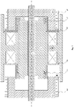
- a (here: rotationally symmetrical) embodiment of a drive according to the invention is shown in 1 shown, the optional spring system is again not shown.
- the magnet in 1 has a stator 11, two armatures 21, 22, two coils 31, 32 and a push rod 71 which rigidly connects the two armatures. (Note: For drives acc. 1 it is generally advantageous to connect the coils 31, 32 in series in the same direction).
- the magnet can behave as a double lifting magnet, consisting of two individual magnets mounted back-to-back, sharing the same drive axis.
- essential for this Embodiment of the invention is the attachment of the permanent magnets on the armature.
- the magnet has additional (radial) "air gaps", without which the armature could not be under (significant) magnetic tension in relation to the stator, as described.
- the armatures are not connected to the stator 11 in a magnetically conductive manner over a large area.
- the radial air gaps in question are filled here, for example, with a plain bearing material 51, 52 (which can also serve as emergency bearings; in the model shown, space is provided for plain bearings on the drive axle).
- These required radial air gaps can be as in 1 be designed to influence the characteristic curve(s) of the drive according to the respective application.
- stage S can be used to generate a particularly high force increase rate in the area of the middle position of the stroke, even when there is no current - this may be necessary, especially in designs without a spring system, to prevent the armature from stopping in an undefined position. Without an additional air gap, no part of the magnet would be able to generate a holding force during longer strokes, since each armature would magnetically short-circuit its permanent magnet if it plunged too deeply into the stator.
- the permanent magnets can be designed, for example, as diametrically or radially polarized segments of a circle.
- a bistable drive can also be obtained with only one of the two magnets mounted quasi back-to-back, i.e. one "drive half", by replacing the other with a spring or spring system to be dimensioned accordingly.
- Such drives also do not have to be rotationally symmetrical.
- Non-rotationally symmetrical variants can also be implemented with a transversal flow path in order to represent particularly long-stroke drives.
- Advantage of drives according to 1 is that when using Permanent magnets with high energy density can have remarkably high force constants with comparatively long strokes.
- the drives are very versatile.
- the combination with a spring system which drives the armature system from each of the two end positions in the direction of the middle position, enables very fast drives with high efficiency, high force constants, therefore high lifting work, and yet low wear, since the armature speed is reduced by the spring system before the end position is reached is significantly reduced.
- a spring system is dispensed with and a metal with good electrical conductivity is used as the "emergency bearing" 51, 52, the emergency bearings also act as eddy current brakes and enable slow armature movements, in which the full stationary force with a given current is only built up as soon as the armature, for example, .being held in place by friction or the load.
- the "eddy current brakes” (designed here as emergency bearings), which can also be attached to the armature or armatures instead of the stator, also dampen bouncing processes.
- the permanent magnets (PM) attached to the armatures also constitute a type of magnetic spring system.
- the magnet For highly dynamic drives with, in particular, mechanical springs, it is advisable to construct rotationally symmetrical designs of the magnet, or at least those with a rotationally symmetrical inner pole, from SMC materials. Machined parts from solid material are better suited to the slower "springless" design (i.e. those without mechanical or pneumatic springs), especially when using the eddy current brakes described.
- the magnetic yoke R enables easy installation of the permanent magnets, which it also serves as a stop, but at the same time has a strong influence on the characteristic curve and, above all, increases the force at the start of the stroke.
- the reversing solenoid has a spring system, which exerts a force on the armature in both stroke end positions in the direction of movement toward the middle position.
- the spring system must be designed in such a way that in at least one stroke end position the spring force is smaller in absolute terms than the total reluctance force acting on the armature in the static, de-energized case, so that the armature can be held stable in at least one end position against the spring force by permanent magnets can.
- the spring system should be designed in such a way that the potential energy stored in the spring system is the same in both stroke end positions and the spring force in both stroke end positions is smaller than the associated reluctance force in the stationary, non-energized case.
- drives according to the invention can have means for influencing the characteristic curve. According to the invention, these are to be coordinated with the spring system. In the case of geometric influencing of the characteristic curve, the influencing of the characteristic curve according to the invention can also reduce the series reluctance of the working air gaps and thus help to minimize the tripping power required.
Landscapes
- Physics & Mathematics (AREA)
- Electromagnetism (AREA)
- Engineering & Computer Science (AREA)
- Power Engineering (AREA)
- Electromagnets (AREA)
- Reciprocating, Oscillating Or Vibrating Motors (AREA)
Claims (14)
- Entraînement, qui comporte au moins un induit (21), au moins une carcasse en matériau magnétique doux (11), au moins une bobine (31) ainsi qu'au moins un aimant permanent (41), qui est fixé sur le ou les induits,la carcasse et l'induit étant réalisés de telle manière que le flux magnétique généré par l'alimentation en courant de la (des) bobine(s) (31) pénètre au moins en partie dans le (les) aimant(s) permanent(s) (41), de telle sorte qu'une force agit sur celui-ci (ceux-ci), qui est transmise à l'induit ;l'agencement formé par l'induit, la carcasse et le (les) aimant(s) permanent(s) étant conçu de telle manière que le flux magnétique généré par la ou les bobines (31) perpendiculairement à la direction de polarisation du ou des aimants permanents est au moins en partie non homogène pendant le mouvement de levage, la densité de flux magnétique engendrée par la ou les bobines (31) et perçue par le (les) aimant(s) permanent(s) (41) présentant donc un gradient perpendiculaire à la direction de polarisation des aimants permanents (41),l'induit (21) et la carcasse (11) étant réalisés de telle manière que le (ou les) induit(s) avec le ou les aimants permanents fixés à celui-ci (ceux-ci) peut (peuvent) plonger au moins en partie dans la carcasse ; etle (les) induit(s) étant conçu(s) de telle manière que sa (leur) plongée croissante dans la carcasse (11) pendant un mouvement de levage diminue (diminuent) certes la réluctance du circuit magnétique, mais ne court-circuite pas entièrement le ou les aimant(s) permanent(s), et que le (ou les) induit(s) ainsi que la carcasse sont conçus géométriquement de telle manière qu'une force de retenue se produit à la fin du levage,caractérisé en ce quel'entraînement comporte deux induits (21, 22) équipés d'aimants permanents (41, 42) et deux bobines d'induction (31, 32), les induits étant reliés l'un à l'autre de manière rigide par le biais d'une barre de poussée (71).
- Entraînement selon la revendication 1, dans lequel les aimants permanents plongent seulement de manière incomplète dans la carcasse.
- Entraînement selon la revendication 1 ou 2, caractérisé en ce que les induits sont réalisés à symétrie de révolution et en ce que les aimants permanents (41, 42) sont constitués d'aimants en anneau ou d'aimants en segment de cercle polarisés radialement ou diamétralement.
- Entraînement selon l'une des revendications 1 à 3, caractérisé en ce que la carcasse (11) et les bobines (31, 32) sont réalisées à la manière d'un aimant à culasse, l'entraînement comporte donc un noyau de pôle intérieur et un tube de pôle extérieur, les induits (21, 22) étant par exemple conçus en forme de coupe, de telle sorte qu'il en résulte une surface frontale sur l'induit, qui permet la formation d'une force de retenue, en particulier une force de retenue à réluctance, avec une surface frontale correspondante sur le noyau de pôle.
- Entraînement selon la revendication 4, dans lequel le tube de pôle et le noyau de pôle ne se terminent pas à la même hauteur mais se terminent à des hauteurs différentes et présentent de préférence des coupes transversales magnétiques variables dans le but d'influencer les courbes caractéristiques.
- Entraînement selon la revendication 1, caractérisé en ce que les induits (21, 22) comportent une saillie (R) en matériau magnétique doux, dont les dimensions permettent d'influencer une courbe caractéristique de l'entraînement, et qui sert de préférence de butée pour les aimants permanents (41, 42) ; ou caractérisé en ce que les induits (21, 22) comportent une ou plusieurs rainures, dans lesquelles les aimants permanents sont insérés, les aimants permanents étant de préférence réalisés sous la forme de segments de cercle et/ou étant scellés dans la ou les plusieurs rainures.
- Entraînement selon une ou plusieurs des revendications 1 à 6, caractérisé en ce qu'un court-circuit de l'aimant permanent est empêché par un entrefer perpendiculaire à la direction de déplacement de l'induit (21, 22), de telle sorte que, par sa conception géométrique, une courbe caractéristique de l'entraînement est influencée.
- Entraînement selon la revendication 7, caractérisé en ce que l'entrefer est rempli d'un matériau à bonnes propriétés de palier lisse.
- Entraînement selon la revendication 8, caractérisé en ce que l'entrefer est rempli d'un matériau à bonne capacité de conduction électrique, de préférence en métal, pour diminuer la dynamique de l'entraînement.
- Entraînement selon l'une des revendications précédentes, caractérisé en ce qu'il comporte, entre les bobines (31, 32), un court-circuit (K) magnétique, en particulier en matériau magnétique doux, qui est conçu de telle manière que, à la puissance nominale de l'entraînement, dans le cas statique, le matériau magnétique doux, qui forme le court-circuit, ne sature pas magnétiquement.
- Entraînement selon l'une des revendications précédentes, caractérisé en ce que les bobines (31, 32) sont branchées en série et sont alimentées en courant dans le même sens et en ce que, en outre, les aimants permanents (41, 42) sont polarisés dans le même sens.
- Entraînement selon une ou plusieurs des revendications 1 à 11, caractérisé en ce qu'il est en outre équipé d'un système de ressort, qui entraîne le système d'induit de chacune des deux positions de fin de course en direction de la position de milieu de course.
- Entraînement selon une ou plusieurs des revendications 1 à 11, caractérisé en ce que l'entraînement est conçu sous la forme d'un électroaimant de manutention bidirectionnel monostable avec un système de ressort, dans lequel la force de réluctance agissant sur le système d'induit est, dans le cas stationnaire non alimenté en courant, supérieure à la force du ressort associée uniquement dans une mais non dans l'autre position de fin de course, le ressort et l'entraînement étant adaptés l'un à l'autre de telle manière que la somme de la force du ressort et de la force de réluctance, dans le cas stationnaire non alimenté en courant, présente le même signe en tout point de la course de réglage.
- Unité de verrouillage, en particulier verrouillage de machine, comprenant un entraînement selon une ou plusieurs des revendications 1 à 13.
Priority Applications (1)
| Application Number | Priority Date | Filing Date | Title |
|---|---|---|---|
| EP21198085.9A EP3955269A1 (fr) | 2013-10-23 | 2014-10-19 | Électroaimant bidirectionnel |
Applications Claiming Priority (5)
| Application Number | Priority Date | Filing Date | Title |
|---|---|---|---|
| DE102013017508 | 2013-10-23 | ||
| DE102014004888 | 2014-04-05 | ||
| DE102014007771 | 2014-06-01 | ||
| DE102014013723 | 2014-09-22 | ||
| PCT/DE2014/100374 WO2015058742A2 (fr) | 2013-10-23 | 2014-10-19 | Actionneur électromécanique |
Related Child Applications (2)
| Application Number | Title | Priority Date | Filing Date |
|---|---|---|---|
| EP21198085.9A Division EP3955269A1 (fr) | 2013-10-23 | 2014-10-19 | Électroaimant bidirectionnel |
| EP21198085.9A Division-Into EP3955269A1 (fr) | 2013-10-23 | 2014-10-19 | Électroaimant bidirectionnel |
Publications (2)
| Publication Number | Publication Date |
|---|---|
| EP3061104A2 EP3061104A2 (fr) | 2016-08-31 |
| EP3061104B1 true EP3061104B1 (fr) | 2022-05-11 |
Family
ID=52231777
Family Applications (2)
| Application Number | Title | Priority Date | Filing Date |
|---|---|---|---|
| EP14820732.7A Active EP3061104B1 (fr) | 2013-10-23 | 2014-10-19 | Actionneur électromécanique |
| EP21198085.9A Pending EP3955269A1 (fr) | 2013-10-23 | 2014-10-19 | Électroaimant bidirectionnel |
Family Applications After (1)
| Application Number | Title | Priority Date | Filing Date |
|---|---|---|---|
| EP21198085.9A Pending EP3955269A1 (fr) | 2013-10-23 | 2014-10-19 | Électroaimant bidirectionnel |
Country Status (5)
| Country | Link |
|---|---|
| US (1) | US10181373B2 (fr) |
| EP (2) | EP3061104B1 (fr) |
| CN (2) | CN105659481B (fr) |
| DE (2) | DE112014004891A5 (fr) |
| WO (1) | WO2015058742A2 (fr) |
Families Citing this family (14)
| Publication number | Priority date | Publication date | Assignee | Title |
|---|---|---|---|---|
| DE102013013585B4 (de) * | 2013-06-20 | 2020-09-17 | Rhefor Gbr | Selbsthaltemagnet mit besonders kleiner elektrischer Auslöseleistung |
| US10224742B2 (en) | 2015-01-18 | 2019-03-05 | Powerpath Technologies Incorporated | High efficiency uninterruptible power supply with near loss-less ultrafast electromechanical switching |
| DE102016203063A1 (de) * | 2016-02-26 | 2017-08-31 | Robert Bosch Gmbh | Reluktanzaktor für aktive Lager mit vermindertem Strombedarf |
| DE102017000901A1 (de) | 2017-02-01 | 2018-08-02 | Rhefor Gbr (Vertretungsberechtigter Gesellschafter: Arno Mecklenburg, 10999 Berlin) | Bistabiler Hubmagnet |
| DE102017000907A1 (de) | 2017-02-01 | 2018-08-02 | Rhefor Gbr (Vertretungsberechtigter Gesellschafter: Arno Mecklenburg, 10999 Berlin) | Elektromagnetischer Stopper für eine Stückgut-Förderanlage |
| DE202017001635U1 (de) | 2017-03-27 | 2017-07-07 | Peter Haas | Mechanisch-Elektromagnetisches FlipFlop für schnellst mögliche Schaltvorgänge |
| EP3439013A1 (fr) * | 2017-08-04 | 2019-02-06 | ABB Schweiz AG | Armature pour actionneur électromagnétique, actionneur électromagnétique, dispositif de commutation et procédé de fabrication d'une armature |
| JP7393125B2 (ja) * | 2018-03-13 | 2023-12-06 | フスコ オートモーティブ ホールディングス エル・エル・シー | 中間状態を有する双安定ソレノイド |
| CN113550659B (zh) * | 2020-04-26 | 2022-12-06 | 贵州振华群英电器有限公司(国营第八九一厂) | 一种带永磁体的电磁锁定装置 |
| DE102021124654B4 (de) | 2021-04-30 | 2026-05-07 | Universität Stuttgart, Körperschaft Des Öffentlichen Rechts | Elektromagnetischer Hub- und/oder Haft-Aktor |
| KR102551883B1 (ko) | 2021-08-27 | 2023-07-04 | 서울대학교산학협력단 | 쌍안정 소프트 전자기 액추에이터 |
| DE102021129050B3 (de) | 2021-11-09 | 2022-12-29 | Manz Ag | Achsvorrichtung mit Energiespeicheranordnung sowie Förderanlage mit der Achsvorrichtung |
| CN115985714B (zh) * | 2023-02-20 | 2026-04-14 | 昆山国力大功率器件工业技术研究院有限公司 | 具有行程和力学特性自动补偿功能的双稳态永磁机构 |
| EP4723156A1 (fr) | 2024-10-07 | 2026-04-08 | Diomedes AG | Interrupteur électrique avec système à ressort |
Citations (5)
| Publication number | Priority date | Publication date | Assignee | Title |
|---|---|---|---|---|
| EP0114354A2 (fr) * | 1983-01-20 | 1984-08-01 | VDO Adolf Schindling AG | Electro-aimant de commande du type de positionnement |
| GB2197754A (en) * | 1986-11-19 | 1988-05-25 | Telemecanique Electrique | Polarised electromagnets |
| GB2325567A (en) * | 1997-05-17 | 1998-11-25 | Smb Schwede Maschinenbau Gmbh | Electromagnetic actuator |
| EP1430490A1 (fr) * | 2001-09-24 | 2004-06-23 | ABB PATENT GmbH | Actionneur electromagnetique |
| FR2934923A1 (fr) * | 2008-08-11 | 2010-02-12 | Schneider Electric Ind Sas | Actionneur electromagnetique hybride a bobine fixe |
Family Cites Families (36)
| Publication number | Priority date | Publication date | Assignee | Title |
|---|---|---|---|---|
| US4097833A (en) * | 1976-02-09 | 1978-06-27 | Ledex, Inc. | Electromagnetic actuator |
| DE2853232C2 (de) * | 1978-12-09 | 1982-10-28 | Prontor-Werk Alfred Gauthier Gmbh, 7547 Wildbad | Elektromagnetisches Antriebssystem für den Verschluß einer photographischen Kamera |
| DE3267952D1 (en) * | 1981-03-21 | 1986-01-30 | Vacuumschmelze Gmbh | Magnetic drive system for producing linear movements |
| DE3341625A1 (de) * | 1982-11-25 | 1984-05-30 | Aisin Seiki | Solenoideinheit |
| US4829947A (en) * | 1987-08-12 | 1989-05-16 | General Motors Corporation | Variable lift operation of bistable electromechanical poppet valve actuator |
| DE19646243C1 (de) * | 1996-11-08 | 1997-10-23 | Siemens Ag | Elektromagnetischer Differenzstrom-Auslöser |
| DE4304921C1 (de) | 1993-02-18 | 1994-08-25 | E I B S A | Bistabiler magnetischer Antrieb für einen elektrischen Schalter |
| FR2705510B1 (fr) * | 1993-05-19 | 1995-07-13 | Moving Magnet Tech | Actionneur électromagnétique monophasé à faible course présentant un bon rapport force sur puissance électrique. |
| DE19509195B4 (de) | 1995-03-14 | 2004-07-22 | Siemens Ag | Gleichstrom-Magnetsystem mit Dauermagnetunterstützung |
| DE19608729C1 (de) * | 1996-03-06 | 1997-07-03 | Siemens Ag | Elektromagnetisches Schaltgerät |
| DE19839464C2 (de) * | 1998-08-29 | 2001-07-05 | Contitech Formteile Gmbh | Elektrodynamischer Aktuator mit schwingendem Feder-Masse-System |
| EP1482227A1 (fr) * | 1998-10-08 | 2004-12-01 | Camcon Limited | Entrainement magnetique |
| AU2001238603A1 (en) | 2000-02-22 | 2001-09-03 | Gary E. Bergstrom | An improved system to determine solenoid position and flux without drift |
| US6308667B1 (en) * | 2000-04-27 | 2001-10-30 | Visteon Global Technologies, Inc. | Actuator for engine valve with tooth and socket armature and core for providing position output and/or improved force profile |
| CN2457721Y (zh) * | 2000-09-18 | 2001-10-31 | 郭大先 | 永磁操动机构 |
| DE10207828B4 (de) | 2002-02-25 | 2004-10-07 | Technische Universität Dresden | Elektromagnetischer Hubmagnet |
| DE20203718U1 (de) | 2002-03-07 | 2002-07-04 | Eto Magnetic Kg | Elektromagnetische Stellvorrichtung |
| US6870454B1 (en) * | 2003-09-08 | 2005-03-22 | Com Dev Ltd. | Linear switch actuator |
| US6791442B1 (en) * | 2003-11-21 | 2004-09-14 | Trombetta, Llc | Magnetic latching solenoid |
| US7719394B2 (en) * | 2004-10-06 | 2010-05-18 | Victor Nelson | Latching linear solenoid |
| KR100725691B1 (ko) * | 2004-11-30 | 2007-06-07 | 니혼 덴산 산쿄 가부시키가이샤 | 리니어 액추에이터를 사용한 펌프 장치 |
| FR2884349B1 (fr) | 2005-04-06 | 2007-05-18 | Moving Magnet Tech Mmt | Actionneur electromagnetique polarise bistable a actionnement rapide |
| US7640899B2 (en) * | 2005-04-15 | 2010-01-05 | Ford Global Technologies, Llc | Adjusting electrically actuated valve lift |
| FR2889621B1 (fr) * | 2005-08-03 | 2011-05-13 | Eaton Corp | Actionneur electromagnetique comportant un tube magnetique et destine a actionner une vanne hydraulique ou pneumatique |
| DE202007002760U1 (de) * | 2007-02-26 | 2007-04-26 | Barabas-Lammert, Kurt, Dr. | Stellantrieb für Regelventile und/oder Absperrarmaturen |
| DE102008000534A1 (de) | 2008-03-06 | 2009-09-10 | Zf Friedrichshafen Ag | Elektromagnetische Stellvorrichtung |
| EP2182531B1 (fr) | 2008-10-29 | 2014-01-08 | Sauer-Danfoss ApS | Actionneur de soupape |
| DE102009006355A1 (de) * | 2009-01-28 | 2010-07-29 | Schaeffler Technologies Gmbh & Co. Kg | Proportionalmagnet für ein hydraulisches Wegeventil und Verfahren zu dessen Herstellung |
| CN101929563B (zh) * | 2009-06-26 | 2013-03-13 | 浙江三花制冷集团有限公司 | 一种通电时关闭的电磁阀 |
| DE102009031665B4 (de) | 2009-07-05 | 2016-02-25 | Msm Krystall Gbr (Vertretungsberechtigte Gesellschafter: Dr. Rainer Schneider, 12165 Berlin; Arno Mecklenburg, 10999 Berlin) | Elektrodynamischer Aktor |
| GB0919645D0 (en) | 2009-11-10 | 2009-12-23 | Sentec Ltd | Flux switched fuel injector |
| DE102010044812B4 (de) | 2010-09-09 | 2012-11-29 | Eto Magnetic Gmbh | Verfahren zum Herstellen einer elektromagnetischen Stellvorrichtung sowiedamit hergestellte elektromagnetische Stellvorrichtung |
| TWI474350B (zh) * | 2011-06-10 | 2015-02-21 | Nat Inst Chung Shan Science & Technology | Proportional electromagnet device |
| EP2605254B8 (fr) * | 2011-12-12 | 2017-10-04 | Tyco Electronics Belgium EC BVBA | Actionneur électromagnétique |
| US9514872B2 (en) * | 2014-12-19 | 2016-12-06 | General Electric Company | Electromagnetic actuator and method of use |
| US9478339B2 (en) | 2015-01-27 | 2016-10-25 | American Axle & Manufacturing, Inc. | Magnetically latching two position actuator and a clutched device having a magnetically latching two position actuator |
-
2014
- 2014-10-19 WO PCT/DE2014/100374 patent/WO2015058742A2/fr not_active Ceased
- 2014-10-19 EP EP14820732.7A patent/EP3061104B1/fr active Active
- 2014-10-19 DE DE112014004891.7T patent/DE112014004891A5/de active Pending
- 2014-10-19 CN CN201480058700.4A patent/CN105659481B/zh active Active
- 2014-10-19 DE DE202014010132.9U patent/DE202014010132U1/de not_active Expired - Lifetime
- 2014-10-19 US US15/031,717 patent/US10181373B2/en active Active
- 2014-10-19 CN CN202010031732.2A patent/CN111384835B/zh active Active
- 2014-10-19 EP EP21198085.9A patent/EP3955269A1/fr active Pending
Patent Citations (5)
| Publication number | Priority date | Publication date | Assignee | Title |
|---|---|---|---|---|
| EP0114354A2 (fr) * | 1983-01-20 | 1984-08-01 | VDO Adolf Schindling AG | Electro-aimant de commande du type de positionnement |
| GB2197754A (en) * | 1986-11-19 | 1988-05-25 | Telemecanique Electrique | Polarised electromagnets |
| GB2325567A (en) * | 1997-05-17 | 1998-11-25 | Smb Schwede Maschinenbau Gmbh | Electromagnetic actuator |
| EP1430490A1 (fr) * | 2001-09-24 | 2004-06-23 | ABB PATENT GmbH | Actionneur electromagnetique |
| FR2934923A1 (fr) * | 2008-08-11 | 2010-02-12 | Schneider Electric Ind Sas | Actionneur electromagnetique hybride a bobine fixe |
Also Published As
| Publication number | Publication date |
|---|---|
| EP3955269A1 (fr) | 2022-02-16 |
| CN111384835A (zh) | 2020-07-07 |
| WO2015058742A2 (fr) | 2015-04-30 |
| EP3061104A2 (fr) | 2016-08-31 |
| DE112014004891A5 (de) | 2016-09-08 |
| US10181373B2 (en) | 2019-01-15 |
| US20160268032A1 (en) | 2016-09-15 |
| CN105659481B (zh) | 2020-02-11 |
| WO2015058742A3 (fr) | 2015-07-23 |
| DE202014010132U1 (de) | 2015-04-29 |
| CN111384835B (zh) | 2023-01-10 |
| CN105659481A (zh) | 2016-06-08 |
Similar Documents
| Publication | Publication Date | Title |
|---|---|---|
| EP3061104B1 (fr) | Actionneur électromécanique | |
| DE102011080065B4 (de) | Elektromagnetischer Linearaktor | |
| EP2880696B1 (fr) | Dispositif d'actionnement | |
| EP2954541B1 (fr) | Actionneur linéaire | |
| DE10207828B4 (de) | Elektromagnetischer Hubmagnet | |
| DE102009049009A1 (de) | Aktuator für eine Verbrennungskraftmaschine | |
| EP3523167A1 (fr) | Procédé de commande d'un frein électromagnétique à mouvement commandable du disque d'induit | |
| DE102013108164B4 (de) | Ventil mit einem Linearantrieb für den Ventilkolben | |
| EP1634309B1 (fr) | Dispositif d'entrainement electromagnetique | |
| EP2936665B1 (fr) | Dispositif magnétique comprenant une unité d'accélération agissant sur le translateur | |
| EP2907146B1 (fr) | Entraînement linéaire électromagnétique hautement dynamique modulable à course limitée et présentant de faibles forces transversales | |
| EP3011571B1 (fr) | Aimant de maintien présentant une puissance d'excitation électrique particulièrement faible | |
| EP0935054A2 (fr) | Vérin électromagnétique | |
| DE112005002789B4 (de) | Stellantrieb | |
| DE102019119873A1 (de) | Ventil mit energiesparendem elektrodynamischen Aktor | |
| DE102011081893B3 (de) | Magnetischer Aktor und Verfahren zu dessen Betrieb | |
| DE3206687A1 (de) | Hubmagnetantriebe mit den an die jeweiligen antriebserfordernisse angepassten kennlinien | |
| DE102021124654B4 (de) | Elektromagnetischer Hub- und/oder Haft-Aktor | |
| DE202010013240U1 (de) | Elektromagnetischer Linearaktor | |
| DE102010063981A1 (de) | Magnetodynamischer Aktor und Verfahren zur Betätigung eines Kraftstoffeinspritzventils | |
| DE102005058376B4 (de) | Geräuschoptimierter Hubaktor | |
| DE102019125426A1 (de) | Magnetventil, Baugruppe mit Magnetventil und Steuerelektronik sowie Pumpeneinheit zum Bereitstellen eines Hydraulikdrucks zur Betätigung eines Aktors im Antriebsstrang eines Kraftfahrzeugs | |
| DE102010025766A1 (de) | Bistabiler Hubmagnet | |
| DE102015223396A1 (de) | Schaltbares Lager | |
| DE102011106205A1 (de) | Bistabiler Elektrohubmagnet |
Legal Events
| Date | Code | Title | Description |
|---|---|---|---|
| PUAI | Public reference made under article 153(3) epc to a published international application that has entered the european phase |
Free format text: ORIGINAL CODE: 0009012 |
|
| 17P | Request for examination filed |
Effective date: 20160407 |
|
| AK | Designated contracting states |
Kind code of ref document: A2 Designated state(s): AL AT BE BG CH CY CZ DE DK EE ES FI FR GB GR HR HU IE IS IT LI LT LU LV MC MK MT NL NO PL PT RO RS SE SI SK SM TR |
|
| AX | Request for extension of the european patent |
Extension state: BA ME |
|
| DAX | Request for extension of the european patent (deleted) | ||
| PUAG | Search results despatched under rule 164(2) epc together with communication from examining division |
Free format text: ORIGINAL CODE: 0009017 |
|
| STAA | Information on the status of an ep patent application or granted ep patent |
Free format text: STATUS: EXAMINATION IS IN PROGRESS |
|
| 17Q | First examination report despatched |
Effective date: 20190125 |
|
| B565 | Issuance of search results under rule 164(2) epc |
Effective date: 20190125 |
|
| RIC1 | Information provided on ipc code assigned before grant |
Ipc: H01F 7/122 20060101AFI20190122BHEP Ipc: H01F 7/16 20060101ALI20190122BHEP |
|
| GRAP | Despatch of communication of intention to grant a patent |
Free format text: ORIGINAL CODE: EPIDOSNIGR1 |
|
| STAA | Information on the status of an ep patent application or granted ep patent |
Free format text: STATUS: GRANT OF PATENT IS INTENDED |
|
| INTG | Intention to grant announced |
Effective date: 20201203 |
|
| GRAJ | Information related to disapproval of communication of intention to grant by the applicant or resumption of examination proceedings by the epo deleted |
Free format text: ORIGINAL CODE: EPIDOSDIGR1 |
|
| STAA | Information on the status of an ep patent application or granted ep patent |
Free format text: STATUS: EXAMINATION IS IN PROGRESS |
|
| GRAP | Despatch of communication of intention to grant a patent |
Free format text: ORIGINAL CODE: EPIDOSNIGR1 |
|
| STAA | Information on the status of an ep patent application or granted ep patent |
Free format text: STATUS: GRANT OF PATENT IS INTENDED |
|
| INTC | Intention to grant announced (deleted) | ||
| INTG | Intention to grant announced |
Effective date: 20210514 |
|
| GRAS | Grant fee paid |
Free format text: ORIGINAL CODE: EPIDOSNIGR3 |
|
| GRAA | (expected) grant |
Free format text: ORIGINAL CODE: 0009210 |
|
| STAA | Information on the status of an ep patent application or granted ep patent |
Free format text: STATUS: THE PATENT HAS BEEN GRANTED |
|
| AK | Designated contracting states |
Kind code of ref document: B1 Designated state(s): AL AT BE BG CH CY CZ DE DK EE ES FI FR GB GR HR HU IE IS IT LI LT LU LV MC MK MT NL NO PL PT RO RS SE SI SK SM TR |
|
| REG | Reference to a national code |
Ref country code: GB Ref legal event code: FG4D Free format text: NOT ENGLISH |
|
| REG | Reference to a national code |
Ref country code: CH Ref legal event code: EP |
|
| REG | Reference to a national code |
Ref country code: AT Ref legal event code: REF Ref document number: 1492157 Country of ref document: AT Kind code of ref document: T Effective date: 20220515 |
|
| REG | Reference to a national code |
Ref country code: DE Ref legal event code: R096 Ref document number: 502014016250 Country of ref document: DE |
|
| REG | Reference to a national code |
Ref country code: IE Ref legal event code: FG4D Free format text: LANGUAGE OF EP DOCUMENT: GERMAN |
|
| REG | Reference to a national code |
Ref country code: LT Ref legal event code: MG9D |
|
| REG | Reference to a national code |
Ref country code: NL Ref legal event code: MP Effective date: 20220511 |
|
| PG25 | Lapsed in a contracting state [announced via postgrant information from national office to epo] |
Ref country code: SE Free format text: LAPSE BECAUSE OF FAILURE TO SUBMIT A TRANSLATION OF THE DESCRIPTION OR TO PAY THE FEE WITHIN THE PRESCRIBED TIME-LIMIT Effective date: 20220511 Ref country code: PT Free format text: LAPSE BECAUSE OF FAILURE TO SUBMIT A TRANSLATION OF THE DESCRIPTION OR TO PAY THE FEE WITHIN THE PRESCRIBED TIME-LIMIT Effective date: 20220912 Ref country code: NO Free format text: LAPSE BECAUSE OF FAILURE TO SUBMIT A TRANSLATION OF THE DESCRIPTION OR TO PAY THE FEE WITHIN THE PRESCRIBED TIME-LIMIT Effective date: 20220811 Ref country code: NL Free format text: LAPSE BECAUSE OF FAILURE TO SUBMIT A TRANSLATION OF THE DESCRIPTION OR TO PAY THE FEE WITHIN THE PRESCRIBED TIME-LIMIT Effective date: 20220511 Ref country code: LT Free format text: LAPSE BECAUSE OF FAILURE TO SUBMIT A TRANSLATION OF THE DESCRIPTION OR TO PAY THE FEE WITHIN THE PRESCRIBED TIME-LIMIT Effective date: 20220511 Ref country code: HR Free format text: LAPSE BECAUSE OF FAILURE TO SUBMIT A TRANSLATION OF THE DESCRIPTION OR TO PAY THE FEE WITHIN THE PRESCRIBED TIME-LIMIT Effective date: 20220511 Ref country code: GR Free format text: LAPSE BECAUSE OF FAILURE TO SUBMIT A TRANSLATION OF THE DESCRIPTION OR TO PAY THE FEE WITHIN THE PRESCRIBED TIME-LIMIT Effective date: 20220812 Ref country code: FI Free format text: LAPSE BECAUSE OF FAILURE TO SUBMIT A TRANSLATION OF THE DESCRIPTION OR TO PAY THE FEE WITHIN THE PRESCRIBED TIME-LIMIT Effective date: 20220511 Ref country code: ES Free format text: LAPSE BECAUSE OF FAILURE TO SUBMIT A TRANSLATION OF THE DESCRIPTION OR TO PAY THE FEE WITHIN THE PRESCRIBED TIME-LIMIT Effective date: 20220511 Ref country code: BG Free format text: LAPSE BECAUSE OF FAILURE TO SUBMIT A TRANSLATION OF THE DESCRIPTION OR TO PAY THE FEE WITHIN THE PRESCRIBED TIME-LIMIT Effective date: 20220811 |
|
| PG25 | Lapsed in a contracting state [announced via postgrant information from national office to epo] |
Ref country code: RS Free format text: LAPSE BECAUSE OF FAILURE TO SUBMIT A TRANSLATION OF THE DESCRIPTION OR TO PAY THE FEE WITHIN THE PRESCRIBED TIME-LIMIT Effective date: 20220511 Ref country code: PL Free format text: LAPSE BECAUSE OF FAILURE TO SUBMIT A TRANSLATION OF THE DESCRIPTION OR TO PAY THE FEE WITHIN THE PRESCRIBED TIME-LIMIT Effective date: 20220511 Ref country code: LV Free format text: LAPSE BECAUSE OF FAILURE TO SUBMIT A TRANSLATION OF THE DESCRIPTION OR TO PAY THE FEE WITHIN THE PRESCRIBED TIME-LIMIT Effective date: 20220511 Ref country code: IS Free format text: LAPSE BECAUSE OF FAILURE TO SUBMIT A TRANSLATION OF THE DESCRIPTION OR TO PAY THE FEE WITHIN THE PRESCRIBED TIME-LIMIT Effective date: 20220911 |
|
| PG25 | Lapsed in a contracting state [announced via postgrant information from national office to epo] |
Ref country code: SM Free format text: LAPSE BECAUSE OF FAILURE TO SUBMIT A TRANSLATION OF THE DESCRIPTION OR TO PAY THE FEE WITHIN THE PRESCRIBED TIME-LIMIT Effective date: 20220511 Ref country code: SK Free format text: LAPSE BECAUSE OF FAILURE TO SUBMIT A TRANSLATION OF THE DESCRIPTION OR TO PAY THE FEE WITHIN THE PRESCRIBED TIME-LIMIT Effective date: 20220511 Ref country code: RO Free format text: LAPSE BECAUSE OF FAILURE TO SUBMIT A TRANSLATION OF THE DESCRIPTION OR TO PAY THE FEE WITHIN THE PRESCRIBED TIME-LIMIT Effective date: 20220511 Ref country code: EE Free format text: LAPSE BECAUSE OF FAILURE TO SUBMIT A TRANSLATION OF THE DESCRIPTION OR TO PAY THE FEE WITHIN THE PRESCRIBED TIME-LIMIT Effective date: 20220511 Ref country code: DK Free format text: LAPSE BECAUSE OF FAILURE TO SUBMIT A TRANSLATION OF THE DESCRIPTION OR TO PAY THE FEE WITHIN THE PRESCRIBED TIME-LIMIT Effective date: 20220511 Ref country code: CZ Free format text: LAPSE BECAUSE OF FAILURE TO SUBMIT A TRANSLATION OF THE DESCRIPTION OR TO PAY THE FEE WITHIN THE PRESCRIBED TIME-LIMIT Effective date: 20220511 |
|
| REG | Reference to a national code |
Ref country code: DE Ref legal event code: R097 Ref document number: 502014016250 Country of ref document: DE |
|
| PLBE | No opposition filed within time limit |
Free format text: ORIGINAL CODE: 0009261 |
|
| STAA | Information on the status of an ep patent application or granted ep patent |
Free format text: STATUS: NO OPPOSITION FILED WITHIN TIME LIMIT |
|
| PG25 | Lapsed in a contracting state [announced via postgrant information from national office to epo] |
Ref country code: AL Free format text: LAPSE BECAUSE OF FAILURE TO SUBMIT A TRANSLATION OF THE DESCRIPTION OR TO PAY THE FEE WITHIN THE PRESCRIBED TIME-LIMIT Effective date: 20220511 |
|
| 26N | No opposition filed |
Effective date: 20230214 |
|
| PG25 | Lapsed in a contracting state [announced via postgrant information from national office to epo] |
Ref country code: SI Free format text: LAPSE BECAUSE OF FAILURE TO SUBMIT A TRANSLATION OF THE DESCRIPTION OR TO PAY THE FEE WITHIN THE PRESCRIBED TIME-LIMIT Effective date: 20220511 Ref country code: MC Free format text: LAPSE BECAUSE OF FAILURE TO SUBMIT A TRANSLATION OF THE DESCRIPTION OR TO PAY THE FEE WITHIN THE PRESCRIBED TIME-LIMIT Effective date: 20220511 |
|
| REG | Reference to a national code |
Ref country code: CH Ref legal event code: PL |
|
| REG | Reference to a national code |
Ref country code: BE Ref legal event code: MM Effective date: 20221031 |
|
| PG25 | Lapsed in a contracting state [announced via postgrant information from national office to epo] |
Ref country code: LU Free format text: LAPSE BECAUSE OF NON-PAYMENT OF DUE FEES Effective date: 20221019 |
|
| PG25 | Lapsed in a contracting state [announced via postgrant information from national office to epo] |
Ref country code: LI Free format text: LAPSE BECAUSE OF NON-PAYMENT OF DUE FEES Effective date: 20221031 Ref country code: CH Free format text: LAPSE BECAUSE OF NON-PAYMENT OF DUE FEES Effective date: 20221031 |
|
| PG25 | Lapsed in a contracting state [announced via postgrant information from national office to epo] |
Ref country code: BE Free format text: LAPSE BECAUSE OF NON-PAYMENT OF DUE FEES Effective date: 20221031 |
|
| PG25 | Lapsed in a contracting state [announced via postgrant information from national office to epo] |
Ref country code: IE Free format text: LAPSE BECAUSE OF NON-PAYMENT OF DUE FEES Effective date: 20221019 |
|
| REG | Reference to a national code |
Ref country code: AT Ref legal event code: MM01 Ref document number: 1492157 Country of ref document: AT Kind code of ref document: T Effective date: 20221019 |
|
| PG25 | Lapsed in a contracting state [announced via postgrant information from national office to epo] |
Ref country code: AT Free format text: LAPSE BECAUSE OF NON-PAYMENT OF DUE FEES Effective date: 20221019 |
|
| PG25 | Lapsed in a contracting state [announced via postgrant information from national office to epo] |
Ref country code: HU Free format text: LAPSE BECAUSE OF FAILURE TO SUBMIT A TRANSLATION OF THE DESCRIPTION OR TO PAY THE FEE WITHIN THE PRESCRIBED TIME-LIMIT; INVALID AB INITIO Effective date: 20141019 |
|
| PG25 | Lapsed in a contracting state [announced via postgrant information from national office to epo] |
Ref country code: CY Free format text: LAPSE BECAUSE OF FAILURE TO SUBMIT A TRANSLATION OF THE DESCRIPTION OR TO PAY THE FEE WITHIN THE PRESCRIBED TIME-LIMIT Effective date: 20220511 |
|
| PG25 | Lapsed in a contracting state [announced via postgrant information from national office to epo] |
Ref country code: MK Free format text: LAPSE BECAUSE OF FAILURE TO SUBMIT A TRANSLATION OF THE DESCRIPTION OR TO PAY THE FEE WITHIN THE PRESCRIBED TIME-LIMIT Effective date: 20220511 |
|
| PG25 | Lapsed in a contracting state [announced via postgrant information from national office to epo] |
Ref country code: MT Free format text: LAPSE BECAUSE OF FAILURE TO SUBMIT A TRANSLATION OF THE DESCRIPTION OR TO PAY THE FEE WITHIN THE PRESCRIBED TIME-LIMIT Effective date: 20220511 |
|
| PG25 | Lapsed in a contracting state [announced via postgrant information from national office to epo] |
Ref country code: BG Free format text: LAPSE BECAUSE OF FAILURE TO SUBMIT A TRANSLATION OF THE DESCRIPTION OR TO PAY THE FEE WITHIN THE PRESCRIBED TIME-LIMIT Effective date: 20220511 |
|
| PG25 | Lapsed in a contracting state [announced via postgrant information from national office to epo] |
Ref country code: BG Free format text: LAPSE BECAUSE OF FAILURE TO SUBMIT A TRANSLATION OF THE DESCRIPTION OR TO PAY THE FEE WITHIN THE PRESCRIBED TIME-LIMIT Effective date: 20220511 |
|
| PG25 | Lapsed in a contracting state [announced via postgrant information from national office to epo] |
Ref country code: TR Free format text: LAPSE BECAUSE OF FAILURE TO SUBMIT A TRANSLATION OF THE DESCRIPTION OR TO PAY THE FEE WITHIN THE PRESCRIBED TIME-LIMIT Effective date: 20220511 |
|
| PGFP | Annual fee paid to national office [announced via postgrant information from national office to epo] |
Ref country code: DE Payment date: 20251028 Year of fee payment: 12 |
|
| PGFP | Annual fee paid to national office [announced via postgrant information from national office to epo] |
Ref country code: GB Payment date: 20251024 Year of fee payment: 12 |
|
| PGFP | Annual fee paid to national office [announced via postgrant information from national office to epo] |
Ref country code: IT Payment date: 20251030 Year of fee payment: 12 |
|
| PGFP | Annual fee paid to national office [announced via postgrant information from national office to epo] |
Ref country code: FR Payment date: 20251024 Year of fee payment: 12 |