EP1962384A2 - Elektromechanisches Kontaktsystem für sehr kleine mechanische Kontaktkräfte - Google Patents
Elektromechanisches Kontaktsystem für sehr kleine mechanische Kontaktkräfte Download PDFInfo
- Publication number
- EP1962384A2 EP1962384A2 EP08101667A EP08101667A EP1962384A2 EP 1962384 A2 EP1962384 A2 EP 1962384A2 EP 08101667 A EP08101667 A EP 08101667A EP 08101667 A EP08101667 A EP 08101667A EP 1962384 A2 EP1962384 A2 EP 1962384A2
- Authority
- EP
- European Patent Office
- Prior art keywords
- contact
- head
- electromechanical
- contact head
- spring
- Prior art date
- Legal status (The legal status is an assumption and is not a legal conclusion. Google has not performed a legal analysis and makes no representation as to the accuracy of the status listed.)
- Granted
Links
- MOFOBJHOKRNACT-UHFFFAOYSA-N nickel silver Chemical compound [Ni].[Ag] MOFOBJHOKRNACT-UHFFFAOYSA-N 0.000 claims abstract description 7
- 239000010956 nickel silver Substances 0.000 claims abstract description 7
- 229910000831 Steel Inorganic materials 0.000 claims abstract description 6
- 239000010959 steel Substances 0.000 claims abstract description 6
- 230000013011 mating Effects 0.000 claims description 20
- VNNRSPGTAMTISX-UHFFFAOYSA-N chromium nickel Chemical compound [Cr].[Ni] VNNRSPGTAMTISX-UHFFFAOYSA-N 0.000 claims description 5
- 229910052759 nickel Inorganic materials 0.000 abstract 1
- PXHVJJICTQNCMI-UHFFFAOYSA-N nickel Substances [Ni] PXHVJJICTQNCMI-UHFFFAOYSA-N 0.000 abstract 1
- 238000010295 mobile communication Methods 0.000 description 30
- 230000003647 oxidation Effects 0.000 description 3
- 238000007254 oxidation reaction Methods 0.000 description 3
- 230000000694 effects Effects 0.000 description 2
- PCHJSUWPFVWCPO-UHFFFAOYSA-N gold Chemical compound [Au] PCHJSUWPFVWCPO-UHFFFAOYSA-N 0.000 description 2
- 229910052737 gold Inorganic materials 0.000 description 2
- 239000010931 gold Substances 0.000 description 2
- 238000004519 manufacturing process Methods 0.000 description 2
- 238000005096 rolling process Methods 0.000 description 2
- 240000001439 Opuntia Species 0.000 description 1
- 235000004727 Opuntia ficus indica Nutrition 0.000 description 1
- 238000005299 abrasion Methods 0.000 description 1
- 230000015572 biosynthetic process Effects 0.000 description 1
- 238000004891 communication Methods 0.000 description 1
- 230000001419 dependent effect Effects 0.000 description 1
- 230000009760 functional impairment Effects 0.000 description 1
- 239000000463 material Substances 0.000 description 1
- 238000007747 plating Methods 0.000 description 1
Images
Classifications
-
- H—ELECTRICITY
- H01—ELECTRIC ELEMENTS
- H01R—ELECTRICALLY-CONDUCTIVE CONNECTIONS; STRUCTURAL ASSOCIATIONS OF A PLURALITY OF MUTUALLY-INSULATED ELECTRICAL CONNECTING ELEMENTS; COUPLING DEVICES; CURRENT COLLECTORS
- H01R13/00—Details of coupling devices of the kinds covered by groups H01R12/70 or H01R24/00 - H01R33/00
- H01R13/02—Contact members
- H01R13/03—Contact members characterised by the material, e.g. plating, or coating materials
-
- H—ELECTRICITY
- H01—ELECTRIC ELEMENTS
- H01R—ELECTRICALLY-CONDUCTIVE CONNECTIONS; STRUCTURAL ASSOCIATIONS OF A PLURALITY OF MUTUALLY-INSULATED ELECTRICAL CONNECTING ELEMENTS; COUPLING DEVICES; CURRENT COLLECTORS
- H01R13/00—Details of coupling devices of the kinds covered by groups H01R12/70 or H01R24/00 - H01R33/00
- H01R13/02—Contact members
- H01R13/04—Pins or blades for co-operation with sockets
- H01R13/08—Resiliently-mounted rigid pins or blades
-
- H—ELECTRICITY
- H01—ELECTRIC ELEMENTS
- H01R—ELECTRICALLY-CONDUCTIVE CONNECTIONS; STRUCTURAL ASSOCIATIONS OF A PLURALITY OF MUTUALLY-INSULATED ELECTRICAL CONNECTING ELEMENTS; COUPLING DEVICES; CURRENT COLLECTORS
- H01R13/00—Details of coupling devices of the kinds covered by groups H01R12/70 or H01R24/00 - H01R33/00
- H01R13/02—Contact members
- H01R13/22—Contacts for co-operating by abutting
- H01R13/24—Contacts for co-operating by abutting resilient; resiliently-mounted
- H01R13/2464—Contacts for co-operating by abutting resilient; resiliently-mounted characterized by the contact point
- H01R13/2471—Contacts for co-operating by abutting resilient; resiliently-mounted characterized by the contact point pin shaped
-
- H—ELECTRICITY
- H01—ELECTRIC ELEMENTS
- H01R—ELECTRICALLY-CONDUCTIVE CONNECTIONS; STRUCTURAL ASSOCIATIONS OF A PLURALITY OF MUTUALLY-INSULATED ELECTRICAL CONNECTING ELEMENTS; COUPLING DEVICES; CURRENT COLLECTORS
- H01R43/00—Apparatus or processes specially adapted for manufacturing, assembling, maintaining, or repairing of line connectors or current collectors or for joining electric conductors
- H01R43/16—Apparatus or processes specially adapted for manufacturing, assembling, maintaining, or repairing of line connectors or current collectors or for joining electric conductors for manufacturing contact members, e.g. by punching and by bending
Definitions
- the invention relates to an electromechanical contact system for very small contact forces according to the preamble of claim 1.
- an electromechanical contact system which allows charging energy can be transferred from the charger in the set in the charger mobile communication terminal.
- the electromechanical contact system located between the charger and the mobile communication terminal set in the charger establishes an electromechanical contact between the charger and the mobile communication terminal set in the charger with a force determined by the weight of the mobile communication terminal. Since the mobile communication terminals, as already mentioned, are getting smaller and lighter, this force is very small and is also getting smaller, that is, it is already below 0.3 N. forces> 0.3 N are standard Contact forces.
- Electromechanical contact systems which have a first contact head having a spring contact, which is placed in the charger, and having a second contact head having a rigid mating contact, which is placed in the mobile communication terminal.
- the second contact head of the rigid mating contact of the mobile communication terminal contacted the first contact head of the spring contact of the charger electromechanically with the determined by the weight of the mobile communication terminal power.
- the mobile communication terminal is not constantly set in the charger. It will only be set in the charger at intervals. It is set in such periods in the charger in which the mobile communication terminal is to load.
- the contacts of the electromechanical contact system placed between the charger and the mobile communication terminal set in the charger therefore also contact one another only in these time periods.
- a disadvantage of electrical contacts is that they oxidize over time.
- Object of the present invention is based on an electromechanical contact system of the type mentioned, such an electromechanical contact system cost so technically to improve technically that always a secure electromechanical contact is guaranteed even at very low contact forces.
- At least the first contact head of the spring contact or at least the second contact head of the rigidly mounted mating contact is formed as a hollow cylindrical rolled contact head with a curved at the free end inwardly towards the central longitudinal axis of the cylindrical shape of the contact head in a rounding contact lobe, that these enclose an opening at the free end.
- the spring contact with the first contact head of uncoated chromium-nickel steel and the mating contact with a second contact head is made of uncoated nickel silver.
- the materials used here for the spring contact or the mating contact or for each of their contact heads are cheaper than gold-plated contact heads.
- the use of uncoated chromium-nickel steel not only the electrical conductivity but also the spring action of the spring contact is maintained.
- the use of uncoated nickel silver also maintains the electrical conductivity of the mating contact.
- the contact lugs of the contact heads are open in a curve inflected, that is inflected freely ending, whereby they can perform a compensating movement.
- the contacts of the electromechanical contact system no longer need to be gold plated for contact forces ⁇ 0.3 N.
- both the first contact head of the spring contact and the second contact head of the rigidly mounted mating contact is formed as a hollow cylindrical rolled contact head at the free end so inwardly towards the central longitudinal axis of the cylindrical shape of the contact head in a rounding curved contact lobe that this at the free end of a Enclose opening.
- the contact lugs of the first and / or the second contact head end at a distance in front of the central longitudinal axis of the cylindrical shape of the first and / or second contact head.
- the contact heads can be realized particularly simply, for example by rolling the contact heads, because of the symmetrical design of the opening.
- An at least circular configuration of the opening enclosed by the contact lobes results more or less automatically when the contact heads roll, so that no additional effort has to be made for their production.
- the Indian FIG. 1 Contact head 1 shown is a hollow cylindrical rolled contact head with the free end 2 open towards inward toward the central longitudinal axis 3 of the cylindrical shape 4 of the contact head 1 out in a rounding 5 bent contact lobe. 6
- an electromechanical contact system for very small mechanical contact forces which comprises a first contact head 7 having a spring contact 8 and a rigidly mounted, a second contact head 9 having mating contact 10.
- the second contact head 9 is assigned to the first contact head 7.
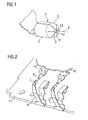
- FIG. 2 shows, a similar such electromechanical contact system is provided a second time. Since this is an identical electromechanical contact system, it is sufficient if only one of the two electromechanical contact systems or both are described in more detail at the same time. For physical reasons, for example, during charging two such electromechanical contact systems are necessary.
- the spring contact 8 with the first contact head 7 is part of a printed circuit board 11, which in turn is part of a charging tray, which here in the FIG. 2 not further explained.
- the rigidly mounted, the second contact head 9 having mating contact 10 is part of a printed circuit board 12, which in turn is part of a mobile communication terminal, which here in the FIG. 2 not further explained.
- FIG. 2 is a point in time shown, in which the mobile communication terminal is set in the charging cradle and shortly before an electromechanical contact via its rigidly mounted, the second contact heads 9 having mating contacts 10 with the first contact heads 7 having spring contacts 8.
- FIG. 2 The in the FIG. 2 The arrangement shown is to be understood in such a way that the mobile communication terminal is set vertically from above into the charger, so that the mobile communication terminal with its own weight operates the electromechanical contact system between the mobile communication terminal and the charger.
- the rigidly mounted mating contacts 10 press with their contact heads 9, the spring contacts 8 on the contact heads 7 resiliently back.
- the mobile communication terminal is only temporarily set in the charger, so that in total the first contact heads 7 of the spring contacts 8 contact the second contact heads 9 of the rigidly mounted mating contacts 10 only in such periods, in which the mobile communication terminal is set in the charger.
- the contact heads 7 of the spring contacts 8 and the contact heads 9 of the rigidly mounted mating contacts 10 are formed identically in the embodiment described herein from the geometric dimensions, in the manner in which the contact head 1 from the FIG. 1 is trained.
- the contact tabs 6 of the first contact head 7 and the second contact head 8 ends at a distance 13 in front of the central longitudinal axis. 3 the cylindrical shape 4 of the first contact head 7 and second contact head 9th
- the contact lobes 6 terminating in front of the central longitudinal axis 3 of the cylindrical shape 4 of the first contact head 7 and the second contact head 9 enclose therebetween an opening 14 arranged symmetrically with respect to the longitudinal axis 3 of the cylindrical shape 4 of the first contact head 7 and the second contact head 9, respectively.
- the opening 14 enclosed by the contact tabs 6 of the first contact head 7 and the second contact head 9 is at least substantially circular.
Landscapes
- Engineering & Computer Science (AREA)
- Manufacturing & Machinery (AREA)
- Contacts (AREA)
- Charge And Discharge Circuits For Batteries Or The Like (AREA)
- Measuring Leads Or Probes (AREA)
Abstract
Description
- Die Erfindung betrifft ein elektromechanisches Kontaktsystem für sehr kleine Kontaktkräfte gemäß dem Oberbegriff des Anspruchs 1.
- Mobile Kommunikationsendgeräte werden immer kleiner und leichter gebaut.
- Zum Laden der mobilen Kommunikationsendgeräte werden sie in ein zugehöriges Ladegerät eingestellt.
- Zwischen dem Ladegerät und dem in das Ladegerät eingestellten mobilen Kommunikationsendgerät befindet sich ein elektromechanisches Kontaktsystem, das es ermöglicht, dass Ladeenergie seitens des Ladegeräts in das in das Ladegerät eingestellte mobile Kommunikationsendgerät übertragen werden kann. Dabei stellt das zwischen dem Ladegerät und dem in das Ladegerät eingestellten mobilen Kommunikationsendgerät befindliche elektromechanische Kontaktsystem einen elektromechanischen Kontakt zwischen dem Ladegerät und dem in das Ladegerät eingestellten mobilen Kommunikationsendgerät mit einer Kraft her, die durch das Eigengewicht des mobilen Kommunikationsendgeräts bestimmt ist. Da die mobilen Kommunikationsendgeräte, wie eingangs schon erwähnt, immer kleiner und leichter werden, ist diese Kraft sehr klein und wird auch immer kleiner, das heißt, sie liegt heute schon bei unter 0,3 N. Kräfte > 0,3 N sind Standard-Kontaktkräfte.
- Bekannt sind elektromechanische Kontaktsysteme, die einen einen ersten Kontaktkopf aufweisenden Federkontakt aufweisen, der im Ladegerät platziert ist, und die einen einen zweiten Kontaktkopf aufweisenden starren Gegenkontakt aufweisen, der im mobilen Kommunikationsendgerät platziert ist.
- Im eingestellten Zustand des mobilen Kommunikationsendgeräts in das Ladegerät kontaktiert der zweite Kontaktkopf des starren Gegenkontakts des mobilen Kommunikationsendgeräts den ersten Kontaktkopf des Federkontakts des Ladegeräts elektromechanisch mit der durch das Eigengewicht des mobilen Kommunikationsendgeräts bestimmten Kraft.
- An dieser Stelle sei der Vollständigkeit wegen erwähnt, dass in einem Ladegerät und in einem mobilen Kommunikationsendgerät jeweils zwei solcher elektromechanischer Kontaktsysteme für eine letztendliche Bewerkstelligung eines Stromtransports zwischen dem Ladegerät und dem in das Ladegerät eingestellten mobilen Kommunikationsendgerät vorhanden sind.
- Das mobile Kommunikationsendgerät ist nicht ständig in das Ladegerät eingestellt. Es wird nur in Zeitabschnitten in das Ladegerät eingestellt. Es wird in solchen Zeitabschnitten in das Ladegerät eingestellt, in denen das mobile Kommunikationsendgerät zu laden ist. Die Kontakte des zwischen dem Ladegerät und dem in das Ladegerät eingestellten mobilen Kommunikationsendgerät platzierten elektromechanischen Kontaktsystems kontaktieren daher auch nur in diesen Zeitabschnitten miteinander.
- Aus dem Dokument
DE 1 233 944 B ist im Zusammenhang mit einer Relaissteuerung ein elektromechanisches Kontaktsystem bekannt, das rein bezogen auf das Kontaktieren selbst dem Prinzip des oben im Zusammenhang mit einem Lade- und einem Kommunikationsendgerät beschriebenen elektromechanischen Kontaktsystem entspricht. - Ein Nachteil von elektrischen Kontakten ist, dass sie im Laufe der Zeit oxidieren.
- Auf Grund der Tatsache, dass die Kontaktkraft im elektromechanischen Kontaktsystem zwischen der Ladeschale und dem in die Ladeschale eingestellten mobilen Kommunikationsendgerät wegen des geringen Eigengewichts des mobilen Kommunikationsendgeräts sehr klein ist, können bereits geringste Oxidationsschichten auf den Kontaktköpfen des elektromechanischen Kontaktsystems dazu führen, dass der elektrische Kontakt zwischen den Kontaktköpfen möglicherweise zuerst immer schlechter, letztlich jedoch vollständig unterbrochen wird. Die kraftschlüssige Verbindung im elektromechanischen Kontaktsystem reicht hier nicht mehr aus, die gebildeten Oxidationsschichten durch Druck zu durchdringen beziehungsweise weg zu reiben.
- Um auch bei sehr geringen Kontaktkräften, wie oben angesprochen, zu gewährleisten, dass auch über einen längeren Nutzungsdauerzeitraum des mobilen Kommunikationsendgeräts sichergestellt ist, dass bei einem Einstellen des mobilen Kommunikationsendgeräts in das Ladegerät ein sicherer elektromechanischer Kontakt im vorhandenen elektromechanischen Kontaktsystem zwischen dem Ladegerät und dem mobilen Kommunikationsendgerät entsteht, werden heute die Kontaktköpfe des elektromechanischen Kontaktsystems vergoldet. Eine Vergoldung der betreffenden Kontaktköpfe ist wirtschaftlich jedoch sehr teuer.
- Aus dem Dokument
US 6 241 559 B1 ist ein elektromechanisches Kontaktsystem bekannt, welches zwei Kontaktköpfe aufweist, von denen mindestens einer starr gelagert ist. Ein solcher starr gelagerter Kontaktkopf kann dabei als Hohlzylinder ausgeführt sein. - Aus dem Dokument
DE 88 05 527 U1 ist ein für elektrische Kontaktierungen verwendbarer Kontakt bekannt, der an einem freien Ende mit einer aus nach innen gebogenen Lappen bestehenden Spitze versehen ist. - Aus dem Dokument
DE 34 47 654 ist ein weiterer für elektrische Kontaktierungen verwendbarer hohlzylindrisch gerollter Kontakt mit an einem freien Ende gebogenen Kontaktlappen bekannt. - Aus dem Dokument
DE 86 04 142 U1 ist schließlich ein für elektrische Kontaktierungen verwendbarer hohlzylindrischer Kontakt bekannt, der aus Neusilber besteht. - Aufgabe der vorliegenden Erfindung ist es, ausgehend von einem elektromechanischen Kontaktsystem der eingangs genannten Art, ein solches elektromechanisches Kontaktsystem kostengünstig derart technisch zu verbessern, dass stets eine sichere elektromechanische Kontaktierung auch bei sehr geringen Kontaktkräften gewährleistet ist.
- Diese Aufgabe wird erfindungsgemäß durch ein elektromechanisches Kontaktsystem gelöst, das die im Kennzeichen des Anspruchs 1 angegebenen Merkmale aufweist.
- Bei einem solchen elektromechanischen Kontaktsystem ist zumindest der erste Kontaktkopf des Federkontakts oder zumindest der zweite Kontaktkopf des starr gelagerten Gegenkontakts als hohl zylindrisch gerollter Kontaktkopf mit am freien Ende so einwärts in Richtung zentrale Längsachse der Zylinderform des Kontaktkopfs hin in einer Rundung gebogenen Kontaktlappen ausgebildet, dass diese am freien Ende eine Öffnung umschließen. Außerdem ist der Federkontakt mit erstem Kontaktkopf aus unbeschichtetem Chrom-Nickel-Stahl und ist der Gegenkontakt mit zweitem Kontaktkopf aus unbeschichtetem Neusilber gebildet.
- Die hier verwendeten Materialien für den Federkontakt beziehungsweise den Gegenkontakt beziehungsweise für jeweils deren Kontaktköpfe sind kostengünstiger als vergoldete Kontaktköpfe. Außerdem bleibt durch die Verwendung von unbeschichtetem Chrom-Nickel-Stahl nicht nur die elektrische Leitfähigkeit sondern auch die Federwirkung des Federkontakts erhalten. Schließlich bleibt durch die Verwendung von unbeschichtetem Neusilber auch die elektrische Leitfähigkeit des Gegenkontakts erhalten.
- Durch die Kombination von unbeschichtetem Neusilber beim zweiten Kontaktkopf des starr gelagerten Gegenkontakts im mobilen Kommunikationsendgerät und unbeschichtetem Chrom-Nickel-Stahl beim ersten Kontaktkopf des Federkontakts im Ladegerät auf der einen Seite und der besonderen geometrischen Form der eingesetzten Kontaktköpfe als hohl zylindrisch gerollter Kontaktkopf mit im Kontaktbereich nach innen zum Zentrum der Zylinderform hin offen in einer Rundung eingebogenen Kontaktlappen auf der anderen Seite wird ohne Funktionseinschränkung und auf Dauer eine sichere elektromechanische Kontaktierung auch bei Kontaktkräften < 0,3 N gewährleistet.
- Die Kontaktlappen der Kontaktköpfe sind offen in einer Rundung eingebogen, das heißt frei endend eingebogen, wodurch sie eine Ausgleichsbewegung ausführen können. Durch diese Bewegungsausgleichsfähigkeit sorgen die Kontaktlappen der Kontaktköpfe beim gegenseitigen Kontaktieren der jeweiligen Kontaktköpfe von Federkontakt und starr gelagertem Gegenkontakt für einen geringen gegenseitigen mechanischen Abrieb, durch den eventuell vorhandene Oxidationsschichten auf den Kontaktköpfen an den Kontaktstellen immer wieder beseitigt werden.
- Außerdem verändern sich durch die Bewegungsausgleichsfähigkeit der Kontaktlappen auch immer wieder die tatsächlichen Kontaktpunkte zwischen den Kontaktköpfen. Dadurch tritt nur eine geringe Kontakt-Spurbildung auf, was einen geringen Verschleiß der Kontaktpunkte bedeutet.
- Durch die erfindungsgemäßen Maßnahmen ist es insgesamt möglich, auch bei Kontaktkräften von < 0,3 N stetig eine sichere elektromechanische Kontaktierung im hier zu Grunde liegenden elektromechanischen Kontaktsystem bei niedrigen Herstellungskosten zu gewährleisten.
- Die Kontakte des elektromechanischen Kontaktsystems müssen bei Kontaktkräften < 0,3 N nicht mehr vergoldet werden.
- Vorteilhafte Ausgestaltungen der Erfindung sind Gegenstand von Unteransprüchen.
- Danach ist sowohl der erste Kontaktkopf des Federkontakts als auch der zweite Kontaktkopf des starr gelagerten Gegenkontakts als hohl zylindrisch gerollter Kontaktkopf mit am freien Ende so einwärts in Richtung zentrale Längsachse der Zylinderform des Kontaktkopfs hin in einer Rundung gebogenen Kontaktlappen ausgebildet, dass diese am freien Ende eine Öffnung umschließen. Auf diese Weise sind die oben angesprochenen erwünschten Effekte mit doppelter, also verstärkter Wirkung vorhanden.
- Bei einer weiteren vorteilhaften Ausgestaltung des erfindungsgemäßen elektromechanischen Kontaktsystems enden die Kontaktlappen des ersten und/oder des zweiten Kontaktkopfs mit Abstand vor der zentralen Längsachse der Zylinderform des ersten und/oder zweiten Kontaktkopfs. Hierdurch gibt es einen offenen Mittelpunkt im Kontaktbereich des Kontaktkopfs, der bei einer elektromechanischen Kontaktierung dafür sorgt, dass die elektromechanische Kontaktierung nicht mehr nur über eine punktuelle Kontaktierung sondern über eine linienförmige Kontaktierung passiert. Damit ergibt sich ein wesentlich verbesserter elektrischer Kontakt an der Kontaktierungsstelle.
- Wird eine symmetrisch zur Längsachse der Zylinderform des ersten und/oder zweiten Kontaktkopfs angeordnete Öffnung als offener Mittelpunkt vorgesehen, lassen sich wegen der symmetrischen Ausbildung der Öffnung die Kontaktköpfe besonders einfach, beispielsweise durch Rollen der Kontaktköpfe, realisieren.
- Eine wenigstens kreisähnliche Ausgestaltung der von den Kontaktlappen umschlossenen Öffnung ergibt sich quasi automatisch bei einem Rollen der Kontaktköpfe, so dass hierfür kein zusätzlicher Aufwand für deren Herstellung betrieben werden muss.
- Nachfolgend wird ein Ausführungsbeispiel der Erfindung anhand einer Zeichnung näher erläutert. Darin zeigen:
- Figur 1
- einen einzelnen Kontaktkopf gemäß der Erfindung in dreidimensionaler vergrößerter Darstellung, und
- Figur 2
- ein elektromechanisches Kontaktsystem gemäß der Erfindung in Prinzipdarstellung.
- Der in der
Figur 1 dargestellte Kontaktkopf 1 ist ein hohl zylindrisch gerollter Kontaktkopf mit zum freien Ende 2 hin offen einwärts in Richtung zentrale Längsachse 3 der Zylinderform 4 des Kontaktkopfs 1 hin in einer Rundung 5 gebogenen Kontaktlappen 6. - In der
Figur 2 ist ein elektromechanisches Kontaktsystem für sehr kleine mechanische Kontaktkräfte gezeigt, welches einen einen ersten Kontaktkopf 7 aufweisenden Federkontakt 8 und einen starr gelagerten, einen zweiten Kontaktkopf 9 aufweisenden Gegenkontakt 10 umfasst. Dabei ist der zweite Kontaktkopf 9 dem ersten Kontaktkopf 7 zugeordnet. - Wie die
Figur 2 zeigt, ist ein gleiches solches elektromechanische Kontaktsystem ein zweites Mal vorgesehen. Da es sich hierbei um ein identisches elektromechanisches Kontaktsystem handelt, genügt es, wenn nur eines der beiden elektromechanischen Kontaktsysteme beziehungsweise beide gleichzeitig näher beschrieben wird beziehungsweise werden. Aus physikalischen Gründen sind zum Beispiel bei Ladevorgängen zwei solcher elektromechanischen Kontaktsysteme notwendig. - Der Federkontakt 8 mit dem ersten Kontaktkopf 7 ist Teil einer Flachbaugruppe 11, die wiederum Teil einer Ladeschale ist, die hier in der
Figur 2 nicht weiter ausgeführt ist. - Der starr gelagerte, den zweiten Kontaktkopf 9 aufweisende Gegenkontakt 10 ist Teil einer Flachbaugruppe 12, die wiederum Teil eines mobilen Kommunikationsendgerät ist, das hier in der
Figur 2 nicht weiter ausgeführt ist. - In der
Figur 2 ist ein Zeitpunkt gezeigt, in dem das mobile Kommunikationsendgerät in die Ladeschale eingestellt wird und kurz vor einer elektromechanischen Kontaktierung über seine starr gelagerten, die zweiten Kontaktköpfe 9 aufweisenden Gegenkontakte 10 mit den die ersten Kontaktköpfe 7 aufweisenden Federkontakte 8 steht. - Die in der
Figur 2 gezeigte Anordnung ist in der Weise zu verstehen, dass das mobile Kommunikationsendgerät senkrecht von oben in das Ladegerät eingestellt ist, so dass das mobile Kommunikationsendgerät mit seinem Eigengewicht das elektromechanische Kontaktsystem zwischen dem mobilen Kommunikationsendgerät und dem Ladegerät bedient. Dabei drücken die starr gelagerten Gegenkontakte 10 mit ihren Kontaktköpfen 9 die Federkontakte 8 über deren Kontaktköpfe 7 federnd zurück. - Das mobile Kommunikationsendgerät ist nur zeitweise in das Ladegerät eingestellt, so dass in Summe die ersten Kontaktköpfe 7 der Federkontakte 8 die zweiten Kontaktköpfe 9 der starr gelagerten Gegenkontakte 10 nur jeweils in solchen Zeitabschnitten kontaktieren, in denen das mobile Kommunikationsendgerät in das Ladegerät eingestellt ist.
- Die Kontaktköpfe 7 der Federkontakte 8 und die Kontaktköpfe 9 der starr gelagerten Gegenkontakte 10 sind im hier beschriebenen Ausführungsbeispiel von den geometrischen Abmessungen her identisch ausgebildet, und zwar in der Weise, wie der Kontaktkopf 1 aus der
Figur 1 ausgebildet ist. - Dabei besteht der Federkontakt 8 mit dem ersten Kontaktkopf 7 aus unbeschichtetem Chrom-Nickel-Stahl, und besteht der starr gelagerte Gegenkontakt 10 mit dem zweiten Kontaktkopf 9 aus unbeschichtetem Neusilber.
- Wie die
Figur 1 näher zeigt, enden die Kontaktlappen 6 des ersten Kontaktkopfs 7 beziehungsweise des zweiten Kontaktkopfs 8 mit einem Abstand 13 vor der zentralen Längsachse 3 der Zylinderform 4 des ersten Kontaktkopfs 7 beziehungsweise zweiten Kontaktkopfs 9. - Dadurch umschließen die vor der zentralen Längsachse 3 der Zylinderform 4 des ersten Kontaktkopfs 7 beziehungsweise des zweiten Kontaktkopfs 9 endenden Kontaktlappen 6 zwischen sich eine symmetrisch zur Längsachse 3 der Zylinderform 4 des ersten Kontaktkopfs 7 beziehungsweise des zweiten Kontaktkopfs 9 angeordnete Öffnung 14.
- Durch das Rollen der Kontaktköpfe 7 beziehungsweise 9 ist die von den Kontaktlappen 6 des ersten Kontaktkopfs 7 beziehungsweise des zweiten Kontaktkopfs 9 umschlossene Öffnung 14 wenigstens im Wesentlichen kreisrund ausgebildet.
Claims (5)
- Elektromechanisches Kontaktsystem für mechanische Kontaktkräfte < 0,3 N, aufweisend einen ersten Kontaktkopf aufweisenden Federkontakt und einen starr gelagerten, einen zweiten Kontaktkopf aufweisenden Gegenkontakt, dessen zweiter Kontaktkopf den ersten Kontaktkopf des Federkontakts in Zeitabschnitten kontaktiert, dadurch gekennzeichnet, dass zumindest der erste Kontaktkopf (7) des Federkontakts (8) oder zumindest der zweite Kontaktkopf (9) des starr gelagerten Gegenkontakts (10) als hohl zylindrisch gerollter Kontaktkopf (7; 9) mit am freien Ende (2) so einwärts in Richtung zentrale Längsachse (3) der Zylinderform (4) des Kontaktkopfs (7; 9) hin in einer Rundung (5) gebogenen Kontaktlappen (6) ausgebildet ist, dass diese am freien Ende (2) eine Öffnung (14) umschließen, dass der Federkontakt (8) mit erstem Kontaktkopf (7) aus unbeschichtetem Chrom-Nickel-Stahl gebildet ist, und dass der starr gelagerte Gegenkontakt (10) mit zweitem Kontaktkopf (9) aus unbeschichtetem Neusilber gebildet ist.
- Elektromechanisches Kontaktsystem nach Anspruch 1, dadurch gekennzeichnet, dass sowohl der erste Kontaktkopf (7) des Federkontakts (8) als auch der zweite Kontaktkopf (9) des starr gelagerten Gegenkontakts (10) als hohl zylindrisch gerollter Kontaktkopf (7; 9) mit am freien Ende (2) so einwärts in Richtung zentrale Längsachse (3) der Zylinderform (4) des Kontaktkopfs (7; 9) hin in einer Rundung (5) gebogenen Kontaktlappen (6) ausgebildet ist, dass diese am freien Ende (2) eine Öffnung (14) umschließen.
- Elektromechanisches Kontaktsystem nach Anspruch 1 oder 2, dadurch gekennzeichnet, dass die Kontaktlappen (6) des ersten und/oder des zweiten Kontaktkopfs (7; 9) mit Abstand (13) vor der zentralen Längsachse (3) der Zylinderform (4) des ersten und/oder zweiten Kontaktkopfs (7; 9) enden.
- Elektromechanisches Kontaktsystem nach Anspruch 3, dadurch gekennzeichnet, dass die zentrale Längsachse (3) der Zylinderform (4) des ersten und/oder zweiten Kontaktkopfs (7; 9) durch den Mittelpunkt der Öffnung (14) verläuft, welche die vor dieser Längsachse (3) endenden Kontaktlappen (6) umschließen.
- Elektromechanisches Kontaktsystem nach Anspruch 4, dadurch gekennzeichnet, dass die von den Kontaktlappen (6) des ersten und/oder zweiten Kontaktkopfs (7; 9) umschlossene Öffnung (14) kreisähnlich ist.
Applications Claiming Priority (1)
| Application Number | Priority Date | Filing Date | Title |
|---|---|---|---|
| DE102007009205A DE102007009205B3 (de) | 2007-02-26 | 2007-02-26 | Elektromechanisches Kontaktsystem für sehr kleine mechanische Kontaktkräfte |
Publications (3)
| Publication Number | Publication Date |
|---|---|
| EP1962384A2 true EP1962384A2 (de) | 2008-08-27 |
| EP1962384A3 EP1962384A3 (de) | 2010-06-16 |
| EP1962384B1 EP1962384B1 (de) | 2012-02-01 |
Family
ID=39363437
Family Applications (1)
| Application Number | Title | Priority Date | Filing Date |
|---|---|---|---|
| EP08101667A Not-in-force EP1962384B1 (de) | 2007-02-26 | 2008-02-15 | Elektromechanisches Kontaktsystem für sehr kleine mechanische Kontaktkräfte |
Country Status (3)
| Country | Link |
|---|---|
| EP (1) | EP1962384B1 (de) |
| AT (1) | ATE544200T1 (de) |
| DE (1) | DE102007009205B3 (de) |
Cited By (1)
| Publication number | Priority date | Publication date | Assignee | Title |
|---|---|---|---|---|
| CN110914102A (zh) * | 2017-07-14 | 2020-03-24 | 易链接有限责任公司 | 用于建立车辆接触单元的电连接的方法、车辆连接设备和车辆 |
Citations (5)
| Publication number | Priority date | Publication date | Assignee | Title |
|---|---|---|---|---|
| DE1233944B (de) | 1963-04-23 | 1967-02-09 | Siemens Ag | Vorrichtung zur Betaetigung von Kontakt-federsaetzen bei elektromagnetischen Relais |
| DE3447654A1 (de) | 1983-12-29 | 1985-07-11 | Trw Inc., Redondo Beach, Calif. | Elektrischer stecker |
| DE8604142U1 (de) | 1986-02-15 | 1987-08-27 | Robert Bosch Gmbh, 70469 Stuttgart | Koaxialer Winkelstecker |
| DE8805527U1 (de) | 1988-04-26 | 1988-06-23 | Siemens Ag, 1000 Berlin Und 8000 Muenchen | Kontaktelement für eine elektrische Steckverbindung |
| US6241559B1 (en) | 1993-09-16 | 2001-06-05 | Strix Limited | Cordless electrical appliances and connectors therefor |
Family Cites Families (4)
| Publication number | Priority date | Publication date | Assignee | Title |
|---|---|---|---|---|
| DE880905C (de) * | 1945-02-20 | 1953-06-25 | Siemens Ag | Mehrpolige Steckverbindung |
| US4778404A (en) * | 1983-12-27 | 1988-10-18 | Amp Incorporated | Spring terminal |
| US5366380A (en) * | 1989-06-13 | 1994-11-22 | General Datacomm, Inc. | Spring biased tapered contact elements for electrical connectors and integrated circuit packages |
| US5980335A (en) * | 1998-03-27 | 1999-11-09 | Molex Incorporated | Electrical terminal |
-
2007
- 2007-02-26 DE DE102007009205A patent/DE102007009205B3/de not_active Expired - Fee Related
-
2008
- 2008-02-15 EP EP08101667A patent/EP1962384B1/de not_active Not-in-force
- 2008-02-15 AT AT08101667T patent/ATE544200T1/de active
Patent Citations (5)
| Publication number | Priority date | Publication date | Assignee | Title |
|---|---|---|---|---|
| DE1233944B (de) | 1963-04-23 | 1967-02-09 | Siemens Ag | Vorrichtung zur Betaetigung von Kontakt-federsaetzen bei elektromagnetischen Relais |
| DE3447654A1 (de) | 1983-12-29 | 1985-07-11 | Trw Inc., Redondo Beach, Calif. | Elektrischer stecker |
| DE8604142U1 (de) | 1986-02-15 | 1987-08-27 | Robert Bosch Gmbh, 70469 Stuttgart | Koaxialer Winkelstecker |
| DE8805527U1 (de) | 1988-04-26 | 1988-06-23 | Siemens Ag, 1000 Berlin Und 8000 Muenchen | Kontaktelement für eine elektrische Steckverbindung |
| US6241559B1 (en) | 1993-09-16 | 2001-06-05 | Strix Limited | Cordless electrical appliances and connectors therefor |
Cited By (1)
| Publication number | Priority date | Publication date | Assignee | Title |
|---|---|---|---|---|
| CN110914102A (zh) * | 2017-07-14 | 2020-03-24 | 易链接有限责任公司 | 用于建立车辆接触单元的电连接的方法、车辆连接设备和车辆 |
Also Published As
| Publication number | Publication date |
|---|---|
| ATE544200T1 (de) | 2012-02-15 |
| EP1962384B1 (de) | 2012-02-01 |
| EP1962384A3 (de) | 2010-06-16 |
| DE102007009205B3 (de) | 2008-06-12 |
Similar Documents
| Publication | Publication Date | Title |
|---|---|---|
| DE112010005496B4 (de) | Verfahren zur Herstellung eines elektrischen Steckverbinders | |
| DE102013103818A1 (de) | Verfahren zur Herstellung von Einpresskontakten, Einpresskontakt sowie Bauteilanordnung mit zumindest einem Einpresskontakt | |
| DE102015201381A1 (de) | Kontaktelement | |
| DE102016112434A1 (de) | Elektrischer Hochleistungskontakt | |
| DE102008039066A1 (de) | Leistungsschalter mit verschwenkbarem Überbrückungselement | |
| DE102011003131A1 (de) | Elektrischer Schalter | |
| EP2297820B1 (de) | Schutzleiteranschlussvorrichtung aus metall | |
| DE112008004167T5 (de) | Verbindervorrichtung und diese verwendendes Steuerungszentrum | |
| EP1962384B1 (de) | Elektromechanisches Kontaktsystem für sehr kleine mechanische Kontaktkräfte | |
| EP2614556A1 (de) | Anschlussvorrichtung | |
| DE10108858B4 (de) | Schaltkontaktanordnung | |
| EP0471893A2 (de) | Kontaktfedersatz für hohe elektrische Ströme | |
| DE2025982A1 (de) | Mehrfach Kontaktstem fur Nocken schalter | |
| EP0752154B1 (de) | Leiterplattenrelais mit einpressanschlüssen | |
| DE2558308A1 (de) | Kontakteinheit mit einem festen und einem beweglichen kontakt fuer lastwaehler von elektrischen transformatoren | |
| DE102006043795B3 (de) | Elektrischer Mikroschalter | |
| DE2829891C2 (de) | Drucktastenschalter | |
| DE1277978B (de) | Elektrische Kontakt-Doppelhuelse | |
| DE202019105429U1 (de) | Kontaktvorrichtung zum Herstellen einer elektrisch leitenden Steckverbindung mit einem Kontaktelement | |
| DE1123011B (de) | Elektrischer Schalter fuer Schwachstrom mit einer Vielzahl von drahtfoermigen Kontakten | |
| DE1006486B (de) | Schalterelement zum Aufbau von elektrischen Kombinationsschaltern | |
| DE879870C (de) | Elektromagnetisches Relais | |
| DE19609480B4 (de) | Kabelkanaldeckel | |
| DE257927C (de) | ||
| DE2925653C2 (de) | Elektrischer Schalter |
Legal Events
| Date | Code | Title | Description |
|---|---|---|---|
| PUAI | Public reference made under article 153(3) epc to a published international application that has entered the european phase |
Free format text: ORIGINAL CODE: 0009012 |
|
| AK | Designated contracting states |
Kind code of ref document: A2 Designated state(s): AT BE BG CH CY CZ DE DK EE ES FI FR GB GR HR HU IE IS IT LI LT LU LV MC MT NL NO PL PT RO SE SI SK TR |
|
| AX | Request for extension of the european patent |
Extension state: AL BA MK RS |
|
| RAP1 | Party data changed (applicant data changed or rights of an application transferred) |
Owner name: GIGASET COMMUNICATIONS GMBH |
|
| PUAL | Search report despatched |
Free format text: ORIGINAL CODE: 0009013 |
|
| AK | Designated contracting states |
Kind code of ref document: A3 Designated state(s): AT BE BG CH CY CZ DE DK EE ES FI FR GB GR HR HU IE IS IT LI LT LU LV MC MT NL NO PL PT RO SE SI SK TR |
|
| AX | Request for extension of the european patent |
Extension state: AL BA MK RS |
|
| 17P | Request for examination filed |
Effective date: 20101105 |
|
| AKX | Designation fees paid |
Designated state(s): AT BE BG CH CY CZ DE DK EE ES FI FR GB GR HR HU IE IS IT LI LT LU LV MC MT NL NO PL PT RO SE SI SK TR |
|
| GRAP | Despatch of communication of intention to grant a patent |
Free format text: ORIGINAL CODE: EPIDOSNIGR1 |
|
| RIC1 | Information provided on ipc code assigned before grant |
Ipc: H01R 13/03 20060101AFI20110712BHEP Ipc: H01R 13/24 20060101ALI20110712BHEP Ipc: H01R 13/08 20060101ALI20110712BHEP Ipc: H01R 43/16 20060101ALI20110712BHEP |
|
| GRAS | Grant fee paid |
Free format text: ORIGINAL CODE: EPIDOSNIGR3 |
|
| GRAA | (expected) grant |
Free format text: ORIGINAL CODE: 0009210 |
|
| AK | Designated contracting states |
Kind code of ref document: B1 Designated state(s): AT BE BG CH CY CZ DE DK EE ES FI FR GB GR HR HU IE IS IT LI LT LU LV MC MT NL NO PL PT RO SE SI SK TR |
|
| REG | Reference to a national code |
Ref country code: GB Ref legal event code: FG4D Free format text: NOT ENGLISH |
|
| REG | Reference to a national code |
Ref country code: AT Ref legal event code: REF Ref document number: 544200 Country of ref document: AT Kind code of ref document: T Effective date: 20120215 Ref country code: CH Ref legal event code: EP |
|
| REG | Reference to a national code |
Ref country code: DE Ref legal event code: R096 Ref document number: 502008006268 Country of ref document: DE Effective date: 20120329 |
|
| REG | Reference to a national code |
Ref country code: NL Ref legal event code: VDEP Effective date: 20120201 |
|
| LTIE | Lt: invalidation of european patent or patent extension |
Effective date: 20120201 |
|
| PG25 | Lapsed in a contracting state [announced via postgrant information from national office to epo] |
Ref country code: LT Free format text: LAPSE BECAUSE OF FAILURE TO SUBMIT A TRANSLATION OF THE DESCRIPTION OR TO PAY THE FEE WITHIN THE PRESCRIBED TIME-LIMIT Effective date: 20120201 Ref country code: HR Free format text: LAPSE BECAUSE OF FAILURE TO SUBMIT A TRANSLATION OF THE DESCRIPTION OR TO PAY THE FEE WITHIN THE PRESCRIBED TIME-LIMIT Effective date: 20120201 Ref country code: IS Free format text: LAPSE BECAUSE OF FAILURE TO SUBMIT A TRANSLATION OF THE DESCRIPTION OR TO PAY THE FEE WITHIN THE PRESCRIBED TIME-LIMIT Effective date: 20120601 Ref country code: NO Free format text: LAPSE BECAUSE OF FAILURE TO SUBMIT A TRANSLATION OF THE DESCRIPTION OR TO PAY THE FEE WITHIN THE PRESCRIBED TIME-LIMIT Effective date: 20120501 Ref country code: NL Free format text: LAPSE BECAUSE OF FAILURE TO SUBMIT A TRANSLATION OF THE DESCRIPTION OR TO PAY THE FEE WITHIN THE PRESCRIBED TIME-LIMIT Effective date: 20120201 |
|
| REG | Reference to a national code |
Ref country code: IE Ref legal event code: FD4D |
|
| BERE | Be: lapsed |
Owner name: GIGASET COMMUNICATIONS G.M.B.H. Effective date: 20120228 |
|
| PG25 | Lapsed in a contracting state [announced via postgrant information from national office to epo] |
Ref country code: GR Free format text: LAPSE BECAUSE OF FAILURE TO SUBMIT A TRANSLATION OF THE DESCRIPTION OR TO PAY THE FEE WITHIN THE PRESCRIBED TIME-LIMIT Effective date: 20120502 Ref country code: LV Free format text: LAPSE BECAUSE OF FAILURE TO SUBMIT A TRANSLATION OF THE DESCRIPTION OR TO PAY THE FEE WITHIN THE PRESCRIBED TIME-LIMIT Effective date: 20120201 Ref country code: PL Free format text: LAPSE BECAUSE OF FAILURE TO SUBMIT A TRANSLATION OF THE DESCRIPTION OR TO PAY THE FEE WITHIN THE PRESCRIBED TIME-LIMIT Effective date: 20120201 Ref country code: PT Free format text: LAPSE BECAUSE OF FAILURE TO SUBMIT A TRANSLATION OF THE DESCRIPTION OR TO PAY THE FEE WITHIN THE PRESCRIBED TIME-LIMIT Effective date: 20120601 Ref country code: FI Free format text: LAPSE BECAUSE OF FAILURE TO SUBMIT A TRANSLATION OF THE DESCRIPTION OR TO PAY THE FEE WITHIN THE PRESCRIBED TIME-LIMIT Effective date: 20120201 |
|
| PG25 | Lapsed in a contracting state [announced via postgrant information from national office to epo] |
Ref country code: MC Free format text: LAPSE BECAUSE OF NON-PAYMENT OF DUE FEES Effective date: 20120229 Ref country code: CY Free format text: LAPSE BECAUSE OF FAILURE TO SUBMIT A TRANSLATION OF THE DESCRIPTION OR TO PAY THE FEE WITHIN THE PRESCRIBED TIME-LIMIT Effective date: 20120201 |
|
| REG | Reference to a national code |
Ref country code: CH Ref legal event code: PL |
|
| PG25 | Lapsed in a contracting state [announced via postgrant information from national office to epo] |
Ref country code: EE Free format text: LAPSE BECAUSE OF FAILURE TO SUBMIT A TRANSLATION OF THE DESCRIPTION OR TO PAY THE FEE WITHIN THE PRESCRIBED TIME-LIMIT Effective date: 20120201 Ref country code: DK Free format text: LAPSE BECAUSE OF FAILURE TO SUBMIT A TRANSLATION OF THE DESCRIPTION OR TO PAY THE FEE WITHIN THE PRESCRIBED TIME-LIMIT Effective date: 20120201 Ref country code: CH Free format text: LAPSE BECAUSE OF NON-PAYMENT OF DUE FEES Effective date: 20120229 Ref country code: SE Free format text: LAPSE BECAUSE OF FAILURE TO SUBMIT A TRANSLATION OF THE DESCRIPTION OR TO PAY THE FEE WITHIN THE PRESCRIBED TIME-LIMIT Effective date: 20120201 Ref country code: SI Free format text: LAPSE BECAUSE OF FAILURE TO SUBMIT A TRANSLATION OF THE DESCRIPTION OR TO PAY THE FEE WITHIN THE PRESCRIBED TIME-LIMIT Effective date: 20120201 Ref country code: IE Free format text: LAPSE BECAUSE OF FAILURE TO SUBMIT A TRANSLATION OF THE DESCRIPTION OR TO PAY THE FEE WITHIN THE PRESCRIBED TIME-LIMIT Effective date: 20120201 Ref country code: LI Free format text: LAPSE BECAUSE OF NON-PAYMENT OF DUE FEES Effective date: 20120229 Ref country code: RO Free format text: LAPSE BECAUSE OF FAILURE TO SUBMIT A TRANSLATION OF THE DESCRIPTION OR TO PAY THE FEE WITHIN THE PRESCRIBED TIME-LIMIT Effective date: 20120201 Ref country code: CZ Free format text: LAPSE BECAUSE OF FAILURE TO SUBMIT A TRANSLATION OF THE DESCRIPTION OR TO PAY THE FEE WITHIN THE PRESCRIBED TIME-LIMIT Effective date: 20120201 |
|
| PG25 | Lapsed in a contracting state [announced via postgrant information from national office to epo] |
Ref country code: SK Free format text: LAPSE BECAUSE OF FAILURE TO SUBMIT A TRANSLATION OF THE DESCRIPTION OR TO PAY THE FEE WITHIN THE PRESCRIBED TIME-LIMIT Effective date: 20120201 Ref country code: IT Free format text: LAPSE BECAUSE OF FAILURE TO SUBMIT A TRANSLATION OF THE DESCRIPTION OR TO PAY THE FEE WITHIN THE PRESCRIBED TIME-LIMIT Effective date: 20120201 |
|
| PLBE | No opposition filed within time limit |
Free format text: ORIGINAL CODE: 0009261 |
|
| STAA | Information on the status of an ep patent application or granted ep patent |
Free format text: STATUS: NO OPPOSITION FILED WITHIN TIME LIMIT |
|
| PG25 | Lapsed in a contracting state [announced via postgrant information from national office to epo] |
Ref country code: BE Free format text: LAPSE BECAUSE OF NON-PAYMENT OF DUE FEES Effective date: 20120228 |
|
| 26N | No opposition filed |
Effective date: 20121105 |
|
| REG | Reference to a national code |
Ref country code: DE Ref legal event code: R097 Ref document number: 502008006268 Country of ref document: DE Effective date: 20121105 |
|
| PG25 | Lapsed in a contracting state [announced via postgrant information from national office to epo] |
Ref country code: ES Free format text: LAPSE BECAUSE OF FAILURE TO SUBMIT A TRANSLATION OF THE DESCRIPTION OR TO PAY THE FEE WITHIN THE PRESCRIBED TIME-LIMIT Effective date: 20120512 |
|
| PG25 | Lapsed in a contracting state [announced via postgrant information from national office to epo] |
Ref country code: BG Free format text: LAPSE BECAUSE OF FAILURE TO SUBMIT A TRANSLATION OF THE DESCRIPTION OR TO PAY THE FEE WITHIN THE PRESCRIBED TIME-LIMIT Effective date: 20120501 Ref country code: MT Free format text: LAPSE BECAUSE OF FAILURE TO SUBMIT A TRANSLATION OF THE DESCRIPTION OR TO PAY THE FEE WITHIN THE PRESCRIBED TIME-LIMIT Effective date: 20120201 |
|
| REG | Reference to a national code |
Ref country code: AT Ref legal event code: MM01 Ref document number: 544200 Country of ref document: AT Kind code of ref document: T Effective date: 20130215 |
|
| PG25 | Lapsed in a contracting state [announced via postgrant information from national office to epo] |
Ref country code: TR Free format text: LAPSE BECAUSE OF FAILURE TO SUBMIT A TRANSLATION OF THE DESCRIPTION OR TO PAY THE FEE WITHIN THE PRESCRIBED TIME-LIMIT Effective date: 20120201 |
|
| PG25 | Lapsed in a contracting state [announced via postgrant information from national office to epo] |
Ref country code: LU Free format text: LAPSE BECAUSE OF NON-PAYMENT OF DUE FEES Effective date: 20120215 Ref country code: AT Free format text: LAPSE BECAUSE OF NON-PAYMENT OF DUE FEES Effective date: 20130215 |
|
| PG25 | Lapsed in a contracting state [announced via postgrant information from national office to epo] |
Ref country code: HU Free format text: LAPSE BECAUSE OF FAILURE TO SUBMIT A TRANSLATION OF THE DESCRIPTION OR TO PAY THE FEE WITHIN THE PRESCRIBED TIME-LIMIT Effective date: 20080215 |
|
| REG | Reference to a national code |
Ref country code: DE Ref legal event code: R082 Ref document number: 502008006268 Country of ref document: DE Representative=s name: MICHALSKI HUETTERMANN & PARTNER PATENTANWAELTE, DE Ref country code: DE Ref legal event code: R081 Ref document number: 502008006268 Country of ref document: DE Owner name: GIGASET COMMUNICATIONS GMBH, DE Free format text: FORMER OWNER: GIGASET COMMUNICATIONS GMBH, 81379 MUENCHEN, DE |
|
| REG | Reference to a national code |
Ref country code: FR Ref legal event code: PLFP Year of fee payment: 9 |
|
| PGFP | Annual fee paid to national office [announced via postgrant information from national office to epo] |
Ref country code: DE Payment date: 20160218 Year of fee payment: 9 |
|
| PGFP | Annual fee paid to national office [announced via postgrant information from national office to epo] |
Ref country code: FR Payment date: 20160218 Year of fee payment: 9 Ref country code: GB Payment date: 20160217 Year of fee payment: 9 |
|
| REG | Reference to a national code |
Ref country code: DE Ref legal event code: R119 Ref document number: 502008006268 Country of ref document: DE |
|
| GBPC | Gb: european patent ceased through non-payment of renewal fee |
Effective date: 20170215 |
|
| REG | Reference to a national code |
Ref country code: FR Ref legal event code: ST Effective date: 20171031 |
|
| PG25 | Lapsed in a contracting state [announced via postgrant information from national office to epo] |
Ref country code: DE Free format text: LAPSE BECAUSE OF NON-PAYMENT OF DUE FEES Effective date: 20170901 Ref country code: FR Free format text: LAPSE BECAUSE OF NON-PAYMENT OF DUE FEES Effective date: 20170228 |
|
| PG25 | Lapsed in a contracting state [announced via postgrant information from national office to epo] |
Ref country code: GB Free format text: LAPSE BECAUSE OF NON-PAYMENT OF DUE FEES Effective date: 20170215 |