EP1962384A2 - Système de contact électromécanique pour de très petites forces de contact mécaniques - Google Patents
Système de contact électromécanique pour de très petites forces de contact mécaniques Download PDFInfo
- Publication number
- EP1962384A2 EP1962384A2 EP08101667A EP08101667A EP1962384A2 EP 1962384 A2 EP1962384 A2 EP 1962384A2 EP 08101667 A EP08101667 A EP 08101667A EP 08101667 A EP08101667 A EP 08101667A EP 1962384 A2 EP1962384 A2 EP 1962384A2
- Authority
- EP
- European Patent Office
- Prior art keywords
- contact
- head
- electromechanical
- contact head
- spring
- Prior art date
- Legal status (The legal status is an assumption and is not a legal conclusion. Google has not performed a legal analysis and makes no representation as to the accuracy of the status listed.)
- Granted
Links
- MOFOBJHOKRNACT-UHFFFAOYSA-N nickel silver Chemical compound [Ni].[Ag] MOFOBJHOKRNACT-UHFFFAOYSA-N 0.000 claims abstract description 7
- 239000010956 nickel silver Substances 0.000 claims abstract description 7
- 229910000831 Steel Inorganic materials 0.000 claims abstract description 6
- 239000010959 steel Substances 0.000 claims abstract description 6
- 230000013011 mating Effects 0.000 claims description 20
- VNNRSPGTAMTISX-UHFFFAOYSA-N chromium nickel Chemical compound [Cr].[Ni] VNNRSPGTAMTISX-UHFFFAOYSA-N 0.000 claims description 5
- 229910052759 nickel Inorganic materials 0.000 abstract 1
- PXHVJJICTQNCMI-UHFFFAOYSA-N nickel Substances [Ni] PXHVJJICTQNCMI-UHFFFAOYSA-N 0.000 abstract 1
- 238000010295 mobile communication Methods 0.000 description 30
- 230000003647 oxidation Effects 0.000 description 3
- 238000007254 oxidation reaction Methods 0.000 description 3
- 230000000694 effects Effects 0.000 description 2
- PCHJSUWPFVWCPO-UHFFFAOYSA-N gold Chemical compound [Au] PCHJSUWPFVWCPO-UHFFFAOYSA-N 0.000 description 2
- 229910052737 gold Inorganic materials 0.000 description 2
- 239000010931 gold Substances 0.000 description 2
- 238000004519 manufacturing process Methods 0.000 description 2
- 238000005096 rolling process Methods 0.000 description 2
- 240000001439 Opuntia Species 0.000 description 1
- 235000004727 Opuntia ficus indica Nutrition 0.000 description 1
- 238000005299 abrasion Methods 0.000 description 1
- 230000015572 biosynthetic process Effects 0.000 description 1
- 238000004891 communication Methods 0.000 description 1
- 230000001419 dependent effect Effects 0.000 description 1
- 230000009760 functional impairment Effects 0.000 description 1
- 239000000463 material Substances 0.000 description 1
- 238000007747 plating Methods 0.000 description 1
Images
Classifications
-
- H—ELECTRICITY
- H01—ELECTRIC ELEMENTS
- H01R—ELECTRICALLY-CONDUCTIVE CONNECTIONS; STRUCTURAL ASSOCIATIONS OF A PLURALITY OF MUTUALLY-INSULATED ELECTRICAL CONNECTING ELEMENTS; COUPLING DEVICES; CURRENT COLLECTORS
- H01R13/00—Details of coupling devices of the kinds covered by groups H01R12/70 or H01R24/00 - H01R33/00
- H01R13/02—Contact members
- H01R13/03—Contact members characterised by the material, e.g. plating, or coating materials
-
- H—ELECTRICITY
- H01—ELECTRIC ELEMENTS
- H01R—ELECTRICALLY-CONDUCTIVE CONNECTIONS; STRUCTURAL ASSOCIATIONS OF A PLURALITY OF MUTUALLY-INSULATED ELECTRICAL CONNECTING ELEMENTS; COUPLING DEVICES; CURRENT COLLECTORS
- H01R13/00—Details of coupling devices of the kinds covered by groups H01R12/70 or H01R24/00 - H01R33/00
- H01R13/02—Contact members
- H01R13/04—Pins or blades for co-operation with sockets
- H01R13/08—Resiliently-mounted rigid pins or blades
-
- H—ELECTRICITY
- H01—ELECTRIC ELEMENTS
- H01R—ELECTRICALLY-CONDUCTIVE CONNECTIONS; STRUCTURAL ASSOCIATIONS OF A PLURALITY OF MUTUALLY-INSULATED ELECTRICAL CONNECTING ELEMENTS; COUPLING DEVICES; CURRENT COLLECTORS
- H01R13/00—Details of coupling devices of the kinds covered by groups H01R12/70 or H01R24/00 - H01R33/00
- H01R13/02—Contact members
- H01R13/22—Contacts for co-operating by abutting
- H01R13/24—Contacts for co-operating by abutting resilient; resiliently-mounted
- H01R13/2464—Contacts for co-operating by abutting resilient; resiliently-mounted characterized by the contact point
- H01R13/2471—Contacts for co-operating by abutting resilient; resiliently-mounted characterized by the contact point pin shaped
-
- H—ELECTRICITY
- H01—ELECTRIC ELEMENTS
- H01R—ELECTRICALLY-CONDUCTIVE CONNECTIONS; STRUCTURAL ASSOCIATIONS OF A PLURALITY OF MUTUALLY-INSULATED ELECTRICAL CONNECTING ELEMENTS; COUPLING DEVICES; CURRENT COLLECTORS
- H01R43/00—Apparatus or processes specially adapted for manufacturing, assembling, maintaining, or repairing of line connectors or current collectors or for joining electric conductors
- H01R43/16—Apparatus or processes specially adapted for manufacturing, assembling, maintaining, or repairing of line connectors or current collectors or for joining electric conductors for manufacturing contact members, e.g. by punching and by bending
Definitions
- the invention relates to an electromechanical contact system for very small contact forces according to the preamble of claim 1.
- an electromechanical contact system which allows charging energy can be transferred from the charger in the set in the charger mobile communication terminal.
- the electromechanical contact system located between the charger and the mobile communication terminal set in the charger establishes an electromechanical contact between the charger and the mobile communication terminal set in the charger with a force determined by the weight of the mobile communication terminal. Since the mobile communication terminals, as already mentioned, are getting smaller and lighter, this force is very small and is also getting smaller, that is, it is already below 0.3 N. forces> 0.3 N are standard Contact forces.
- Electromechanical contact systems which have a first contact head having a spring contact, which is placed in the charger, and having a second contact head having a rigid mating contact, which is placed in the mobile communication terminal.
- the second contact head of the rigid mating contact of the mobile communication terminal contacted the first contact head of the spring contact of the charger electromechanically with the determined by the weight of the mobile communication terminal power.
- the mobile communication terminal is not constantly set in the charger. It will only be set in the charger at intervals. It is set in such periods in the charger in which the mobile communication terminal is to load.
- the contacts of the electromechanical contact system placed between the charger and the mobile communication terminal set in the charger therefore also contact one another only in these time periods.
- a disadvantage of electrical contacts is that they oxidize over time.
- Object of the present invention is based on an electromechanical contact system of the type mentioned, such an electromechanical contact system cost so technically to improve technically that always a secure electromechanical contact is guaranteed even at very low contact forces.
- At least the first contact head of the spring contact or at least the second contact head of the rigidly mounted mating contact is formed as a hollow cylindrical rolled contact head with a curved at the free end inwardly towards the central longitudinal axis of the cylindrical shape of the contact head in a rounding contact lobe, that these enclose an opening at the free end.
- the spring contact with the first contact head of uncoated chromium-nickel steel and the mating contact with a second contact head is made of uncoated nickel silver.
- the materials used here for the spring contact or the mating contact or for each of their contact heads are cheaper than gold-plated contact heads.
- the use of uncoated chromium-nickel steel not only the electrical conductivity but also the spring action of the spring contact is maintained.
- the use of uncoated nickel silver also maintains the electrical conductivity of the mating contact.
- the contact lugs of the contact heads are open in a curve inflected, that is inflected freely ending, whereby they can perform a compensating movement.
- the contacts of the electromechanical contact system no longer need to be gold plated for contact forces ⁇ 0.3 N.
- both the first contact head of the spring contact and the second contact head of the rigidly mounted mating contact is formed as a hollow cylindrical rolled contact head at the free end so inwardly towards the central longitudinal axis of the cylindrical shape of the contact head in a rounding curved contact lobe that this at the free end of a Enclose opening.
- the contact lugs of the first and / or the second contact head end at a distance in front of the central longitudinal axis of the cylindrical shape of the first and / or second contact head.
- the contact heads can be realized particularly simply, for example by rolling the contact heads, because of the symmetrical design of the opening.
- An at least circular configuration of the opening enclosed by the contact lobes results more or less automatically when the contact heads roll, so that no additional effort has to be made for their production.
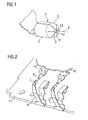
- the Indian FIG. 1 Contact head 1 shown is a hollow cylindrical rolled contact head with the free end 2 open towards inward toward the central longitudinal axis 3 of the cylindrical shape 4 of the contact head 1 out in a rounding 5 bent contact lobe. 6
- an electromechanical contact system for very small mechanical contact forces which comprises a first contact head 7 having a spring contact 8 and a rigidly mounted, a second contact head 9 having mating contact 10.
- the second contact head 9 is assigned to the first contact head 7.
- FIG. 2 shows, a similar such electromechanical contact system is provided a second time. Since this is an identical electromechanical contact system, it is sufficient if only one of the two electromechanical contact systems or both are described in more detail at the same time. For physical reasons, for example, during charging two such electromechanical contact systems are necessary.
- the spring contact 8 with the first contact head 7 is part of a printed circuit board 11, which in turn is part of a charging tray, which here in the FIG. 2 not further explained.
- the rigidly mounted, the second contact head 9 having mating contact 10 is part of a printed circuit board 12, which in turn is part of a mobile communication terminal, which here in the FIG. 2 not further explained.
- FIG. 2 is a point in time shown, in which the mobile communication terminal is set in the charging cradle and shortly before an electromechanical contact via its rigidly mounted, the second contact heads 9 having mating contacts 10 with the first contact heads 7 having spring contacts 8.
- FIG. 2 The in the FIG. 2 The arrangement shown is to be understood in such a way that the mobile communication terminal is set vertically from above into the charger, so that the mobile communication terminal with its own weight operates the electromechanical contact system between the mobile communication terminal and the charger.
- the rigidly mounted mating contacts 10 press with their contact heads 9, the spring contacts 8 on the contact heads 7 resiliently back.
- the mobile communication terminal is only temporarily set in the charger, so that in total the first contact heads 7 of the spring contacts 8 contact the second contact heads 9 of the rigidly mounted mating contacts 10 only in such periods, in which the mobile communication terminal is set in the charger.
- the contact heads 7 of the spring contacts 8 and the contact heads 9 of the rigidly mounted mating contacts 10 are formed identically in the embodiment described herein from the geometric dimensions, in the manner in which the contact head 1 from the FIG. 1 is trained.
- the contact tabs 6 of the first contact head 7 and the second contact head 8 ends at a distance 13 in front of the central longitudinal axis. 3 the cylindrical shape 4 of the first contact head 7 and second contact head 9th
- the contact lobes 6 terminating in front of the central longitudinal axis 3 of the cylindrical shape 4 of the first contact head 7 and the second contact head 9 enclose therebetween an opening 14 arranged symmetrically with respect to the longitudinal axis 3 of the cylindrical shape 4 of the first contact head 7 and the second contact head 9, respectively.
- the opening 14 enclosed by the contact tabs 6 of the first contact head 7 and the second contact head 9 is at least substantially circular.
Landscapes
- Engineering & Computer Science (AREA)
- Manufacturing & Machinery (AREA)
- Contacts (AREA)
- Measuring Leads Or Probes (AREA)
- Charge And Discharge Circuits For Batteries Or The Like (AREA)
Applications Claiming Priority (1)
| Application Number | Priority Date | Filing Date | Title |
|---|---|---|---|
| DE102007009205A DE102007009205B3 (de) | 2007-02-26 | 2007-02-26 | Elektromechanisches Kontaktsystem für sehr kleine mechanische Kontaktkräfte |
Publications (3)
| Publication Number | Publication Date |
|---|---|
| EP1962384A2 true EP1962384A2 (fr) | 2008-08-27 |
| EP1962384A3 EP1962384A3 (fr) | 2010-06-16 |
| EP1962384B1 EP1962384B1 (fr) | 2012-02-01 |
Family
ID=39363437
Family Applications (1)
| Application Number | Title | Priority Date | Filing Date |
|---|---|---|---|
| EP08101667A Not-in-force EP1962384B1 (fr) | 2007-02-26 | 2008-02-15 | Système de contact électromécanique pour de très petites forces de contact mécaniques |
Country Status (3)
| Country | Link |
|---|---|
| EP (1) | EP1962384B1 (fr) |
| AT (1) | ATE544200T1 (fr) |
| DE (1) | DE102007009205B3 (fr) |
Cited By (1)
| Publication number | Priority date | Publication date | Assignee | Title |
|---|---|---|---|---|
| CN110914102A (zh) * | 2017-07-14 | 2020-03-24 | 易链接有限责任公司 | 用于建立车辆接触单元的电连接的方法、车辆连接设备和车辆 |
Citations (5)
| Publication number | Priority date | Publication date | Assignee | Title |
|---|---|---|---|---|
| DE1233944B (de) | 1963-04-23 | 1967-02-09 | Siemens Ag | Vorrichtung zur Betaetigung von Kontakt-federsaetzen bei elektromagnetischen Relais |
| DE3447654A1 (de) | 1983-12-29 | 1985-07-11 | Trw Inc., Redondo Beach, Calif. | Elektrischer stecker |
| DE8604142U1 (de) | 1986-02-15 | 1987-08-27 | Robert Bosch Gmbh, 70469 Stuttgart | Koaxialer Winkelstecker |
| DE8805527U1 (de) | 1988-04-26 | 1988-06-23 | Siemens Ag, 1000 Berlin Und 8000 Muenchen | Kontaktelement für eine elektrische Steckverbindung |
| US6241559B1 (en) | 1993-09-16 | 2001-06-05 | Strix Limited | Cordless electrical appliances and connectors therefor |
Family Cites Families (4)
| Publication number | Priority date | Publication date | Assignee | Title |
|---|---|---|---|---|
| DE880905C (de) * | 1945-02-20 | 1953-06-25 | Siemens Ag | Mehrpolige Steckverbindung |
| US4778404A (en) * | 1983-12-27 | 1988-10-18 | Amp Incorporated | Spring terminal |
| US5366380A (en) * | 1989-06-13 | 1994-11-22 | General Datacomm, Inc. | Spring biased tapered contact elements for electrical connectors and integrated circuit packages |
| US5980335A (en) * | 1998-03-27 | 1999-11-09 | Molex Incorporated | Electrical terminal |
-
2007
- 2007-02-26 DE DE102007009205A patent/DE102007009205B3/de not_active Expired - Fee Related
-
2008
- 2008-02-15 AT AT08101667T patent/ATE544200T1/de active
- 2008-02-15 EP EP08101667A patent/EP1962384B1/fr not_active Not-in-force
Patent Citations (5)
| Publication number | Priority date | Publication date | Assignee | Title |
|---|---|---|---|---|
| DE1233944B (de) | 1963-04-23 | 1967-02-09 | Siemens Ag | Vorrichtung zur Betaetigung von Kontakt-federsaetzen bei elektromagnetischen Relais |
| DE3447654A1 (de) | 1983-12-29 | 1985-07-11 | Trw Inc., Redondo Beach, Calif. | Elektrischer stecker |
| DE8604142U1 (de) | 1986-02-15 | 1987-08-27 | Robert Bosch Gmbh, 70469 Stuttgart | Koaxialer Winkelstecker |
| DE8805527U1 (de) | 1988-04-26 | 1988-06-23 | Siemens Ag, 1000 Berlin Und 8000 Muenchen | Kontaktelement für eine elektrische Steckverbindung |
| US6241559B1 (en) | 1993-09-16 | 2001-06-05 | Strix Limited | Cordless electrical appliances and connectors therefor |
Cited By (1)
| Publication number | Priority date | Publication date | Assignee | Title |
|---|---|---|---|---|
| CN110914102A (zh) * | 2017-07-14 | 2020-03-24 | 易链接有限责任公司 | 用于建立车辆接触单元的电连接的方法、车辆连接设备和车辆 |
Also Published As
| Publication number | Publication date |
|---|---|
| EP1962384A3 (fr) | 2010-06-16 |
| EP1962384B1 (fr) | 2012-02-01 |
| DE102007009205B3 (de) | 2008-06-12 |
| ATE544200T1 (de) | 2012-02-15 |
Similar Documents
| Publication | Publication Date | Title |
|---|---|---|
| DE112010005496B4 (de) | Verfahren zur Herstellung eines elektrischen Steckverbinders | |
| DE102013103818A1 (de) | Verfahren zur Herstellung von Einpresskontakten, Einpresskontakt sowie Bauteilanordnung mit zumindest einem Einpresskontakt | |
| DE102015201381A1 (de) | Kontaktelement | |
| DE102015212817A1 (de) | Kontaktbrückenanordnung für ein elektrisches Schaltelement | |
| DE102016112434A1 (de) | Elektrischer Hochleistungskontakt | |
| WO1988000389A1 (fr) | Commutateur electrique | |
| DE102008039066A1 (de) | Leistungsschalter mit verschwenkbarem Überbrückungselement | |
| DE102011003131A1 (de) | Elektrischer Schalter | |
| EP2297820B1 (fr) | Dispositif métallique de connexion d un conducteur de protection | |
| DE112008004167T5 (de) | Verbindervorrichtung und diese verwendendes Steuerungszentrum | |
| EP1962384B1 (fr) | Système de contact électromécanique pour de très petites forces de contact mécaniques | |
| DE2356080B2 (de) | Schiebeschalter | |
| EP2614556A1 (fr) | Dispositif de raccordement | |
| EP2437360B1 (fr) | Contact entre deux étages | |
| DE10108858B4 (de) | Schaltkontaktanordnung | |
| EP0471893A2 (fr) | Jeu de ressorts de contact pour des courants électriques forts | |
| DE2025982A1 (de) | Mehrfach Kontaktstem fur Nocken schalter | |
| EP0752154B1 (fr) | Relais de cartes de circuits imprimes a connexions encastrees | |
| DE2558308A1 (de) | Kontakteinheit mit einem festen und einem beweglichen kontakt fuer lastwaehler von elektrischen transformatoren | |
| DE102006043795B3 (de) | Elektrischer Mikroschalter | |
| DE2829891C2 (de) | Drucktastenschalter | |
| DE1277978B (de) | Elektrische Kontakt-Doppelhuelse | |
| DE202019105429U1 (de) | Kontaktvorrichtung zum Herstellen einer elektrisch leitenden Steckverbindung mit einem Kontaktelement | |
| DE879870C (de) | Elektromagnetisches Relais | |
| DE19609480B4 (de) | Kabelkanaldeckel |
Legal Events
| Date | Code | Title | Description |
|---|---|---|---|
| PUAI | Public reference made under article 153(3) epc to a published international application that has entered the european phase |
Free format text: ORIGINAL CODE: 0009012 |
|
| AK | Designated contracting states |
Kind code of ref document: A2 Designated state(s): AT BE BG CH CY CZ DE DK EE ES FI FR GB GR HR HU IE IS IT LI LT LU LV MC MT NL NO PL PT RO SE SI SK TR |
|
| AX | Request for extension of the european patent |
Extension state: AL BA MK RS |
|
| RAP1 | Party data changed (applicant data changed or rights of an application transferred) |
Owner name: GIGASET COMMUNICATIONS GMBH |
|
| PUAL | Search report despatched |
Free format text: ORIGINAL CODE: 0009013 |
|
| AK | Designated contracting states |
Kind code of ref document: A3 Designated state(s): AT BE BG CH CY CZ DE DK EE ES FI FR GB GR HR HU IE IS IT LI LT LU LV MC MT NL NO PL PT RO SE SI SK TR |
|
| AX | Request for extension of the european patent |
Extension state: AL BA MK RS |
|
| 17P | Request for examination filed |
Effective date: 20101105 |
|
| AKX | Designation fees paid |
Designated state(s): AT BE BG CH CY CZ DE DK EE ES FI FR GB GR HR HU IE IS IT LI LT LU LV MC MT NL NO PL PT RO SE SI SK TR |
|
| GRAP | Despatch of communication of intention to grant a patent |
Free format text: ORIGINAL CODE: EPIDOSNIGR1 |
|
| RIC1 | Information provided on ipc code assigned before grant |
Ipc: H01R 13/03 20060101AFI20110712BHEP Ipc: H01R 13/24 20060101ALI20110712BHEP Ipc: H01R 13/08 20060101ALI20110712BHEP Ipc: H01R 43/16 20060101ALI20110712BHEP |
|
| GRAS | Grant fee paid |
Free format text: ORIGINAL CODE: EPIDOSNIGR3 |
|
| GRAA | (expected) grant |
Free format text: ORIGINAL CODE: 0009210 |
|
| AK | Designated contracting states |
Kind code of ref document: B1 Designated state(s): AT BE BG CH CY CZ DE DK EE ES FI FR GB GR HR HU IE IS IT LI LT LU LV MC MT NL NO PL PT RO SE SI SK TR |
|
| REG | Reference to a national code |
Ref country code: GB Ref legal event code: FG4D Free format text: NOT ENGLISH |
|
| REG | Reference to a national code |
Ref country code: AT Ref legal event code: REF Ref document number: 544200 Country of ref document: AT Kind code of ref document: T Effective date: 20120215 Ref country code: CH Ref legal event code: EP |
|
| REG | Reference to a national code |
Ref country code: DE Ref legal event code: R096 Ref document number: 502008006268 Country of ref document: DE Effective date: 20120329 |
|
| REG | Reference to a national code |
Ref country code: NL Ref legal event code: VDEP Effective date: 20120201 |
|
| LTIE | Lt: invalidation of european patent or patent extension |
Effective date: 20120201 |
|
| PG25 | Lapsed in a contracting state [announced via postgrant information from national office to epo] |
Ref country code: LT Free format text: LAPSE BECAUSE OF FAILURE TO SUBMIT A TRANSLATION OF THE DESCRIPTION OR TO PAY THE FEE WITHIN THE PRESCRIBED TIME-LIMIT Effective date: 20120201 Ref country code: HR Free format text: LAPSE BECAUSE OF FAILURE TO SUBMIT A TRANSLATION OF THE DESCRIPTION OR TO PAY THE FEE WITHIN THE PRESCRIBED TIME-LIMIT Effective date: 20120201 Ref country code: IS Free format text: LAPSE BECAUSE OF FAILURE TO SUBMIT A TRANSLATION OF THE DESCRIPTION OR TO PAY THE FEE WITHIN THE PRESCRIBED TIME-LIMIT Effective date: 20120601 Ref country code: NO Free format text: LAPSE BECAUSE OF FAILURE TO SUBMIT A TRANSLATION OF THE DESCRIPTION OR TO PAY THE FEE WITHIN THE PRESCRIBED TIME-LIMIT Effective date: 20120501 Ref country code: NL Free format text: LAPSE BECAUSE OF FAILURE TO SUBMIT A TRANSLATION OF THE DESCRIPTION OR TO PAY THE FEE WITHIN THE PRESCRIBED TIME-LIMIT Effective date: 20120201 |
|
| REG | Reference to a national code |
Ref country code: IE Ref legal event code: FD4D |
|
| BERE | Be: lapsed |
Owner name: GIGASET COMMUNICATIONS G.M.B.H. Effective date: 20120228 |
|
| PG25 | Lapsed in a contracting state [announced via postgrant information from national office to epo] |
Ref country code: GR Free format text: LAPSE BECAUSE OF FAILURE TO SUBMIT A TRANSLATION OF THE DESCRIPTION OR TO PAY THE FEE WITHIN THE PRESCRIBED TIME-LIMIT Effective date: 20120502 Ref country code: LV Free format text: LAPSE BECAUSE OF FAILURE TO SUBMIT A TRANSLATION OF THE DESCRIPTION OR TO PAY THE FEE WITHIN THE PRESCRIBED TIME-LIMIT Effective date: 20120201 Ref country code: PL Free format text: LAPSE BECAUSE OF FAILURE TO SUBMIT A TRANSLATION OF THE DESCRIPTION OR TO PAY THE FEE WITHIN THE PRESCRIBED TIME-LIMIT Effective date: 20120201 Ref country code: PT Free format text: LAPSE BECAUSE OF FAILURE TO SUBMIT A TRANSLATION OF THE DESCRIPTION OR TO PAY THE FEE WITHIN THE PRESCRIBED TIME-LIMIT Effective date: 20120601 Ref country code: FI Free format text: LAPSE BECAUSE OF FAILURE TO SUBMIT A TRANSLATION OF THE DESCRIPTION OR TO PAY THE FEE WITHIN THE PRESCRIBED TIME-LIMIT Effective date: 20120201 |
|
| PG25 | Lapsed in a contracting state [announced via postgrant information from national office to epo] |
Ref country code: MC Free format text: LAPSE BECAUSE OF NON-PAYMENT OF DUE FEES Effective date: 20120229 Ref country code: CY Free format text: LAPSE BECAUSE OF FAILURE TO SUBMIT A TRANSLATION OF THE DESCRIPTION OR TO PAY THE FEE WITHIN THE PRESCRIBED TIME-LIMIT Effective date: 20120201 |
|
| REG | Reference to a national code |
Ref country code: CH Ref legal event code: PL |
|
| PG25 | Lapsed in a contracting state [announced via postgrant information from national office to epo] |
Ref country code: EE Free format text: LAPSE BECAUSE OF FAILURE TO SUBMIT A TRANSLATION OF THE DESCRIPTION OR TO PAY THE FEE WITHIN THE PRESCRIBED TIME-LIMIT Effective date: 20120201 Ref country code: DK Free format text: LAPSE BECAUSE OF FAILURE TO SUBMIT A TRANSLATION OF THE DESCRIPTION OR TO PAY THE FEE WITHIN THE PRESCRIBED TIME-LIMIT Effective date: 20120201 Ref country code: CH Free format text: LAPSE BECAUSE OF NON-PAYMENT OF DUE FEES Effective date: 20120229 Ref country code: SE Free format text: LAPSE BECAUSE OF FAILURE TO SUBMIT A TRANSLATION OF THE DESCRIPTION OR TO PAY THE FEE WITHIN THE PRESCRIBED TIME-LIMIT Effective date: 20120201 Ref country code: SI Free format text: LAPSE BECAUSE OF FAILURE TO SUBMIT A TRANSLATION OF THE DESCRIPTION OR TO PAY THE FEE WITHIN THE PRESCRIBED TIME-LIMIT Effective date: 20120201 Ref country code: IE Free format text: LAPSE BECAUSE OF FAILURE TO SUBMIT A TRANSLATION OF THE DESCRIPTION OR TO PAY THE FEE WITHIN THE PRESCRIBED TIME-LIMIT Effective date: 20120201 Ref country code: LI Free format text: LAPSE BECAUSE OF NON-PAYMENT OF DUE FEES Effective date: 20120229 Ref country code: RO Free format text: LAPSE BECAUSE OF FAILURE TO SUBMIT A TRANSLATION OF THE DESCRIPTION OR TO PAY THE FEE WITHIN THE PRESCRIBED TIME-LIMIT Effective date: 20120201 Ref country code: CZ Free format text: LAPSE BECAUSE OF FAILURE TO SUBMIT A TRANSLATION OF THE DESCRIPTION OR TO PAY THE FEE WITHIN THE PRESCRIBED TIME-LIMIT Effective date: 20120201 |
|
| PG25 | Lapsed in a contracting state [announced via postgrant information from national office to epo] |
Ref country code: SK Free format text: LAPSE BECAUSE OF FAILURE TO SUBMIT A TRANSLATION OF THE DESCRIPTION OR TO PAY THE FEE WITHIN THE PRESCRIBED TIME-LIMIT Effective date: 20120201 Ref country code: IT Free format text: LAPSE BECAUSE OF FAILURE TO SUBMIT A TRANSLATION OF THE DESCRIPTION OR TO PAY THE FEE WITHIN THE PRESCRIBED TIME-LIMIT Effective date: 20120201 |
|
| PLBE | No opposition filed within time limit |
Free format text: ORIGINAL CODE: 0009261 |
|
| STAA | Information on the status of an ep patent application or granted ep patent |
Free format text: STATUS: NO OPPOSITION FILED WITHIN TIME LIMIT |
|
| PG25 | Lapsed in a contracting state [announced via postgrant information from national office to epo] |
Ref country code: BE Free format text: LAPSE BECAUSE OF NON-PAYMENT OF DUE FEES Effective date: 20120228 |
|
| 26N | No opposition filed |
Effective date: 20121105 |
|
| REG | Reference to a national code |
Ref country code: DE Ref legal event code: R097 Ref document number: 502008006268 Country of ref document: DE Effective date: 20121105 |
|
| PG25 | Lapsed in a contracting state [announced via postgrant information from national office to epo] |
Ref country code: ES Free format text: LAPSE BECAUSE OF FAILURE TO SUBMIT A TRANSLATION OF THE DESCRIPTION OR TO PAY THE FEE WITHIN THE PRESCRIBED TIME-LIMIT Effective date: 20120512 |
|
| PG25 | Lapsed in a contracting state [announced via postgrant information from national office to epo] |
Ref country code: BG Free format text: LAPSE BECAUSE OF FAILURE TO SUBMIT A TRANSLATION OF THE DESCRIPTION OR TO PAY THE FEE WITHIN THE PRESCRIBED TIME-LIMIT Effective date: 20120501 Ref country code: MT Free format text: LAPSE BECAUSE OF FAILURE TO SUBMIT A TRANSLATION OF THE DESCRIPTION OR TO PAY THE FEE WITHIN THE PRESCRIBED TIME-LIMIT Effective date: 20120201 |
|
| REG | Reference to a national code |
Ref country code: AT Ref legal event code: MM01 Ref document number: 544200 Country of ref document: AT Kind code of ref document: T Effective date: 20130215 |
|
| PG25 | Lapsed in a contracting state [announced via postgrant information from national office to epo] |
Ref country code: TR Free format text: LAPSE BECAUSE OF FAILURE TO SUBMIT A TRANSLATION OF THE DESCRIPTION OR TO PAY THE FEE WITHIN THE PRESCRIBED TIME-LIMIT Effective date: 20120201 |
|
| PG25 | Lapsed in a contracting state [announced via postgrant information from national office to epo] |
Ref country code: LU Free format text: LAPSE BECAUSE OF NON-PAYMENT OF DUE FEES Effective date: 20120215 Ref country code: AT Free format text: LAPSE BECAUSE OF NON-PAYMENT OF DUE FEES Effective date: 20130215 |
|
| PG25 | Lapsed in a contracting state [announced via postgrant information from national office to epo] |
Ref country code: HU Free format text: LAPSE BECAUSE OF FAILURE TO SUBMIT A TRANSLATION OF THE DESCRIPTION OR TO PAY THE FEE WITHIN THE PRESCRIBED TIME-LIMIT Effective date: 20080215 |
|
| REG | Reference to a national code |
Ref country code: DE Ref legal event code: R082 Ref document number: 502008006268 Country of ref document: DE Representative=s name: MICHALSKI HUETTERMANN & PARTNER PATENTANWAELTE, DE Ref country code: DE Ref legal event code: R081 Ref document number: 502008006268 Country of ref document: DE Owner name: GIGASET COMMUNICATIONS GMBH, DE Free format text: FORMER OWNER: GIGASET COMMUNICATIONS GMBH, 81379 MUENCHEN, DE |
|
| REG | Reference to a national code |
Ref country code: FR Ref legal event code: PLFP Year of fee payment: 9 |
|
| PGFP | Annual fee paid to national office [announced via postgrant information from national office to epo] |
Ref country code: DE Payment date: 20160218 Year of fee payment: 9 |
|
| PGFP | Annual fee paid to national office [announced via postgrant information from national office to epo] |
Ref country code: FR Payment date: 20160218 Year of fee payment: 9 Ref country code: GB Payment date: 20160217 Year of fee payment: 9 |
|
| REG | Reference to a national code |
Ref country code: DE Ref legal event code: R119 Ref document number: 502008006268 Country of ref document: DE |
|
| GBPC | Gb: european patent ceased through non-payment of renewal fee |
Effective date: 20170215 |
|
| REG | Reference to a national code |
Ref country code: FR Ref legal event code: ST Effective date: 20171031 |
|
| PG25 | Lapsed in a contracting state [announced via postgrant information from national office to epo] |
Ref country code: DE Free format text: LAPSE BECAUSE OF NON-PAYMENT OF DUE FEES Effective date: 20170901 Ref country code: FR Free format text: LAPSE BECAUSE OF NON-PAYMENT OF DUE FEES Effective date: 20170228 |
|
| PG25 | Lapsed in a contracting state [announced via postgrant information from national office to epo] |
Ref country code: GB Free format text: LAPSE BECAUSE OF NON-PAYMENT OF DUE FEES Effective date: 20170215 |