EP1963547B1 - Dispositif et procede d'avertissement de securite et d'arret et procede pour conteneurs de stockage d'hydrogene - Google Patents
Dispositif et procede d'avertissement de securite et d'arret et procede pour conteneurs de stockage d'hydrogene Download PDFInfo
- Publication number
- EP1963547B1 EP1963547B1 EP06848046.6A EP06848046A EP1963547B1 EP 1963547 B1 EP1963547 B1 EP 1963547B1 EP 06848046 A EP06848046 A EP 06848046A EP 1963547 B1 EP1963547 B1 EP 1963547B1
- Authority
- EP
- European Patent Office
- Prior art keywords
- container
- safety warning
- valve
- sensor
- shutdown system
- Prior art date
- Legal status (The legal status is an assumption and is not a legal conclusion. Google has not performed a legal analysis and makes no representation as to the accuracy of the status listed.)
- Active
Links
Images




Classifications
-
- F—MECHANICAL ENGINEERING; LIGHTING; HEATING; WEAPONS; BLASTING
- F17—STORING OR DISTRIBUTING GASES OR LIQUIDS
- F17C—VESSELS FOR CONTAINING OR STORING COMPRESSED, LIQUEFIED OR SOLIDIFIED GASES; FIXED-CAPACITY GAS-HOLDERS; FILLING VESSELS WITH, OR DISCHARGING FROM VESSELS, COMPRESSED, LIQUEFIED, OR SOLIDIFIED GASES
- F17C13/00—Details of vessels or of the filling or discharging of vessels
- F17C13/12—Arrangements or mounting of devices for preventing or minimising the effect of explosion ; Other safety measures
-
- F—MECHANICAL ENGINEERING; LIGHTING; HEATING; WEAPONS; BLASTING
- F17—STORING OR DISTRIBUTING GASES OR LIQUIDS
- F17C—VESSELS FOR CONTAINING OR STORING COMPRESSED, LIQUEFIED OR SOLIDIFIED GASES; FIXED-CAPACITY GAS-HOLDERS; FILLING VESSELS WITH, OR DISCHARGING FROM VESSELS, COMPRESSED, LIQUEFIED, OR SOLIDIFIED GASES
- F17C11/00—Use of gas-solvents or gas-sorbents in vessels
- F17C11/005—Use of gas-solvents or gas-sorbents in vessels for hydrogen
-
- F—MECHANICAL ENGINEERING; LIGHTING; HEATING; WEAPONS; BLASTING
- F17—STORING OR DISTRIBUTING GASES OR LIQUIDS
- F17C—VESSELS FOR CONTAINING OR STORING COMPRESSED, LIQUEFIED OR SOLIDIFIED GASES; FIXED-CAPACITY GAS-HOLDERS; FILLING VESSELS WITH, OR DISCHARGING FROM VESSELS, COMPRESSED, LIQUEFIED, OR SOLIDIFIED GASES
- F17C2221/00—Handled fluid, in particular type of fluid
- F17C2221/01—Pure fluids
- F17C2221/012—Hydrogen
-
- F—MECHANICAL ENGINEERING; LIGHTING; HEATING; WEAPONS; BLASTING
- F17—STORING OR DISTRIBUTING GASES OR LIQUIDS
- F17C—VESSELS FOR CONTAINING OR STORING COMPRESSED, LIQUEFIED OR SOLIDIFIED GASES; FIXED-CAPACITY GAS-HOLDERS; FILLING VESSELS WITH, OR DISCHARGING FROM VESSELS, COMPRESSED, LIQUEFIED, OR SOLIDIFIED GASES
- F17C2250/00—Accessories; Control means; Indicating, measuring or monitoring of parameters
- F17C2250/04—Indicating or measuring of parameters as input values
- F17C2250/0404—Parameters indicated or measured
- F17C2250/0469—Constraints, e.g. by gauges
-
- F—MECHANICAL ENGINEERING; LIGHTING; HEATING; WEAPONS; BLASTING
- F17—STORING OR DISTRIBUTING GASES OR LIQUIDS
- F17C—VESSELS FOR CONTAINING OR STORING COMPRESSED, LIQUEFIED OR SOLIDIFIED GASES; FIXED-CAPACITY GAS-HOLDERS; FILLING VESSELS WITH, OR DISCHARGING FROM VESSELS, COMPRESSED, LIQUEFIED, OR SOLIDIFIED GASES
- F17C2260/00—Purposes of gas storage and gas handling
- F17C2260/02—Improving properties related to fluid or fluid transfer
- F17C2260/021—Avoiding over pressurising
-
- F—MECHANICAL ENGINEERING; LIGHTING; HEATING; WEAPONS; BLASTING
- F17—STORING OR DISTRIBUTING GASES OR LIQUIDS
- F17C—VESSELS FOR CONTAINING OR STORING COMPRESSED, LIQUEFIED OR SOLIDIFIED GASES; FIXED-CAPACITY GAS-HOLDERS; FILLING VESSELS WITH, OR DISCHARGING FROM VESSELS, COMPRESSED, LIQUEFIED, OR SOLIDIFIED GASES
- F17C2270/00—Applications
- F17C2270/01—Applications for fluid transport or storage
- F17C2270/0165—Applications for fluid transport or storage on the road
- F17C2270/0184—Fuel cells
-
- Y—GENERAL TAGGING OF NEW TECHNOLOGICAL DEVELOPMENTS; GENERAL TAGGING OF CROSS-SECTIONAL TECHNOLOGIES SPANNING OVER SEVERAL SECTIONS OF THE IPC; TECHNICAL SUBJECTS COVERED BY FORMER USPC CROSS-REFERENCE ART COLLECTIONS [XRACs] AND DIGESTS
- Y02—TECHNOLOGIES OR APPLICATIONS FOR MITIGATION OR ADAPTATION AGAINST CLIMATE CHANGE
- Y02E—REDUCTION OF GREENHOUSE GAS [GHG] EMISSIONS, RELATED TO ENERGY GENERATION, TRANSMISSION OR DISTRIBUTION
- Y02E60/00—Enabling technologies; Technologies with a potential or indirect contribution to GHG emissions mitigation
- Y02E60/30—Hydrogen technology
- Y02E60/32—Hydrogen storage
Definitions
- a safety mechanism designed for an on-board hydrogen storage and supply system to deliver hydrogen to a vehicle powertrain is disclosed.
- the mechanism provides a safety warning and shutdown system and method for hydrogen storage devices.
- Hydrogen is the most abundant element in the universe and can be a great energy source. Hydrogen is increasingly touted as the fuel of the future since hydrogen can yield significant environmental benefits and can be produced from a variety of fossil and renewable energy sources. Hydrogen can be stored in compressed or liquid form or in solid state either chemically or through adsorptive means.
- Presently compressed hydrogen on-board storage systems are designed to support 750 to 1,000 fill cycles per year, for a period of about 15-20 years.
- the pressure vessels are tested to support 15,000 leak and rupture-free cycles and for an additional 30,000 rupture-free cycles.
- Assuming a range of 200 miles (322km) per fill the current requirements equate to 150,000 to 200,000 miles (241402-321869 km) per year, leading to considerable over-design and resulting in weight and cost penalties to the container design. As a result, current container designs are not cost effective.
- WO 01/14771 A1 provides a system to manage high-pressure cylinders for a gas-powered vehicle.
- the present disclosure provides an alternative, cost-effective safety feature for on-board hydrogen storage containers that is an improvement over the prior art, by eliminating the need for over-design.
- a system and method comprising a fill cycle counter with a driver warning and shutdown system is disclosed.
- a safety warning and shutdown system and method for providing such a system for a hydrogen storage container comprising a valve assembly attached to the container, the valve assembly having a check valve for filling the hydrogen storage container, an electrical solenoid valve, a pressure transducer, and a temperature transducer; a sensor to monitor the number of fill cycles; and a shut-off device to disable further use of the system after reaching a pre-determined limit for the number of fill cycles.
- the system is characterised in that the electrical solenoid valve (14) is located outside the container.
- the senor is a strain gauge placed in the fuel container.
- the strain gauge may be a number of different gauges known in the art.
- the sensor comprises a strain gauge utilizing embedded optical fibers to measure the strain in the container.
- the sensor comprises a mechanical strain gauge in the container to measure strain.
- the sensing system incorporates an acoustic emissions generator and receiver to monitor structural strains due to pressurization of the container.
- the safety warning and shutdown system and method incorporates a sensor in the valve.
- a strain gauge comprising a membrane located in the valve
- the system comprises a warning device to notify a user of a vehicle that the system is nearing pre-determined limit.
- software and hardware measures are utilized to prevent tampering with the system once the system has reached the pre-determined limit.
- the safety warning and shutdown system may also comprise a controller that counts the number of fill cycles.
- a fill cycle is counted each time the hydrogen container is filled above 90% of the rated pressure or mass.
- the controller deactivates the electrical solenoid to disable the valve and prevent further use of the hydrogen system after the number of fill cycles has reached the pre-determined number.
- the controller could also deactivate the check valve to disable, the valve and prevent further use of the hydrogen system after the number of fill cycles has reached the pre-determined number.
- the controller is the engine control unit. In other implementations, the controller is a separate microprocessor attached to the hydrogen container or a mechanical counter.
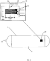
- the present disclosure provides an alternative, cost-effective safety feature incorporating a fill cycle counter with a driver warning and shutdown system 5.
- the system 5 monitors the number of times a hydrogen container 10 is filled, and then takes action at a predetermined termination point.
- a sensor 40 monitors each time the hydrogen container 10 is filled above 90% of the rated pressure or mass. Once the preset life is reached, the disclosed device/method will either disable the valve 12 or refueling mechanism such that fuel supply to the vehicle is shutoff and the container 10 cannot be filled again. This essentially assures the end of life of the container 10.
- a shut-off valve assembly 12 is attached to the wall of container 10.
- the container 10 is placed on-board a vehicle that utilizes hydrogen for fuel.
- a typical container 10 for on-board hydrogen storage is designed to have a rated pressure of about 5000 to 10,000 psi (345 to 690 bar).
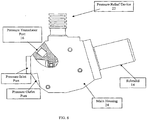
- an exemplary valve assembly 12 comprises an electrical solenoid shut-off valve 14, pressure transducer 16, temperature transducer 18 and a check valve 20.
- the valve 12 may also have a pressure relief device 22 if the internal pressure increase beyond the design pressure.
- Hydrogen is filled in the container 10 through check valve 20 which only allows unidirectional flow, i.e. flow into the container 10. Upon demand from the powertrain, hydrogen flows out of the container 10 through the valve opening.
- a sensor 40 is incorporated to monitor the number of fill cycles to the container 10.
- the sensor 40 is a strain gauge. Any type of gauge or sensor 40 may be utilized to signal that a fill has been made.
- the senor 40 is built into either the container 10 wall or valve 12 to detect each time the container 10 is filled.
- the sensor 40 monitors the number of fill cycles until the number of fill cycles reaches a predetermined termination point. When the number of fill cycles have reached this predetermined termination point, a shut-off device is activated.
- a significant event has occurred.
- the sensor 40 indicates that a fill cycle should be counted. It is also possible to count a number of partial fills as one complete fill event.
- a controller 42 is utilized to count the number of cycles. Once the system has reached the predetermined termination point for the number of fill cycles, the controller 42 will activate a shut-off device 46 to prevent the system from allowing any further fill cycles.
- a vehicle may have an expected utilization of about 250,000 miles (402336km).
- a typical on-board hydrogen storage container 10 has a range of about 200 miles (322km).
- the container 10 would be designed for fill cycles totaling about 1250 cycles.
- 1250 would be the predetermined termination point for the number of cycles for the exemplary hydrogen storage system.
- the shut-off device 46 is activated.
- these numbers are only an illustrative.
- One skilled in the art could design another container utilizing the disclosed safety and shutdown device with various ranges and design parameters.
- the sensor 40 may be a metallic strain gauge 28.
- the metallic strain gauge 28 comprises a very fine wire 36 or, more commonly, metallic foil arranged in a grid pattern 30.
- the grid pattern 30 maximizes the amount of metallic wire or foil 36 subject to strain in the parallel direction.
- the grid 30 is bonded to a thin backing, or carrier 32.
- the grid 30 may be bonded to the carrier 32 utilizing solder tabs 34.
- the carrier 32 is mounted to the container 10 wall. When strain is experienced by the container 10 during a fill cycle, the strain is transferred directly to the strain gauge 28, increasing the length of the grid 30.
- the metallic strain gauge 28 then responds with a linear change in electrical resistance, thereby sensing the fill cycle.
- the sensor 40 may be a fiber optic strain gauge 60.
- a fiber optic strain gauge 60 comprises a fiber optic cable 62 embedded in the wall of the container 10.
- the fiber optic cable 62 includes a Bragg grating 66 enclosed in a glass tube 62.
- the glass tube 62 is attached to the fiber optic 62 cable utilizing adhesives 68.
- a fiber optic Bragg grating 66 is a periodic variation in the index of refraction along a length of optical fiber.
- the sensor 40 measures the strain by shifting the light frequency of the light reflected down the fiber from the Bragg grating 66, which is embedded inside the fiber 62 itself. Fiber optic cables are useful since fiber optics are immune to electrical interference and corrosion.
- the acoustic emission strain gauge comprises a transmitter 70 and receiver 72 mounted to the container 10.
- the acoustic emission signal wave 74 can be used as a medium to detect when a material change has occurred to the container 10; i.e. strain on the container 10.
- the receiver 72 has received this acoustic emission signal wave 74, the system senses that a fill cycle has occurred.
- a flow switch or pressure drop switch is incorporated in the valve housing 24 or thereabouts to count the number of fill cycles.
- a pressure transducer 16 in the valve 12.
- the pressure transducer 16 monitors the pressure in the valve 12. When the valve 12 is under pressure, the pressure transducer 16 is displaced and converts this displacement into an electrical output such as voltage or current. When the pressure transducer 16 emits an electrical voltage, the system counts one fill cycle.
- a moveable membrane is incorporated in the valve body housing 24. While the container is filled with hydrogen, the membrane contacts a switch that counts the number of fill cycles.
- the temperature transducer 18 present in the system is used to monitor the number of fill cycles.
- the system 5 monitors when the temperature of the stored gas increases, as is associated with the filling process. In another implementation, the system 5 monitors and counts the number of times the temperature of the stored gas decreases, as is associated with the discharge process.
- the safety system and shutdown device 5 could be controlled by a number of different controllers.
- the safety and shutdown system is attached to the engine control unit in the vehicle. Signals from the sensor 40 will be processed by the fuel system controller to keep track of the total number of fills.
- the senor 40 or strain gauge may be connected to separate microprocessor attached to the container 10.
- the microprocessor will count the number of fill cycles. Once the number of fills has reached the predetermined termination point, the microprocessor activates a shut-off device 46, rendering the container unusable.
- the controller 42 may be a mechanical counter.
- the mechanical counter may comprise a switch that is activated wherever a fill cycle is completed. The mechanical counter could then disable the system and prevent further use of the hydrogen container 10.
- the controller 42 will de-activate the check valve 20 to prevent further filling of the storage system.
- the system will shut down the check valve and prevent any more fuel from entering the system.
- controller 42 will permanently shut off power to the solenoid valve 14 such that no fuel could be released. This will essentially disable the fuel system and ground the vehicle.
- the controller 42 will cause the pressure transducer 16 to send a spurious "full” signal to the refueling station and/or vehicle on-board refueling control unit such that the container 10 cannot be filled any further due to the "full" indication.
- the shutdown system further comprises a warning device 44 to notify the driver of the vehicle that the container 10 is nearing it predetermined termination point.
- the warning device 44 will indicate to a driver of the vehicle that service is needed, possibly replacement of the container, to continue operation of the vehicle
- hardware and software measures 48 are introduced to render the fill cycle and the shut-off device 46 tamper-proof, in a fashion similar to odometer tamper protection of the present day vehicles. This prevents users of a vehicle from overriding the system, and continuing to use the hydrogen container 10 after the container 10 has realized its full life.
- the various implementations of the present disclosure are applicable to pressurized and liquid hydrogen storage systems, either in the form of compressed gas at generally room temperature, compressed gas at temperatures between room temperature and cryogenic temperatures and gas that is stored by means of physisorption or in the form of chemical hydrides.
Landscapes
- Engineering & Computer Science (AREA)
- Mechanical Engineering (AREA)
- General Engineering & Computer Science (AREA)
- Filling Or Discharging Of Gas Storage Vessels (AREA)
Claims (25)
- Système d'avertissement de sécurité et d'arrêt (5) pour un conteneur de stockage d'hydrogène (10) comprenant :un conteneur de stockage d'hydrogène (10) ;un ensemble vanne (12) fixé au conteneur, l'ensemble vanne ayant un clapet antiretour (20) pour le remplissage du conteneur de stockage d'hydrogène, une vanne électromagnétique (14), un transducteur de pression (16) et un transducteur de température (18) ;un capteur (40) pour surveiller le nombre de cycles de remplissage ; etun dispositif d'arrêt (46) pour désactiver une utilisation ultérieure du système après avoir atteint une limite prédéterminée pour le nombre de cycles de remplissage ;caractérisé en ce que la vanne électromagnétique (14) est située à l'extérieur du conteneur (10).
- Système d'avertissement de sécurité et d'arrêt (5) selon la revendication 1, dans lequel le capteur (40) comprend une jauge de contrainte placée dans le conteneur de stockage d'hydrogène (10).
- Système d'avertissement de sécurité et d'arrêt (5) selon la revendication 1 ou la revendication 2, dans lequel le capteur (40) comprend une jauge de contrainte (60) utilisant des fibres optiques intégrées pour mesurer la contrainte dans le conteneur (10).
- Système d'avertissement de sécurité et d'arrêt (5) selon la revendication 1 ou la revendication 2, dans lequel le capteur comprend une jauge de contrainte métallique (28) dans le conteneur (10) pour mesurer la contrainte.
- Système d'avertissement de sécurité et d'arrêt (5) selon la revendication 1 ou la revendication 2, dans lequel le capteur (40) utilise des émissions acoustiques pour mesurer la contrainte.
- Système d'avertissement de sécurité et d'arrêt (5) selon la revendication 1, dans lequel le capteur (40) est une jauge de contrainte comprenant une membrane dans la vanne activée lors d'un changement de pression dans la vanne.
- Système d'avertissement de sécurité et d'arrêt (5) selon toute revendication précédente, comprenant en outre un système d'avertissement (44) pour avertir un utilisateur d'un véhicule que le système approche la limite prédéterminée.
- Système d'avertissement de sécurité et d'arrêt (5) selon toute revendication précédente, comprenant en outre des mesures logicielles et matérielles (48) pour empêcher d'altérer le système une fois que le système a atteint la limite prédéterminée.
- Système d'avertissement de sécurité et d'arrêt (5) selon toute revendication précédente, dans lequel le cycle de remplissage est compté chaque fois que le conteneur d'hydrogène (10) est rempli au-dessus de 90 % de la pression nominale ou de la masse.
- Système d'avertissement de sécurité et d'arrêt (5) selon toute revendication précédente, dans lequel le dispositif d'arrêt (46) est un contrôleur (42) qui compte le nombre de cycles de remplissage.
- Système d'avertissement de sécurité et d'arrêt (5) selon toute revendication précédente, dans lequel le dispositif d'arrêt (46) désactive la vanne électromagnétique (14) pour désactiver la vanne et empêcher une utilisation ultérieure du système après que le nombre de cycles de remplissage a atteint la limite prédéterminée.
- Système d'avertissement de sécurité et d'arrêt (5) selon l'une quelconque des revendications 1 à 10, dans lequel le dispositif d'arrêt (46) désactive le clapet antiretour (20) pour désactiver la vanne et empêcher une utilisation ultérieure du système après que le nombre de cycles de remplissage a atteint la limite prédéterminée.
- Système d'avertissement de sécurité et d'arrêt (5) selon l'une quelconque des revendications 1 à 10, dans lequel le dispositif d'arrêt (46) est un contrôleur qui compte le nombre de fois que la température du gaz stocké augmente, et est associé au procédé de remplissage.
- Système d'avertissement de sécurité et d'arrêt (5) selon l'une quelconque des revendications 1 à 10, dans lequel le dispositif d'arrêt (46) est un contrôleur qui compte le nombre de fois que la température du gaz stocké baisse, et est associé au procédé d'évacuation.
- Système d'avertissement de sécurité et d'arrêt (5) selon toute revendication précédente, dans lequel le système empêche un remplissage ultérieur du conteneur de stockage d'hydrogène (10) après que le nombre de cycles de remplissage a atteint la limite prédéterminée, en envoyant un faux signal indiquant que le système est déjà complètement rempli au contrôleur du poste de remplissage.
- Système d'avertissement de sécurité et d'arrêt (5) selon la revendication 10, dans lequel le contrôleur (42) est un d'une unité de commande de moteur.
- Système d'avertissement de sécurité et d'arrêt (5) selon la revendication 10, dans lequel le contrôleur (42) est un microprocesseur séparé fixé au réservoir.
- Procédé de fourniture d'un système d'avertissement de sécurité et d'arrêt (5) pour un conteneur de stockage d'hydrogène (10) comprenant :la fourniture d'un conteneur de stockage d'hydrogène, d'un ensemble vanne (12) fixé au conteneur, l'ensemble vanne ayant un clapet antiretour (20) pour le remplissage du conteneur de stockage d'hydrogène, d'une vanne électromagnétique (14), d'un transducteur de pression (16) et d'un transducteur de température (18) ;le comptage du nombre de cycles de remplissage utilisant un capteur (40) ; etla désactivation de la vanne et d'une utilisation ultérieure du système après avoir atteint un nombre prédéterminé de cycles de remplissage ;caractérisé en ce que la vanne électromagnétique (14) est située à l'extérieur du conteneur (10).
- Procédé selon la revendication 18, dans lequel le capteur (40) comprend une jauge de contrainte (60) utilisant des fibres optiques intégrées dans le conteneur (10) pour mesurer la contrainte.
- Procédé selon la revendication 18, dans lequel le capteur (40) comprend une jauge de contrainte métallique (28) dans le conteneur (10) pour mesurer la contrainte.
- Procédé selon la revendication 18, dans lequel un système de surveillance des émissions acoustiques est utilisé pour mesurer une contrainte.
- Procédé selon la revendication 18, dans lequel le capteur (40) est un transducteur de pression situé dans la vanne du système.
- Procédé selon l'une quelconque des revendications 18 à 22, comprenant en outre l'avertissement d'un utilisateur d'un véhicule que le système approche le nombre prédéterminé de cycles de remplissage.
- Procédé selon l'une quelconque des revendications 18 à 23, comprenant en outre des mesures logicielles et matérielles (48) pour empêcher d'altérer le système une fois que le système a atteint le nombre prédéterminé de cycles de remplissage.
- Procédé selon l'une quelconque des revendications 18 à 24, comprenant en outre la désactivation du clapet antiretour (20) pour désactiver la vanne et empêcher une utilisation ultérieure du système après que le nombre de cycles de remplissage a atteint le nombre prédéterminé.
Applications Claiming Priority (2)
| Application Number | Priority Date | Filing Date | Title |
|---|---|---|---|
| US75377405P | 2005-12-23 | 2005-12-23 | |
| PCT/US2006/049060 WO2007076026A2 (fr) | 2005-12-23 | 2006-12-21 | Dispositif et procede d'avertissement de securite et d'arret et procede pour conteneurs de stockage d'hydrogene |
Publications (3)
| Publication Number | Publication Date |
|---|---|
| EP1963547A2 EP1963547A2 (fr) | 2008-09-03 |
| EP1963547A4 EP1963547A4 (fr) | 2011-05-04 |
| EP1963547B1 true EP1963547B1 (fr) | 2019-07-03 |
Family
ID=38218671
Family Applications (1)
| Application Number | Title | Priority Date | Filing Date |
|---|---|---|---|
| EP06848046.6A Active EP1963547B1 (fr) | 2005-12-23 | 2006-12-21 | Dispositif et procede d'avertissement de securite et d'arret et procede pour conteneurs de stockage d'hydrogene |
Country Status (5)
| Country | Link |
|---|---|
| US (1) | US7868775B2 (fr) |
| EP (1) | EP1963547B1 (fr) |
| JP (1) | JP2009521655A (fr) |
| CN (1) | CN101365825B (fr) |
| WO (1) | WO2007076026A2 (fr) |
Families Citing this family (31)
| Publication number | Priority date | Publication date | Assignee | Title |
|---|---|---|---|---|
| US20080148853A1 (en) * | 2003-09-22 | 2008-06-26 | Hyeung-Yun Kim | Gas tank having usage monitoring system |
| US20080319688A1 (en) * | 2007-02-26 | 2008-12-25 | Hyeung-Yun Kim | Usage monitoring system of gas tank |
| US8517206B2 (en) * | 2009-05-19 | 2013-08-27 | Quantum Fuel Systems Technologies Worldwide Inc. | High pressure storage vessel |
| US8297126B2 (en) * | 2010-06-09 | 2012-10-30 | GM Global Technology Operations LLC | Integration of strain gauges at inner- and outer liner of a high pressure tank to indicate discharge limit point |
| US20120048750A1 (en) * | 2010-09-01 | 2012-03-01 | Savannah River Nuclear Solutions Llc | Reduced wear component for use in high pressure hydrogen environments |
| JP5409688B2 (ja) * | 2011-04-06 | 2014-02-05 | 本田技研工業株式会社 | 圧力容器 |
| KR101337908B1 (ko) * | 2011-12-01 | 2013-12-09 | 기아자동차주식회사 | 연료전지 자동차의 실시간 탱크 변형 정보를 이용하는 수소 안전 충전 시스템 및 충전 방법 |
| PL2788215T3 (pl) | 2011-12-07 | 2020-06-15 | Agility Fuel Systems Llc | Systemy i sposoby monitorowania i kontrolowania układów paliwowych |
| KR101517552B1 (ko) * | 2013-08-22 | 2015-05-04 | 한국생산기술연구원 | 압력용기 이력관리장치 및 그의 충진방법 |
| KR101498386B1 (ko) * | 2013-10-28 | 2015-03-03 | 서울과학기술대학교 산학협력단 | 광섬유 브래그 격자 센서를 이용한 극저온 유체 저장 탱크 모니터링 시스템 |
| FR3033190B1 (fr) * | 2015-02-26 | 2017-10-13 | Inergy Automotive Systems Res (Societe Anonyme) | Jaugeage de systeme de stockage d'ammoniac base sur une mesure de la variation d'indice de refraction. |
| JP2017081326A (ja) * | 2015-10-27 | 2017-05-18 | スズキ株式会社 | 燃料電池二輪車の配管継手配置構造 |
| EP3211289B1 (fr) | 2016-02-26 | 2021-12-15 | Nel Hydrogen A/S | Systeme de communication/contrôle pour une station service de hydrogene |
| EP3211288B1 (fr) * | 2016-02-26 | 2023-10-25 | Nel Hydrogen A/S | Systeme de controle pour une station service de hydrogene |
| DE102017208537A1 (de) * | 2017-05-19 | 2018-11-22 | Bayerische Motoren Werke Aktiengesellschaft | Druckbehälter mit Datenlogger |
| FR3073921B1 (fr) * | 2017-11-21 | 2021-10-08 | Air Liquide | Recipient de fluide sous pression a jauge de contrainte et moyens de communication a |
| DE102018104327B4 (de) * | 2018-02-26 | 2021-11-04 | Ika - Werke Gmbh & Co. Kg | Kalorimeter |
| DE202018101670U1 (de) * | 2018-03-26 | 2019-07-02 | Frauenthal Automotive Service Gmbh | Überwachungssystem für einen Gasdruckbehälter |
| EP3671007A1 (fr) * | 2018-12-17 | 2020-06-24 | Linde GmbH | Dispositif et procédé de détermination d'un contenu d'une unité de stockage |
| FR3092897B1 (fr) * | 2019-02-15 | 2021-01-15 | Air Liquide | Procédé de collage d’une jauge de contrainte sur un objet, tel un récipient de gaz |
| CN111207288A (zh) * | 2020-01-13 | 2020-05-29 | 山东特爱纳米科技有限公司 | 一种多功能储氢容器及应用 |
| CN112879794A (zh) * | 2021-03-16 | 2021-06-01 | 永安行科技股份有限公司 | 一种低压安全储氢器及氢燃料电动自行车 |
| DE102020115313A1 (de) * | 2020-06-09 | 2021-12-09 | Bayerische Motoren Werke Aktiengesellschaft | Verfahren und Vorrichtung zur Überwachung eines Druckbehältersystems |
| CN112050091A (zh) * | 2020-09-08 | 2020-12-08 | 上海氢枫能源技术有限公司 | 加氢机正常运行的保护方法 |
| CN114623374A (zh) * | 2020-12-14 | 2022-06-14 | 郑州宇通客车股份有限公司 | 一种车载氢气瓶的加氢方法及系统 |
| CN112550081A (zh) * | 2020-12-17 | 2021-03-26 | 中通客车控股股份有限公司 | 一种气瓶形变监测控制装置及方法、电池汽车 |
| DE102021130123B4 (de) | 2021-11-18 | 2023-06-29 | Mahnken & Partner GmbH | Druckbehälter, insbesondere für Wasserstoff, und Druckspeichersysteme sowie deren Herstellung |
| US20260031372A1 (en) * | 2022-03-30 | 2026-01-29 | Tatsumi Ryoki Co., Ltd | Electric power supply system |
| JP7743819B2 (ja) * | 2022-07-21 | 2025-09-25 | トヨタ自動車株式会社 | 高圧タンク |
| CN115547014B (zh) * | 2022-09-26 | 2026-03-03 | 中通客车股份有限公司 | 一种多瓶组车载储氢智能监测预警系统及方法 |
| GB2633823A (en) * | 2023-09-22 | 2025-03-26 | Phinia Delphi Luxembourg Sarl | Method for managing pressure within a gas tank |
Citations (1)
| Publication number | Priority date | Publication date | Assignee | Title |
|---|---|---|---|---|
| US20050103382A1 (en) * | 2003-11-18 | 2005-05-19 | Carter Stephen A. | Flow control system for a valve |
Family Cites Families (33)
| Publication number | Priority date | Publication date | Assignee | Title |
|---|---|---|---|---|
| US4570822A (en) * | 1981-06-19 | 1986-02-18 | Cozzoli Machine Co. | Computer operated filling system |
| US4703174A (en) * | 1984-03-02 | 1987-10-27 | Fiberdynamics, Inc. | Fiberoptic temperature/pressure sensor system |
| US5000664A (en) * | 1989-06-07 | 1991-03-19 | Abbott Laboratories | Apparatus and method to test for valve leakage in a pump assembly |
| US5207251A (en) * | 1990-12-05 | 1993-05-04 | Dipiero, Inc. | Liquid level sensing method and apparatus |
| JP3287037B2 (ja) * | 1992-12-25 | 2002-05-27 | トヨタ自動車株式会社 | エバポパージシステムの故障診断装置 |
| JPH05288300A (ja) * | 1992-04-08 | 1993-11-02 | Tatsuno Co Ltd | 圧縮天然ガス充填装置 |
| US5303842A (en) * | 1992-07-23 | 1994-04-19 | Tammie Harp | Fuel meter and theft prevention device |
| US5427160A (en) * | 1993-10-12 | 1995-06-27 | Trw Vehicle Safety Systems Inc. | Method of filling a container |
| US5522428A (en) * | 1994-08-29 | 1996-06-04 | Duvall; Paul F. | Natural gas vehicle tank life sensor and control |
| US5589823A (en) * | 1994-12-29 | 1996-12-31 | Lange; Robert | Remote status indicator for holding tanks containing no moving parts |
| JPH08219393A (ja) * | 1995-02-15 | 1996-08-30 | Toray Ind Inc | ガスボンベ |
| JP2633820B2 (ja) * | 1995-06-16 | 1997-07-23 | ボッシュ包装機株式会社 | 液体の圧力充填方法 |
| JPH0968453A (ja) * | 1995-06-23 | 1997-03-11 | Automot Technol Internatl Inc | 外力を受ける陸上車の燃料タンク中の燃料の量を測定する方法および装置 |
| JPH09164860A (ja) * | 1995-12-19 | 1997-06-24 | Mitsubishi Motors Corp | 定速走行装置付き自動変速式自動車 |
| US5701863A (en) * | 1996-09-24 | 1997-12-30 | Caterpillar Inc. | Aqueous fuel emulsion identification system and anti-tampering device for an internal combustion engine |
| CA2280641A1 (fr) * | 1999-08-24 | 2001-02-24 | Veritek Ngv Canada, Corp. | Systeme d'exploitation de bouteilles a gaz |
| US6653005B1 (en) * | 2000-05-10 | 2003-11-25 | University Of Central Florida | Portable hydrogen generator-fuel cell apparatus |
| JP2002115798A (ja) * | 2000-10-06 | 2002-04-19 | Neriki:Kk | バルブ装置 |
| JP2002161997A (ja) * | 2000-11-24 | 2002-06-07 | Sony Corp | 水素カートリッジ、水素ガス供給システム及び水素カートリッジの管理方法 |
| JP2002235899A (ja) * | 2001-02-09 | 2002-08-23 | High Pressure Gas Safety Institute Of Japan | 高圧ガス容器監視システム |
| JP2003028393A (ja) * | 2001-07-17 | 2003-01-29 | Honda Motor Co Ltd | ガス燃料車両のガス燃料貯蔵装置 |
| JP4197648B2 (ja) * | 2001-10-18 | 2008-12-17 | シーケーディ株式会社 | パルスショット式流量調整装置とパルスショット式流量調整方法 |
| US6505470B1 (en) * | 2002-02-28 | 2003-01-14 | Chart Inc. | System for detecting overflow of a tank |
| JP4317346B2 (ja) * | 2002-03-15 | 2009-08-19 | 本田技研工業株式会社 | 燃料ガス充填制御装置 |
| JP2004044752A (ja) * | 2002-07-15 | 2004-02-12 | Jfe Steel Kk | 潤滑剤の給油脂状態監視センサ及び給油脂状態監視装置 |
| US7406987B2 (en) * | 2002-09-25 | 2008-08-05 | Taiyo Nippon Sanso Corporation | Apparatus and method for filling fuel |
| US7030770B2 (en) * | 2003-02-28 | 2006-04-18 | Stuart Energy Systems Corporation | Hydrogen storage system and power system incorporating same |
| US6957574B2 (en) * | 2003-05-19 | 2005-10-25 | Weatherford/Lamb, Inc. | Well integrity monitoring system |
| JP2005122425A (ja) * | 2003-10-16 | 2005-05-12 | Denso Corp | 積算走行距離の改竄検出装置 |
| JP4081430B2 (ja) * | 2003-11-19 | 2008-04-23 | 本田技研工業株式会社 | 燃料電池車両 |
| WO2005072229A2 (fr) * | 2004-01-23 | 2005-08-11 | University Of Pittsburgh Of The Commonwealth System Of Higher Education | Composants optiques actifs dans la fibre alimentes par une lumiere dans la fibre |
| US7059364B2 (en) * | 2004-02-12 | 2006-06-13 | Gas Technology Institute | Control method for high-pressure hydrogen vehicle fueling station dispensers |
| JP4321303B2 (ja) * | 2004-02-24 | 2009-08-26 | 株式会社デンソー | プログラム配信システムおよび車載ゲートウェイ装置 |
-
2006
- 2006-12-21 EP EP06848046.6A patent/EP1963547B1/fr active Active
- 2006-12-21 JP JP2008547616A patent/JP2009521655A/ja active Pending
- 2006-12-21 CN CN2006800482559A patent/CN101365825B/zh not_active Expired - Fee Related
- 2006-12-21 WO PCT/US2006/049060 patent/WO2007076026A2/fr not_active Ceased
- 2006-12-21 US US11/614,936 patent/US7868775B2/en active Active
Patent Citations (1)
| Publication number | Priority date | Publication date | Assignee | Title |
|---|---|---|---|---|
| US20050103382A1 (en) * | 2003-11-18 | 2005-05-19 | Carter Stephen A. | Flow control system for a valve |
Also Published As
| Publication number | Publication date |
|---|---|
| EP1963547A4 (fr) | 2011-05-04 |
| CN101365825B (zh) | 2013-06-19 |
| EP1963547A2 (fr) | 2008-09-03 |
| JP2009521655A (ja) | 2009-06-04 |
| WO2007076026A2 (fr) | 2007-07-05 |
| US20070159345A1 (en) | 2007-07-12 |
| WO2007076026A3 (fr) | 2008-06-26 |
| US7868775B2 (en) | 2011-01-11 |
| CN101365825A (zh) | 2009-02-11 |
Similar Documents
| Publication | Publication Date | Title |
|---|---|---|
| EP1963547B1 (fr) | Dispositif et procede d'avertissement de securite et d'arret et procede pour conteneurs de stockage d'hydrogene | |
| KR101337908B1 (ko) | 연료전지 자동차의 실시간 탱크 변형 정보를 이용하는 수소 안전 충전 시스템 및 충전 방법 | |
| EP2788215B1 (fr) | Systèmes et procédés de surveillance et de contrôle de systèmes de carburant | |
| US9109750B2 (en) | Gas filling method, gas filling system, gas station and mobile unit | |
| US6502461B2 (en) | Method and apparatus for monitoring liquid level in a container | |
| RU2012139662A (ru) | Система управления для безопасной заправки топливом транспортных средств | |
| US20160017823A1 (en) | Systems and methods for regulating fuel systems | |
| EP2062850A2 (fr) | Appareil de stockage et libération de gaz hydrogène comprimé dans des réseaux microcylindriques et système de remplissage de réseaux microcylindriques | |
| EP2287458A2 (fr) | Procédé pour détecter au moins un réservoir de gaz haute pression défaillant | |
| US8857167B2 (en) | Integral accumulator/reservoir system | |
| US20110155278A1 (en) | Cng time fill system and method with safe fill technology | |
| WO1999040553A1 (fr) | Dispositif d'alarme pour detecter la quantite de gaz a l'interieur d'un recipient sous pression | |
| US8927171B2 (en) | Method for preventing pressure in vessels from dropping below minimum allowable pressure | |
| US9166237B2 (en) | Passive temperature supervision device for a compressed gas fuel tank | |
| EP3128222B1 (fr) | Dispositif de remplissage de gaz naturel liquéfié | |
| HK1129912A (en) | Safety warning and shutdown device and method for hydrogen storage containers | |
| CN103162089B (zh) | 泄压装置,热激活的泄压装置,以及测试泄压装置的方法 | |
| US11796133B2 (en) | Automatic obstruction device of a circuit for filling one or more tanks with a fluid | |
| CN115698581A (zh) | 用于监控压力容器系统的方法和装置 | |
| CN217422932U (zh) | 一种储氢罐组剩余氢量获取装置及系统 | |
| Rüdiger | Design characteristics and performance of a liquid hydrogen tank system for motor cars | |
| US20080079606A1 (en) | Article and method for monitoring temperature and pressure within a pressurized gas cylinder | |
| KR20150144437A (ko) | 펌프 관리 장치 및 방법 및 이를 포함하는 액화가스 처리 시스템 | |
| CN210687758U (zh) | 一种深冷压力容器用限充装置 | |
| Kuruba et al. | Digital fuel indicators of various automobiles |
Legal Events
| Date | Code | Title | Description |
|---|---|---|---|
| PUAI | Public reference made under article 153(3) epc to a published international application that has entered the european phase |
Free format text: ORIGINAL CODE: 0009012 |
|
| 17P | Request for examination filed |
Effective date: 20080701 |
|
| AK | Designated contracting states |
Kind code of ref document: A2 Designated state(s): AT BE BG CH CY CZ DE DK EE ES FI FR GB GR HU IE IS IT LI LT LU LV MC NL PL PT RO SE SI SK TR |
|
| AX | Request for extension of the european patent |
Extension state: AL BA HR MK RS |
|
| RIN1 | Information on inventor provided before grant (corrected) |
Inventor name: SIROSH, NEEL Inventor name: STAPLES, TONY Inventor name: MILLER, BOB |
|
| A4 | Supplementary search report drawn up and despatched |
Effective date: 20110405 |
|
| RIC1 | Information provided on ipc code assigned before grant |
Ipc: F17C 13/12 20060101ALI20110330BHEP Ipc: C25B 9/00 20060101AFI20080703BHEP |
|
| DAX | Request for extension of the european patent (deleted) | ||
| STAA | Information on the status of an ep patent application or granted ep patent |
Free format text: STATUS: EXAMINATION IS IN PROGRESS |
|
| RAP1 | Party data changed (applicant data changed or rights of an application transferred) |
Owner name: DOUGLAS ACQUISITIONS LLC |
|
| 17Q | First examination report despatched |
Effective date: 20170403 |
|
| RAP1 | Party data changed (applicant data changed or rights of an application transferred) |
Owner name: QUANTUM FUEL SYSTEMS LLC |
|
| GRAP | Despatch of communication of intention to grant a patent |
Free format text: ORIGINAL CODE: EPIDOSNIGR1 |
|
| STAA | Information on the status of an ep patent application or granted ep patent |
Free format text: STATUS: GRANT OF PATENT IS INTENDED |
|
| INTG | Intention to grant announced |
Effective date: 20190122 |
|
| GRAS | Grant fee paid |
Free format text: ORIGINAL CODE: EPIDOSNIGR3 |
|
| GRAA | (expected) grant |
Free format text: ORIGINAL CODE: 0009210 |
|
| STAA | Information on the status of an ep patent application or granted ep patent |
Free format text: STATUS: THE PATENT HAS BEEN GRANTED |
|
| AK | Designated contracting states |
Kind code of ref document: B1 Designated state(s): AT BE BG CH CY CZ DE DK EE ES FI FR GB GR HU IE IS IT LI LT LU LV MC NL PL PT RO SE SI SK TR |
|
| REG | Reference to a national code |
Ref country code: GB Ref legal event code: FG4D |
|
| REG | Reference to a national code |
Ref country code: CH Ref legal event code: EP Ref country code: AT Ref legal event code: REF Ref document number: 1151100 Country of ref document: AT Kind code of ref document: T Effective date: 20190715 |
|
| REG | Reference to a national code |
Ref country code: IE Ref legal event code: FG4D |
|
| REG | Reference to a national code |
Ref country code: DE Ref legal event code: R096 Ref document number: 602006058267 Country of ref document: DE |
|
| REG | Reference to a national code |
Ref country code: NL Ref legal event code: MP Effective date: 20190703 |
|
| REG | Reference to a national code |
Ref country code: LT Ref legal event code: MG4D |
|
| REG | Reference to a national code |
Ref country code: AT Ref legal event code: MK05 Ref document number: 1151100 Country of ref document: AT Kind code of ref document: T Effective date: 20190703 |
|
| PG25 | Lapsed in a contracting state [announced via postgrant information from national office to epo] |
Ref country code: SE Free format text: LAPSE BECAUSE OF FAILURE TO SUBMIT A TRANSLATION OF THE DESCRIPTION OR TO PAY THE FEE WITHIN THE PRESCRIBED TIME-LIMIT Effective date: 20190703 Ref country code: NL Free format text: LAPSE BECAUSE OF FAILURE TO SUBMIT A TRANSLATION OF THE DESCRIPTION OR TO PAY THE FEE WITHIN THE PRESCRIBED TIME-LIMIT Effective date: 20190703 Ref country code: BG Free format text: LAPSE BECAUSE OF FAILURE TO SUBMIT A TRANSLATION OF THE DESCRIPTION OR TO PAY THE FEE WITHIN THE PRESCRIBED TIME-LIMIT Effective date: 20191003 Ref country code: CZ Free format text: LAPSE BECAUSE OF FAILURE TO SUBMIT A TRANSLATION OF THE DESCRIPTION OR TO PAY THE FEE WITHIN THE PRESCRIBED TIME-LIMIT Effective date: 20190703 Ref country code: LT Free format text: LAPSE BECAUSE OF FAILURE TO SUBMIT A TRANSLATION OF THE DESCRIPTION OR TO PAY THE FEE WITHIN THE PRESCRIBED TIME-LIMIT Effective date: 20190703 Ref country code: FI Free format text: LAPSE BECAUSE OF FAILURE TO SUBMIT A TRANSLATION OF THE DESCRIPTION OR TO PAY THE FEE WITHIN THE PRESCRIBED TIME-LIMIT Effective date: 20190703 Ref country code: PT Free format text: LAPSE BECAUSE OF FAILURE TO SUBMIT A TRANSLATION OF THE DESCRIPTION OR TO PAY THE FEE WITHIN THE PRESCRIBED TIME-LIMIT Effective date: 20191104 Ref country code: AT Free format text: LAPSE BECAUSE OF FAILURE TO SUBMIT A TRANSLATION OF THE DESCRIPTION OR TO PAY THE FEE WITHIN THE PRESCRIBED TIME-LIMIT Effective date: 20190703 |
|
| PG25 | Lapsed in a contracting state [announced via postgrant information from national office to epo] |
Ref country code: ES Free format text: LAPSE BECAUSE OF FAILURE TO SUBMIT A TRANSLATION OF THE DESCRIPTION OR TO PAY THE FEE WITHIN THE PRESCRIBED TIME-LIMIT Effective date: 20190703 Ref country code: IS Free format text: LAPSE BECAUSE OF FAILURE TO SUBMIT A TRANSLATION OF THE DESCRIPTION OR TO PAY THE FEE WITHIN THE PRESCRIBED TIME-LIMIT Effective date: 20191103 Ref country code: LV Free format text: LAPSE BECAUSE OF FAILURE TO SUBMIT A TRANSLATION OF THE DESCRIPTION OR TO PAY THE FEE WITHIN THE PRESCRIBED TIME-LIMIT Effective date: 20190703 Ref country code: GR Free format text: LAPSE BECAUSE OF FAILURE TO SUBMIT A TRANSLATION OF THE DESCRIPTION OR TO PAY THE FEE WITHIN THE PRESCRIBED TIME-LIMIT Effective date: 20191004 |
|
| PG25 | Lapsed in a contracting state [announced via postgrant information from national office to epo] |
Ref country code: TR Free format text: LAPSE BECAUSE OF FAILURE TO SUBMIT A TRANSLATION OF THE DESCRIPTION OR TO PAY THE FEE WITHIN THE PRESCRIBED TIME-LIMIT Effective date: 20190703 |
|
| PG25 | Lapsed in a contracting state [announced via postgrant information from national office to epo] |
Ref country code: IT Free format text: LAPSE BECAUSE OF FAILURE TO SUBMIT A TRANSLATION OF THE DESCRIPTION OR TO PAY THE FEE WITHIN THE PRESCRIBED TIME-LIMIT Effective date: 20190703 Ref country code: RO Free format text: LAPSE BECAUSE OF FAILURE TO SUBMIT A TRANSLATION OF THE DESCRIPTION OR TO PAY THE FEE WITHIN THE PRESCRIBED TIME-LIMIT Effective date: 20190703 Ref country code: EE Free format text: LAPSE BECAUSE OF FAILURE TO SUBMIT A TRANSLATION OF THE DESCRIPTION OR TO PAY THE FEE WITHIN THE PRESCRIBED TIME-LIMIT Effective date: 20190703 Ref country code: PL Free format text: LAPSE BECAUSE OF FAILURE TO SUBMIT A TRANSLATION OF THE DESCRIPTION OR TO PAY THE FEE WITHIN THE PRESCRIBED TIME-LIMIT Effective date: 20190703 Ref country code: DK Free format text: LAPSE BECAUSE OF FAILURE TO SUBMIT A TRANSLATION OF THE DESCRIPTION OR TO PAY THE FEE WITHIN THE PRESCRIBED TIME-LIMIT Effective date: 20190703 |
|
| PG25 | Lapsed in a contracting state [announced via postgrant information from national office to epo] |
Ref country code: SK Free format text: LAPSE BECAUSE OF FAILURE TO SUBMIT A TRANSLATION OF THE DESCRIPTION OR TO PAY THE FEE WITHIN THE PRESCRIBED TIME-LIMIT Effective date: 20190703 Ref country code: IS Free format text: LAPSE BECAUSE OF FAILURE TO SUBMIT A TRANSLATION OF THE DESCRIPTION OR TO PAY THE FEE WITHIN THE PRESCRIBED TIME-LIMIT Effective date: 20200224 |
|
| REG | Reference to a national code |
Ref country code: DE Ref legal event code: R097 Ref document number: 602006058267 Country of ref document: DE |
|
| PLBE | No opposition filed within time limit |
Free format text: ORIGINAL CODE: 0009261 |
|
| STAA | Information on the status of an ep patent application or granted ep patent |
Free format text: STATUS: NO OPPOSITION FILED WITHIN TIME LIMIT |
|
| PG2D | Information on lapse in contracting state deleted |
Ref country code: IS |
|
| REG | Reference to a national code |
Ref country code: CH Ref legal event code: PL |
|
| 26N | No opposition filed |
Effective date: 20200603 |
|
| REG | Reference to a national code |
Ref country code: BE Ref legal event code: MM Effective date: 20191231 |
|
| PG25 | Lapsed in a contracting state [announced via postgrant information from national office to epo] |
Ref country code: MC Free format text: LAPSE BECAUSE OF FAILURE TO SUBMIT A TRANSLATION OF THE DESCRIPTION OR TO PAY THE FEE WITHIN THE PRESCRIBED TIME-LIMIT Effective date: 20190703 Ref country code: SI Free format text: LAPSE BECAUSE OF FAILURE TO SUBMIT A TRANSLATION OF THE DESCRIPTION OR TO PAY THE FEE WITHIN THE PRESCRIBED TIME-LIMIT Effective date: 20190703 |
|
| PG25 | Lapsed in a contracting state [announced via postgrant information from national office to epo] |
Ref country code: LU Free format text: LAPSE BECAUSE OF NON-PAYMENT OF DUE FEES Effective date: 20191221 Ref country code: IE Free format text: LAPSE BECAUSE OF NON-PAYMENT OF DUE FEES Effective date: 20191221 |
|
| PG25 | Lapsed in a contracting state [announced via postgrant information from national office to epo] |
Ref country code: BE Free format text: LAPSE BECAUSE OF NON-PAYMENT OF DUE FEES Effective date: 20191231 Ref country code: CH Free format text: LAPSE BECAUSE OF NON-PAYMENT OF DUE FEES Effective date: 20191231 Ref country code: LI Free format text: LAPSE BECAUSE OF NON-PAYMENT OF DUE FEES Effective date: 20191231 |
|
| PG25 | Lapsed in a contracting state [announced via postgrant information from national office to epo] |
Ref country code: CY Free format text: LAPSE BECAUSE OF FAILURE TO SUBMIT A TRANSLATION OF THE DESCRIPTION OR TO PAY THE FEE WITHIN THE PRESCRIBED TIME-LIMIT Effective date: 20190703 |
|
| PG25 | Lapsed in a contracting state [announced via postgrant information from national office to epo] |
Ref country code: HU Free format text: LAPSE BECAUSE OF FAILURE TO SUBMIT A TRANSLATION OF THE DESCRIPTION OR TO PAY THE FEE WITHIN THE PRESCRIBED TIME-LIMIT; INVALID AB INITIO Effective date: 20061221 |
|
| PGFP | Annual fee paid to national office [announced via postgrant information from national office to epo] |
Ref country code: GB Payment date: 20251229 Year of fee payment: 20 |
|
| PGFP | Annual fee paid to national office [announced via postgrant information from national office to epo] |
Ref country code: FR Payment date: 20251226 Year of fee payment: 20 |
|
| PGFP | Annual fee paid to national office [announced via postgrant information from national office to epo] |
Ref country code: DE Payment date: 20251229 Year of fee payment: 20 |