EP1963633B1 - Systeme d'echappement pour moteur a combustion interne - Google Patents
Systeme d'echappement pour moteur a combustion interne Download PDFInfo
- Publication number
- EP1963633B1 EP1963633B1 EP06831661A EP06831661A EP1963633B1 EP 1963633 B1 EP1963633 B1 EP 1963633B1 EP 06831661 A EP06831661 A EP 06831661A EP 06831661 A EP06831661 A EP 06831661A EP 1963633 B1 EP1963633 B1 EP 1963633B1
- Authority
- EP
- European Patent Office
- Prior art keywords
- catalytic converter
- exhaust passage
- exhaust
- exhaust gas
- control valve
- Prior art date
- Legal status (The legal status is an assumption and is not a legal conclusion. Google has not performed a legal analysis and makes no representation as to the accuracy of the status listed.)
- Expired - Fee Related
Links
Images


Classifications
-
- F—MECHANICAL ENGINEERING; LIGHTING; HEATING; WEAPONS; BLASTING
- F01—MACHINES OR ENGINES IN GENERAL; ENGINE PLANTS IN GENERAL; STEAM ENGINES
- F01N—GAS-FLOW SILENCERS OR EXHAUST APPARATUS FOR MACHINES OR ENGINES IN GENERAL; GAS-FLOW SILENCERS OR EXHAUST APPARATUS FOR INTERNAL-COMBUSTION ENGINES
- F01N3/00—Exhaust or silencing apparatus having means for purifying, rendering innocuous, or otherwise treating exhaust
- F01N3/08—Exhaust or silencing apparatus having means for purifying, rendering innocuous, or otherwise treating exhaust for rendering innocuous
- F01N3/10—Exhaust or silencing apparatus having means for purifying, rendering innocuous, or otherwise treating exhaust for rendering innocuous by thermal or catalytic conversion of noxious components of exhaust
- F01N3/18—Exhaust or silencing apparatus having means for purifying, rendering innocuous, or otherwise treating exhaust for rendering innocuous by thermal or catalytic conversion of noxious components of exhaust characterised by methods of operation; Control
- F01N3/20—Exhaust or silencing apparatus having means for purifying, rendering innocuous, or otherwise treating exhaust for rendering innocuous by thermal or catalytic conversion of noxious components of exhaust characterised by methods of operation; Control specially adapted for catalytic conversion
- F01N3/2006—Periodically heating or cooling catalytic reactors, e.g. at cold starting or overheating
-
- F—MECHANICAL ENGINEERING; LIGHTING; HEATING; WEAPONS; BLASTING
- F01—MACHINES OR ENGINES IN GENERAL; ENGINE PLANTS IN GENERAL; STEAM ENGINES
- F01N—GAS-FLOW SILENCERS OR EXHAUST APPARATUS FOR MACHINES OR ENGINES IN GENERAL; GAS-FLOW SILENCERS OR EXHAUST APPARATUS FOR INTERNAL-COMBUSTION ENGINES
- F01N13/00—Exhaust or silencing apparatus characterised by constructional features
- F01N13/04—Exhaust or silencing apparatus characterised by constructional features having two or more silencers in parallel, e.g. having interconnections for multi-cylinder engines
-
- F—MECHANICAL ENGINEERING; LIGHTING; HEATING; WEAPONS; BLASTING
- F01—MACHINES OR ENGINES IN GENERAL; ENGINE PLANTS IN GENERAL; STEAM ENGINES
- F01N—GAS-FLOW SILENCERS OR EXHAUST APPARATUS FOR MACHINES OR ENGINES IN GENERAL; GAS-FLOW SILENCERS OR EXHAUST APPARATUS FOR INTERNAL-COMBUSTION ENGINES
- F01N3/00—Exhaust or silencing apparatus having means for purifying, rendering innocuous, or otherwise treating exhaust
- F01N3/08—Exhaust or silencing apparatus having means for purifying, rendering innocuous, or otherwise treating exhaust for rendering innocuous
- F01N3/10—Exhaust or silencing apparatus having means for purifying, rendering innocuous, or otherwise treating exhaust for rendering innocuous by thermal or catalytic conversion of noxious components of exhaust
- F01N3/18—Exhaust or silencing apparatus having means for purifying, rendering innocuous, or otherwise treating exhaust for rendering innocuous by thermal or catalytic conversion of noxious components of exhaust characterised by methods of operation; Control
- F01N3/20—Exhaust or silencing apparatus having means for purifying, rendering innocuous, or otherwise treating exhaust for rendering innocuous by thermal or catalytic conversion of noxious components of exhaust characterised by methods of operation; Control specially adapted for catalytic conversion
- F01N3/2053—By-passing catalytic reactors, e.g. to prevent overheating
-
- F—MECHANICAL ENGINEERING; LIGHTING; HEATING; WEAPONS; BLASTING
- F01—MACHINES OR ENGINES IN GENERAL; ENGINE PLANTS IN GENERAL; STEAM ENGINES
- F01N—GAS-FLOW SILENCERS OR EXHAUST APPARATUS FOR MACHINES OR ENGINES IN GENERAL; GAS-FLOW SILENCERS OR EXHAUST APPARATUS FOR INTERNAL-COMBUSTION ENGINES
- F01N2410/00—By-passing, at least partially, exhaust from inlet to outlet of apparatus, to atmosphere or to other device
- F01N2410/06—By-passing, at least partially, exhaust from inlet to outlet of apparatus, to atmosphere or to other device at cold starting
-
- Y—GENERAL TAGGING OF NEW TECHNOLOGICAL DEVELOPMENTS; GENERAL TAGGING OF CROSS-SECTIONAL TECHNOLOGIES SPANNING OVER SEVERAL SECTIONS OF THE IPC; TECHNICAL SUBJECTS COVERED BY FORMER USPC CROSS-REFERENCE ART COLLECTIONS [XRACs] AND DIGESTS
- Y02—TECHNOLOGIES OR APPLICATIONS FOR MITIGATION OR ADAPTATION AGAINST CLIMATE CHANGE
- Y02T—CLIMATE CHANGE MITIGATION TECHNOLOGIES RELATED TO TRANSPORTATION
- Y02T10/00—Road transport of goods or passengers
- Y02T10/10—Internal combustion engine [ICE] based vehicles
- Y02T10/12—Improving ICE efficiencies
Definitions
- the invention relates to an exhaust system of an internal combustion engine.
- all of the cylinders are divided into two cylinder groups, each of which is provided with an exhaust manifold, and an exhaust passage is provided for each of the cylinder groups such that the exhaust passage extends from the corresponding exhaust manifold to an exhaust merging point at which streams of exhaust gas from the respective exhaust passages join together.
- control valves are controlled so that the exhaust gas always passes both catalyst either directly through the respective exhaust pipe or through the respective bypass.
- the control valve is used as a wastegate valve of the turbocharger, and the control valve is closed during low-load engine operation in which a small amount of exhaust gas is produced, so that the exhaust gas of all of the cylinders passes the turbine.
- the control valve is opened so that the exhaust gas of the other cylinder group passes the other exhaust passage, and only the exhaust gas of the above-indicated one cylinder group passes the turbine. In this manner, the boost pressure established by the turbocharger is constantly controlled to a set value or its vicinity.
- the object of the invention is to provide an exhaust system of an internal combustion engine, in which exhaust gas is appropriately purified even if a catalytic converter disposed downstream of a turbine deteriorates during a fuel-supply cutoff period.
- the exhaust gas of all of the cylinders mainly passes the first catalytic converter disposed in the first exhaust passage. Accordingly, if the temperature of the first catalytic converter is high, the first catalytic converter may deteriorate due to a large amount of oxygen contained in the exhaust gas.
- the second catalytic converter is disposed in the second exhaust passage. Therefore, during the fuel-supply cutoff period, almost no exhaust gas containing a large amount of oxygen passes the second catalytic converter. As a result, deterioration of the second catalytic converter is suppressed, and the exhaust gas can be purified by the second catalytic converter.
- the temperatures of the first catalytic converter and the second catalytic converter may be measured or estimated. If the temperature of the second catalytic converter is lower than that of the first catalytic converter, the opening amounts of the control valves disposed in the first exhaust passage and the second exhaust passage may be controlled so that the exhaust gas of all of the cylinders mainly passes the second catalytic converter.
- the exhaust gas containing a large amount of oxygen passes the first catalytic converter during the fuel-supply cutoff period, which suppresses deterioration of the first catalytic converter.
- the temperature of the second catalyst is unlikely to be high because the temperature of the second catalytic converter is lower than that of the first converter at this time. Accordingly, deterioration of the second catalytic converter is suppressed.
- the exhaust gas can be appropriately purified by using the two catalytic converters.
- the temperature of the second catalytic converter may be measured or estimated. If the temperature of the second catalytic converter is lower than a predetermined temperature, the opening amounts of the control valves disposed in the first exhaust passage and the second exhaust passage may be controlled so that the exhaust gas of all of the cylinders mainly passes the second catalytic converter.
- the exhaust gas containing a large amount of oxygen passes the first catalytic converter during the fuel-supply cutoff period, which suppresses deterioration of the first catalytic converter.
- the temperature of the second catalyst is lower than the predetermined temperature. Accordingly, deterioration of the second catalytic converter is suppressed. As a result, the exhaust gas can be appropriately purified by using the two catalytic converters.
- control valve disposed in the first exhaust passage may be controlled to be fully closed, and the control valve disposed in the second exhaust passage may be controlled to be fully opened.
- FIG. 1 is the schematic view showing an exhaust system of an internal combustion engine according to one embodiment of the invention.
- the internal combustion engine in the form of a V-type engine includes a first bank 1a and a second bank 1b, and a first exhaust manifold 2a and a second exhaust manifold 2b are connected to the first bank 1a and the second bank 1b, respectively.
- a first exhaust passage 3a is connected to the first exhaust manifold 2a, and a second exhaust passage 3b is connected to the second exhaust manifold 2b.
- the first exhaust passage 3a and the second exhaust passage 3b join together at an exhaust merging point 4, and a main catalytic converter 5 is disposed downstream of the exhaust merging point 4.
- the V-type engine mainly operates at the stoichiometric air/fuel ratio.
- a three-way catalytic converter is selected as the main catalytic converter 5.
- the main catalytic converter 5 is relatively large in size, but this does not cause a problem in terms of vehicle installation efficiency since the converter 5 is mounted under the floor of the vehicle.
- the main catalytic converter 5 favorably purifies a large amount of exhaust gas emitted from respective cylinders during high-load operation of the engine.
- the exhaust gas emitted from the respective cylinders during low-load engine operation has a relatively low temperature, and its temperature is further reduced by the time the exhaust gas flows into the main catalytic converter 5. In this case, therefore, the main catalytic converter 5 cannot be kept at a catalyst activation temperature or its operating temperature, resulting in insufficient purification of the exhaust gas.
- a first auxiliary catalytic converter 6a acting as a three-way catalytic converter is mounted near the engine body in the first exhaust passage 3a
- a second auxiliary catalytic converter 6b is mounted near the engine body in the second exhaust passage 3b.
- the first exhaust passage 3a and the second exhaust passage 3b communicate with each other via a connecting pipe 7 that connects a junction point 7a of the passage 3a with a junction point 7b of the passage 3b.
- a turbine 8 of a turbocharger is disposed in the first exhaust passage 3a between the junction point 7a and the first auxiliary catalytic converter 6a.
- a first control valve 9a is disposed in the first exhaust passage 3a downstream of the first auxiliary catalytic converter 6a. The first control valve 9a adjusts the amount of exhaust gas passing through the first exhaust passage 3a such that the lower limit of the exhaust gas amount is equal to zero, and may be disposed anywhere in the first exhaust passage 3a provided that it is located downstream of the junction point 7a.
- a second control valve 9b is disposed in the second exhaust passage 3b downstream of the second auxiliary catalytic converter 6b.
- the second control valve 9b adjusts the amount of exhaust gas passing through the second exhaust passage 3b such that the lower limit of the exhaust gas amount is equal to zero, and may be disposed anywhere in the second exhaust passage 3b provided that it is located downstream of the junction point 7b.
- the opening amounts of the first control valve 9a and second control valve 9b are controlled by a controller 10 as shown in FIG. 1 .
- a compressor (not shown) of the turbocharger coupled to the turbine 8 is disposed upstream of a throttle valve of an engine intake system, and performs supercharging.
- the opening amounts of the first control valve 9a and second control valve 9b By controlling the opening amounts of the first control valve 9a and second control valve 9b, the amount of exhaust gas passing the turbine 8 of the first exhaust passage 3a can be controlled as desired, namely, can be changed from a condition in which no exhaust gas passes the turbine 8 (which condition is established by fully closing the first control valve 9a and fully opening the second control valve 9b) to a condition in which exhaust gas of all of the cylinders passes the turbine 8 (which condition is established by fully opening the first control valve 9a and fully closing the second control valve 9b).
- the boost pressure can be controlled depending upon the engine operating states by changing the amount of exhaust gas passing the turbine 8, even in the absence of a wastegate passage that is generally provided for bypassing the turbine 8.
- a fuel-supply cutoff operation is usually performed to save fuel.
- air is emitted, as it is, from the respective cylinders as the exhaust gas, and, therefore, the exhaust gas contains a large amount of oxygen.
- the temperature of the main catalytic converter 5 does not become considerably high, because the main catalytic converter 5 is relatively distant from the engine body.
- the temperatures of the first auxiliary catalytic converter 6a and second auxiliary catalytic converter 6b may become considerably high (800 °C or higher), because the first auxiliary catalytic converter 6a and second auxiliary catalytic converter 6b are disposed near the engine body.
- the exhaust gas containing a large amount of oxygen emitted during the fuel-supply cutoff period flows into the first auxiliary catalytic converter 6a or second auxiliary catalytic converter 6b, catalysts, formed of noble metal, usually carried on the catalytic converters, undergo sintering and, consequently, deteriorate. If both the first auxiliary catalytic converter 6a and second auxiliary catalytic converter 6b deteriorate due to such sintering, the exhaust gas cannot be appropriately purified when the engine load is low or when the engine is started.
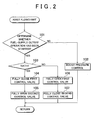
- the controller 10 controls the opening amounts of the first control valve 9a and the second control valve 9b according to the routine of the first flowchart shown in FIG. 2 to prevent deterioration of both the first auxiliary catalytic converter 6a and second auxiliary catalytic converter 6b.
- step 101 it is determined whether the fuel-supply cutoff operation has been started. If a negative determination is made in step 101, in step 102, the controller 10 controls the opening amounts of the first control valve 9a and the second control valve 9b based on the amount of exhaust gas emitted from the respective cylinders in the current engine operating state. Thus, the amount of exhaust gas passing the turbine 8 disposed in the first exhaust passage 3a is controlled to achieve a desired boost pressure.
- the second control valve 9b may be controlled to be fully opened.
- the amount of exhaust gas passing the turbine 8 increases with decreases in the opening amount of the second control valve 9a.
- the first control valve 9a may be controlled to be fully opened.
- step 101 If the fuel-supply cutoff operation has been started and, therefore, an affirmative determination is made in step 101, in step 103, the temperature T1 of the first auxiliary catalytic converter 6a and the temperature T2 of the second auxiliary catalytic converter 6b are measured or estimated, and it is determined whether the temperature T2 of the second auxiliary catalytic converter 6b is lower than the temperature T1 of the first auxiliary catalytic converter 6a.
- the temperatures T1 and T2 are estimated in consideration of the temperature of the exhaust gas based on the engine operation state immediately before the fuel-supply cutoff operation is started, the amounts of exhaust gases that have passed the first auxiliary catalytic converter 6a and the second auxiliary catalytic converter 6b, respectively, and the fact that the temperature of the exhaust gas that will flow into the first auxiliary catalytic converter 6a is decreased when the exhaust gas passes the turbine 8.
- step 103 When an affirmative determination is made in step 103, namely, when the temperature T2 of the second auxiliary catalytic converter 6b is lower than the temperature T1 of the first auxiliary catalytic converter 6a, the first control valve 9a is fully closed in step 104, and the second control valve 9b is fully opened in step 105.
- the exhaust gas in the second bank 1b entirely flows through the second exhaust passage 3b and follows into the second auxiliary catalytic converter 6b.
- the exhaust gas in the first bank 1a entirely flows through the connecting pipe 7 and the second exhaust passage 3b, and flows into the second auxiliary catalytic converter 6b.
- the exhaust gas of all the cylinders passes the second auxiliary catalytic converter 6b.
- the engine load is usually high and, therefore, high boost pressure is required.
- the second control valve 9b is substantially closed, and a large amount of exhaust gas having a high temperature passes the turbine 8.
- the temperature of the first auxiliary catalytic converter 6a disposed downstream of the turbine 8 in the first exhaust passage 3a is usually considerably high.
- the amount of exhaust gas which flows through the second exhaust passage 3b and passes the second auxiliary catalytic converter 6b is small, and the temperature of the second auxiliary catalytic converter 6b is usually relatively low.
- step 103 if an affirmative determination is made in step 103 and, therefore, the exhaust gas of all the cylinders is caused to pass the second auxiliary catalytic converter 6b during the fuel-supply cutoff period, the exhaust gas containing a large amount of oxygen does not pass the first auxiliary catalytic converter 6a having a considerably high temperature. As a result, deterioration of the first auxiliary catalytic converter 6a is suppressed. Meanwhile, the exhaust gas containing a large amount of oxygen passes the second auxiliary catalytic converter 6b. However, there is almost no possibility that the second auxiliary catalytic converter 6b deteriorates because the temperature of the second auxiliary catalytic converter 6b is low.
- step 103 When a negative determination is made in step 103, namely, when the temperature T2 of the second auxiliary catalytic converter 6b is equal to or higher than the temperature T1 of the first auxiliary catalytic converter 6a, the first control valve 9a is fully opened in step 106, and the second control valve 9b is fully closed in step 107.
- the exhaust gas in the first bank 1a entirely flows through the first exhaust passage 3a and flows into the first auxiliary catalytic converter 6a.
- the exhaust gas in the second bank 1b entirely flows through the connecting pipe 7 and the first exhaust passage 3a, and flows into the first auxiliary catalytic converter 6a.
- the exhaust gas of all the cylinders passes the first auxiliary catalytic converter 6a.
- step 103 When a negative determination is made in step 103, in the operating state immediately before the fuel-supply cutoff operation is started, a relatively large amount of exhaust gas passes the second exhaust passage 3b. At this time, the medium-low load engine operation, where the boost pressure need not be as high as that in the high-load engine operation, is performed, and the temperature of the exhaust gas is not as high as that when the engine load is high. Accordingly, the possibility that the temperature T1 of the first auxiliary catalytic converter 6a, which is equal to or lower than the temperature T2 of the second auxiliary catalytic converter 6b, is considerably high is low.
- the first auxiliary catalytic converter 6a Even if the exhaust gas of all the cylinders is caused to pass the first auxiliary catalytic converter 6a, the first auxiliary catalytic converter 6a is unlikely to deteriorate. Also, the second auxiliary catalytic converter 6b, which the exhaust gas does not pass, does not deteriorate. In this manner, deterioration of both the first auxiliary catalytic converter 6a and the second auxiliary catalytic converter 6b is suppressed, which prevents the situation where the exhaust gas cannot be purified when the engine load is low and the engine is started.
- FIG. 3 shows the second flowchart including the routine for controlling the opening amounts of the first control valve 9a and the second control valve 9b to prevent deterioration of both the first auxiliary catalytic converter 6a and the second auxiliary catalytic converter 6b.
- the routine shown in the second flowchart is the same as the routine shown in the first flowchart except the following points.
- step 203 only the temperature T2 of the second auxiliary catalytic converter 6b is measured or estimated, and it is determined whether the temperature T2 is lower than a predetermined temperature T' at which sintering of the catalysts formed of noble metal is not caused even if the air passes the second auxiliary catalytic converter 6b.
- step 203 Only when an affirmative determination is made in step 203, the controller 10 controls the opening amounts of the control valves 9a and 9b so that the first control valve 9a is fully closed in step 204, and the second control valve 9b is fully opened in step 205. As a result, the exhaust gas of all the cylinders passes the second auxiliary catalytic converter 9b.
- deterioration of the second auxiliary catalytic converter 9b is suppressed. Also, because the exhaust gas of all the cylinders passes the second auxiliary catalytic converter 9b during the fuel-supply cutoff period, deterioration of the first auxiliary catalytic converter 6a is not caused. If both the temperature T1 of the first auxiliary catalytic converter 6a and the temperature T2 of the second auxiliary catalytic converter 6b exceed the predetermined temperature T' in the engine operating state immediately before the fuel-supply cutoff operation is started, there is a possibility that the first auxiliary catalytic converter 6a deteriorates. However, the possibility is low. In this manner, deterioration of both the first auxiliary catalytic converter 6a and the second auxiliary catalytic converter 6b is suppressed, which prevents the situation where the exhaust gas cannot be purified when the engine load is low and the engine is started.
- one of the first control valve 9a and the second control valve 9b is fully closed during the fuel-supply cutoff period.
- the first control valve 6a or the second control valve 6b may be slightly opened so that a small amount of exhaust gas passes one of the first auxiliary catalytic converter 6a and the second auxiliary catalytic converter 6b.
- the opening amounts of the first control valve 9a and the second control valve 9b are controlled so that the exhaust gas of all the cylinders mainly passes the other of the first auxiliary catalytic converter 6a and the second auxiliary catalytic converter 6b.
- the temperature of the second auxiliary catalytic converter 6b is measured or estimated when the fuel-supply cutoff operation is started.
- the control is not limited to this.
- both the opening amounts of the first control valve 9a and the second control valve 9b may be controlled so that the first control valve 9a is fully opened and the second control valve 9b is fully closed without measuring or estimating the temperature of the catalytic converter.
- the exhaust gas containing a large amount of oxygen entirely passes the first auxiliary catalytic converter 6a during the fuel-supply cutoff period.
- the exhaust gas can be purified by using at least the second auxiliary catalytic converter 6b when the engine load is low and the engine is started.
- the main catalytic converter 5 is in the form of a three-way catalytic converter in the illustrated embodiment, it may be in the form of a NOx catalytic converter in the case where the internal combustion engine is capable of lean-burn operation.
- the main catalytic converter 5 is preferably a combination of a three-way catalytic converter and a NOx catalytic converter that are arranged in series.
- the invention is not limitedly applied to this type of engine, but may be applied to any type of engine provided that the engine has a plurality of cylinders that can be divided into two groups, each of which is provided with an exhaust manifold.
- the plurality of cylinders may be arranged in series.
- the invention may also be applied to engines having three or more groups of cylinders. In this case, three or more exhaust passages upstream of the exhaust merging point are roughly divided into two groups, so that the invention can be applied to this type of engine.
Landscapes
- Engineering & Computer Science (AREA)
- Chemical & Material Sciences (AREA)
- Chemical Kinetics & Catalysis (AREA)
- Combustion & Propulsion (AREA)
- Mechanical Engineering (AREA)
- General Engineering & Computer Science (AREA)
- Health & Medical Sciences (AREA)
- Toxicology (AREA)
- Exhaust Gas After Treatment (AREA)
- Exhaust Gas Treatment By Means Of Catalyst (AREA)
- Exhaust Silencers (AREA)
Claims (4)
- Système d'échappement d'un moteur à combustion interne ayant une pluralité de cylindres, dans lequel tous les cylindres sont divisés en deux groupes de cylindres et un premier passage d'échappement (3a) et un deuxième passage d'échappement (3b) sont reliés à des collecteurs d'échappement respectifs des deux groupes de cylindres, le premier passage d'échappement (3a) communique avec le deuxième passage d'échappement (3b) par l'intermédiaire d'un premier point de liaison (7a) fourni dans le premier passage d'échappement (3a) et un deuxième point de liaison (7b) fourni dans le deuxième passage d'échappement (3b), une turbine (8) d'un turbocompresseur et un premier convertisseur catalytique (6a), qui est disposé en aval de la turbine (8), sont disposés en aval du premier point de liaison (7a) du premier passage d'échappement (3a), et une soupape de commande (9b) est disposée en aval du deuxième point de liaison (7b) du deuxième passage d'échappement (3b), caractérisé en ce que,
une autre soupape de commande (9a, 9b) est disposée en aval du premier point de liaison (7a) du premier passage d'échappement (3a), un deuxième convertisseur catalytique (6b) est disposé en aval du deuxième point de liaison (7b) du deuxième passage d'échappement (3b), et des proportions d'ouverture des soupapes de commande disposées dans le premier passage d'échappement (3a) et le deuxième passage d'échappement (3b) sont commandées de sorte qu'un gaz d'échappement de tous les cylindres traverse essentiellement l'un du premier convertisseur catalytique (6a) et du deuxième convertisseur catalytique (6b) lorsque l'on arrête l'alimentation en carburant. - Système d'échappement d'un moteur à combustion interne selon la revendication 1, dans lequel;
lorsque l'on arrête l'alimentation en carburant, des températures du premier convertisseur catalytique (6a) et du deuxième convertisseur catalytique (6b) sont mesurées ou estimées, et si la température du deuxième convertisseur catalytique (6b) est inférieure à la température du premier convertisseur catalytique (6a), les proportions d'ouverture des soupapes de commande (9a, 9b) disposées dans le premier passage d'échappement (3a) et le deuxième passage d'échappement (3b) sont commandées de sorte que le gaz d'échappement de tous les cylindres traverse essentiellement le deuxième convertisseur catalytique (6b). - Système d'échappement d'un moteur à combustion interne selon la revendication 1, dans lequel;
lorsque l'on arrête l'alimentation en carburant, une température du deuxième convertisseur catalytique (6b) est mesurée ou estimée, et si la température du deuxième convertisseur catalytique (6b) est inférieure à une température prédéterminée, les proportions d'ouverture des soupapes de commande (9a, 9b) disposées dans le premier passage d'échappement (3a) et le deuxième passage d'échappement (3b) sont commandées de sorte que le gaz d'échappement de tous les cylindres traverse essentiellement le deuxième convertisseur catalytique (6b). - Système d'échappement d'un moteur à combustion interne selon la revendication 2 ou 3, dans lequel
la soupape de commande (9a, 9b) disposée dans le premier passage d'échappement (3a) est commandée de manière à être complètement fermée, et la soupape de commande (9b) disposée dans le deuxième passage d'échappement (3b) est commandée de manière à être complètement ouverte.
Applications Claiming Priority (2)
| Application Number | Priority Date | Filing Date | Title |
|---|---|---|---|
| JP2005354738A JP4333671B2 (ja) | 2005-12-08 | 2005-12-08 | 内燃機関の排気装置 |
| PCT/IB2006/003508 WO2007066211A2 (fr) | 2005-12-08 | 2006-12-07 | Systeme d'echappement pour moteur a combustion interne |
Publications (2)
| Publication Number | Publication Date |
|---|---|
| EP1963633A2 EP1963633A2 (fr) | 2008-09-03 |
| EP1963633B1 true EP1963633B1 (fr) | 2009-08-12 |
Family
ID=38015268
Family Applications (1)
| Application Number | Title | Priority Date | Filing Date |
|---|---|---|---|
| EP06831661A Expired - Fee Related EP1963633B1 (fr) | 2005-12-08 | 2006-12-07 | Systeme d'echappement pour moteur a combustion interne |
Country Status (6)
| Country | Link |
|---|---|
| US (1) | US8099948B2 (fr) |
| EP (1) | EP1963633B1 (fr) |
| JP (1) | JP4333671B2 (fr) |
| CN (1) | CN101326346B (fr) |
| DE (1) | DE602006008503D1 (fr) |
| WO (1) | WO2007066211A2 (fr) |
Families Citing this family (9)
| Publication number | Priority date | Publication date | Assignee | Title |
|---|---|---|---|---|
| DE102004034314A1 (de) * | 2004-07-15 | 2006-02-02 | Volkswagen Ag | Anordnung mit einer Brennkraftmaschine |
| JP4162016B2 (ja) * | 2006-06-08 | 2008-10-08 | トヨタ自動車株式会社 | 内燃機関の排気浄化装置 |
| DE102007032736A1 (de) * | 2007-07-13 | 2009-01-15 | Emitec Gesellschaft Für Emissionstechnologie Mbh | Abgasnachbehandlung vor einem Turbolader |
| DE102009028354B4 (de) * | 2009-08-07 | 2013-05-29 | Mtu Friedrichshafen Gmbh | Gasführungssystem für eine Peripherie einer Brennkraftmaschine zur Führung von Gas der Brennkraftmaschine, Brennkraftsystem und Verfahren zum Betrieb der Brennkraftmaschine |
| WO2012081061A1 (fr) * | 2010-12-17 | 2012-06-21 | トヨタ自動車株式会社 | Dispositif de chauffage d'échappement destiné à un moteur à combustion interne et procédé de commande s'y rapportant |
| DE102011090160B4 (de) * | 2011-12-30 | 2023-02-23 | Dr.Ing.H.C. F. Porsche Ag | Brennkraftmaschine mit einer Anordnung zur Abgas- und Ladeluftführung |
| US9157363B2 (en) * | 2012-08-21 | 2015-10-13 | Ford Global Technologies, Llc | Twin independent boosted I4 engine |
| KR20180126169A (ko) * | 2017-05-17 | 2018-11-27 | 현대자동차주식회사 | 엔진 시스템 |
| US11015511B2 (en) * | 2019-04-04 | 2021-05-25 | Ford Global Technologies, Llc | Methods and system for diagnosing active exhaust valves based on temperature and thermal image data |
Family Cites Families (18)
| Publication number | Priority date | Publication date | Assignee | Title |
|---|---|---|---|---|
| DE2322057A1 (de) * | 1973-05-02 | 1974-11-21 | Porsche Ag | Vorrichtung zum katalytischen nachverbrennen von abgasen einer mehrzylindrigen brennkraftmaschine |
| JPS6060218A (ja) | 1983-09-13 | 1985-04-06 | Mazda Motor Corp | タ−ボ過給機付エンジンの排気装置 |
| JPH01173423A (ja) | 1987-12-28 | 1989-07-10 | Konica Corp | 非磁性粉を含有するバックコート層を設けた磁気記録媒体 |
| JPH06101463A (ja) * | 1992-09-24 | 1994-04-12 | Fuji Heavy Ind Ltd | エンジンの排気ガス浄化装置 |
| JP2827886B2 (ja) | 1994-03-14 | 1998-11-25 | 日産自動車株式会社 | 内燃機関の排気浄化装置 |
| JPH08121153A (ja) | 1994-10-25 | 1996-05-14 | Nissan Motor Co Ltd | 内燃機関の排気浄化装置 |
| DE4444098A1 (de) * | 1994-12-10 | 1996-06-13 | Opel Adam Ag | Brennkraftmaschine mit zwei Zylinderbänken |
| DE19511232A1 (de) * | 1995-03-27 | 1996-10-02 | Abb Management Ag | Verfahren und Vorrichtung zur Registeraufladung einer Brennkraftmaschine |
| JPH10148119A (ja) | 1996-11-20 | 1998-06-02 | Toyota Motor Corp | 内燃機関の排気浄化装置 |
| US6138453A (en) * | 1997-09-19 | 2000-10-31 | Toyota Jidosha Kabushiki Kaisha | Exhaust gas purification device for an internal combustion engine |
| JP2001193445A (ja) | 2000-01-13 | 2001-07-17 | Fuji Heavy Ind Ltd | エンジンの排気装置 |
| JP2001329830A (ja) * | 2000-03-15 | 2001-11-30 | Ibiden Co Ltd | 排気ガス浄化フィルタの再生装置及びフィルタ再生方法、排気ガス浄化フィルタの再生プログラム及びそのプログラムを格納する記録媒体 |
| DE10040516A1 (de) * | 2000-08-18 | 2002-02-28 | Bayerische Motoren Werke Ag | Mehrzylinder-Brennkraftmaschine mit einer Vorrichtung zum Katalysator-Heizen |
| DE10104021B4 (de) * | 2001-01-31 | 2013-04-25 | Daimler Ag | Abgasanlage |
| US6564543B1 (en) * | 2001-04-07 | 2003-05-20 | Ford Global Technologies, Llc | System and method for monitoring a conditioning catalyst |
| JP3966040B2 (ja) * | 2002-03-15 | 2007-08-29 | トヨタ自動車株式会社 | 内燃機関の排気浄化装置 |
| US20040112046A1 (en) * | 2002-12-13 | 2004-06-17 | Prasad Tumati | Thermal management of integrated emission reduction system |
| JP4174767B2 (ja) * | 2003-10-20 | 2008-11-05 | トヨタ自動車株式会社 | 排ガス浄化装置 |
-
2005
- 2005-12-08 JP JP2005354738A patent/JP4333671B2/ja not_active Expired - Fee Related
-
2006
- 2006-12-07 WO PCT/IB2006/003508 patent/WO2007066211A2/fr not_active Ceased
- 2006-12-07 DE DE602006008503T patent/DE602006008503D1/de active Active
- 2006-12-07 CN CN2006800458757A patent/CN101326346B/zh not_active Expired - Fee Related
- 2006-12-07 US US12/085,899 patent/US8099948B2/en not_active Expired - Fee Related
- 2006-12-07 EP EP06831661A patent/EP1963633B1/fr not_active Expired - Fee Related
Also Published As
| Publication number | Publication date |
|---|---|
| US20090038293A1 (en) | 2009-02-12 |
| JP4333671B2 (ja) | 2009-09-16 |
| JP2007154846A (ja) | 2007-06-21 |
| WO2007066211A2 (fr) | 2007-06-14 |
| CN101326346B (zh) | 2011-05-11 |
| US8099948B2 (en) | 2012-01-24 |
| CN101326346A (zh) | 2008-12-17 |
| WO2007066211A3 (fr) | 2007-09-13 |
| EP1963633A2 (fr) | 2008-09-03 |
| DE602006008503D1 (de) | 2009-09-24 |
Similar Documents
| Publication | Publication Date | Title |
|---|---|---|
| US8516814B2 (en) | Exhaust gas purifying apparatus for a turbocharged internal combustion engine | |
| US7753039B2 (en) | Exhaust gas control apparatus of an internal combustion engine | |
| CN102124200B (zh) | 内燃机的控制装置 | |
| US20080209889A1 (en) | Internal Combustion Engine Featuring Exhaust Gas Aftertreatment and Method For the Operation Thereof | |
| JP4057549B2 (ja) | 内燃機関における排気ガス浄化装置 | |
| US9435256B2 (en) | Control apparatus for an internal combustion engine | |
| JP2009024619A (ja) | 内燃機関の排気制御装置 | |
| US10385763B2 (en) | Exhaust system of internal combustion engine | |
| US20090031706A1 (en) | Control apparatus and control method of an internal combustion engine | |
| US8099948B2 (en) | Exhaust system of internal combustion engine | |
| JP4432891B2 (ja) | ターボチャージャ付内燃機関 | |
| EP1957771B1 (fr) | Systeme d'echappement pour moteur a combustion interne | |
| US11300065B2 (en) | Method of controlling temperature of exhaust purification device of internal combustion engine, and internal combustion engine control device | |
| JP2010159672A (ja) | エンジンの排気浄化装置 | |
| JP2008138638A (ja) | 内燃機関の排気還流装置 | |
| JP2007239493A (ja) | 過給機付き内燃機関 | |
| JPH11173138A (ja) | 内燃機関の排気浄化装置 | |
| JP4940927B2 (ja) | ターボチャージャの制御装置 | |
| JP2008138598A (ja) | 内燃機関のegrシステム | |
| JP2006336537A (ja) | 内燃機関の制御装置 | |
| JP2011085108A (ja) | 内燃機関の排気装置 | |
| JP2007291975A (ja) | 内燃機関の排気還流装置 | |
| JP2007303367A (ja) | 内燃機関の排気浄化装置 | |
| JP2006249995A (ja) | 部分気筒運転を行う多気筒エンジンの排気浄化装置 | |
| JP2001152863A (ja) | リーンバーンエンジンの排気温度制御装置 |
Legal Events
| Date | Code | Title | Description |
|---|---|---|---|
| PUAI | Public reference made under article 153(3) epc to a published international application that has entered the european phase |
Free format text: ORIGINAL CODE: 0009012 |
|
| 17P | Request for examination filed |
Effective date: 20080707 |
|
| AK | Designated contracting states |
Kind code of ref document: A2 Designated state(s): DE FR |
|
| 17Q | First examination report despatched |
Effective date: 20081023 |
|
| DAX | Request for extension of the european patent (deleted) | ||
| RBV | Designated contracting states (corrected) |
Designated state(s): DE FR |
|
| GRAC | Information related to communication of intention to grant a patent modified |
Free format text: ORIGINAL CODE: EPIDOSCIGR1 |
|
| GRAP | Despatch of communication of intention to grant a patent |
Free format text: ORIGINAL CODE: EPIDOSNIGR1 |
|
| GRAS | Grant fee paid |
Free format text: ORIGINAL CODE: EPIDOSNIGR3 |
|
| GRAA | (expected) grant |
Free format text: ORIGINAL CODE: 0009210 |
|
| AK | Designated contracting states |
Kind code of ref document: B1 Designated state(s): DE FR |
|
| REF | Corresponds to: |
Ref document number: 602006008503 Country of ref document: DE Date of ref document: 20090924 Kind code of ref document: P |
|
| PLBE | No opposition filed within time limit |
Free format text: ORIGINAL CODE: 0009261 |
|
| STAA | Information on the status of an ep patent application or granted ep patent |
Free format text: STATUS: NO OPPOSITION FILED WITHIN TIME LIMIT |
|
| 26N | No opposition filed |
Effective date: 20100517 |
|
| PGFP | Annual fee paid to national office [announced via postgrant information from national office to epo] |
Ref country code: DE Payment date: 20101130 Year of fee payment: 5 |
|
| PGFP | Annual fee paid to national office [announced via postgrant information from national office to epo] |
Ref country code: FR Payment date: 20111219 Year of fee payment: 6 |
|
| REG | Reference to a national code |
Ref country code: FR Ref legal event code: ST Effective date: 20130830 |
|
| PG25 | Lapsed in a contracting state [announced via postgrant information from national office to epo] |
Ref country code: DE Free format text: LAPSE BECAUSE OF NON-PAYMENT OF DUE FEES Effective date: 20130702 |
|
| REG | Reference to a national code |
Ref country code: DE Ref legal event code: R119 Ref document number: 602006008503 Country of ref document: DE Effective date: 20130702 |
|
| PG25 | Lapsed in a contracting state [announced via postgrant information from national office to epo] |
Ref country code: FR Free format text: LAPSE BECAUSE OF NON-PAYMENT OF DUE FEES Effective date: 20130102 |