EP1963734B1 - Einbauleuchte als innen- und aussenleuchte - Google Patents
Einbauleuchte als innen- und aussenleuchte Download PDFInfo
- Publication number
- EP1963734B1 EP1963734B1 EP06841530A EP06841530A EP1963734B1 EP 1963734 B1 EP1963734 B1 EP 1963734B1 EP 06841530 A EP06841530 A EP 06841530A EP 06841530 A EP06841530 A EP 06841530A EP 1963734 B1 EP1963734 B1 EP 1963734B1
- Authority
- EP
- European Patent Office
- Prior art keywords
- light
- housing
- wall
- built
- fitted
- Prior art date
- Legal status (The legal status is an assumption and is not a legal conclusion. Google has not performed a legal analysis and makes no representation as to the accuracy of the status listed.)
- Not-in-force
Links
- 239000011347 resin Substances 0.000 claims description 6
- 229920005989 resin Polymers 0.000 claims description 6
- 238000009792 diffusion process Methods 0.000 abstract 4
- 239000011796 hollow space material Substances 0.000 abstract 1
- 230000006835 compression Effects 0.000 description 4
- 238000007906 compression Methods 0.000 description 4
- 239000003086 colorant Substances 0.000 description 3
- 238000003780 insertion Methods 0.000 description 3
- 230000037431 insertion Effects 0.000 description 3
- 244000089486 Phragmites australis subsp australis Species 0.000 description 2
- 238000005260 corrosion Methods 0.000 description 2
- 230000007797 corrosion Effects 0.000 description 2
- 238000004382 potting Methods 0.000 description 2
- 230000000630 rising effect Effects 0.000 description 2
- 230000007704 transition Effects 0.000 description 2
- 229910000831 Steel Inorganic materials 0.000 description 1
- 150000001875 compounds Chemical class 0.000 description 1
- 239000004020 conductor Substances 0.000 description 1
- 238000010276 construction Methods 0.000 description 1
- 230000001419 dependent effect Effects 0.000 description 1
- 238000013461 design Methods 0.000 description 1
- 238000011161 development Methods 0.000 description 1
- 230000018109 developmental process Effects 0.000 description 1
- 238000005553 drilling Methods 0.000 description 1
- 230000000694 effects Effects 0.000 description 1
- 238000009434 installation Methods 0.000 description 1
- 238000012423 maintenance Methods 0.000 description 1
- 238000011089 mechanical engineering Methods 0.000 description 1
- 238000000034 method Methods 0.000 description 1
- 230000001681 protective effect Effects 0.000 description 1
- 239000010959 steel Substances 0.000 description 1
Images



Classifications
-
- E—FIXED CONSTRUCTIONS
- E04—BUILDING
- E04F—FINISHING WORK ON BUILDINGS, e.g. STAIRS, FLOORS
- E04F11/00—Stairways, ramps, or like structures; Balustrades; Handrails
- E04F11/18—Balustrades; Handrails
-
- F—MECHANICAL ENGINEERING; LIGHTING; HEATING; WEAPONS; BLASTING
- F21—LIGHTING
- F21S—NON-PORTABLE LIGHTING DEVICES; SYSTEMS THEREOF; VEHICLE LIGHTING DEVICES SPECIALLY ADAPTED FOR VEHICLE EXTERIORS
- F21S4/00—Lighting devices or systems using a string or strip of light sources
- F21S4/20—Lighting devices or systems using a string or strip of light sources with light sources held by or within elongate supports
- F21S4/28—Lighting devices or systems using a string or strip of light sources with light sources held by or within elongate supports rigid, e.g. LED bars
-
- F—MECHANICAL ENGINEERING; LIGHTING; HEATING; WEAPONS; BLASTING
- F21—LIGHTING
- F21W—INDEXING SCHEME ASSOCIATED WITH SUBCLASSES F21K, F21L, F21S and F21V, RELATING TO USES OR APPLICATIONS OF LIGHTING DEVICES OR SYSTEMS
- F21W2111/00—Use or application of lighting devices or systems for signalling, marking or indicating, not provided for in codes F21W2102/00 – F21W2107/00
- F21W2111/08—Use or application of lighting devices or systems for signalling, marking or indicating, not provided for in codes F21W2102/00 – F21W2107/00 for handles or handrails
-
- F—MECHANICAL ENGINEERING; LIGHTING; HEATING; WEAPONS; BLASTING
- F21—LIGHTING
- F21Y—INDEXING SCHEME ASSOCIATED WITH SUBCLASSES F21K, F21L, F21S and F21V, RELATING TO THE FORM OR THE KIND OF THE LIGHT SOURCES OR OF THE COLOUR OF THE LIGHT EMITTED
- F21Y2115/00—Light-generating elements of semiconductor light sources
- F21Y2115/10—Light-emitting diodes [LED]
Definitions
- the invention relates to a recessed luminaire as exterior and interior luminaire with a LED board arranged in a housing, which can be inserted into a slot - shaped section of a wall, in particular of a pipe.
- LED light-emitting diodes
- This type of light generation is not only advantageous because of the efficiency, but also because of the low maintenance requirement, but have LEDs compared to incandescent lamps significantly increased life.
- LED's which emit white light LED's that emit colored light can also produce lighting effects, such as danger warning by red light or the attraction of attention by flashing light and much more.
- LEDs can be widely used as a means of energy-saving lighting. Many LED's in parallel cause a (relatively) high power consumption, so that advantageously several LEDs are connected in series to reduce the terminal voltage, but the power consumption is maintained at the level of an LED.
- the recessed light after EP 1 498 656 in particular for tunnels, has a number of modularly assembled with LED's printed circuit boards and is inserted into a tubular protective housing so that its wall in constrictions the circuit board this holds.
- the insertable into tubes recessed luminaire after JP 070 305 474 is to be pushed axially into this.
- the recessed luminaire designed as a rod-shaped module with LED's DE 10 2005 041 333 is inserted into an opening or a recess of a tubular body and connected to it so that a removal is at least difficult, wherein the light exit surface is flush in the outer wall of the tubular body.
- the type of insertion limits the use of this recessed light in thin-walled pipes and does not allow economic assembly: further requires this type of introduction special means for holding the recessed light, which question a replaceability in question.
- the recessed luminaire consists essentially of an elongated LED board, which is responsible for the light witness, from an elongated housing in which the LED board is inserted and means for connecting the LED board to an electrical supply.
- the number of LEDs can be designed flexibly:
- the board can also be equipped with LEDs, designed in different colors.
- the recessed luminaire is advantageously used in pipes. Their light exit side is flush with the surface of the tube. It does not matter if the tube is round, rectangular or square.
- the elongate lamp is located in the area of the handrail.
- the light exit surface is flush with the handrail.
- the LED board is inserted into a housing whose width corresponds to the width of the oblong hole and whose length is greater than the length of the oblong hole.
- the housing has a light outlet, which is followed on both sides by recessed flange ends, which initially slide when inserting under one end of the slot. After insertion, the housing is then brought into position so that both flanged ends lie on both sides of the cutout behind the wall.
- the housing is made of plastic, it has a cavity for the LED board.
- the housing is integrally molded.
- the housing is made of a resinous cast enclosing the circuit board. In this case, at least the light exit surface, but advantageously the entire housing is formed from a clear plastic.
- the LED board is encapsulated with a potting compound, preferably a transparent resin, so that the LED board is waterproof and corrosion-resistant fixed in the housing.
- molded receiving pockets for the LEDs may be provided.
- the flange ends are provided with bushings, so that the housing used with screws. Rivets o. The like. Can be directly attached. If one of the wall with slot opposite wall exists, long screws can be set through the bushings, which are screwed against the inside of the opposite wall, press the flange of the housing inserted into the slot recessed light against the inside of the provided with the slot wall ,
- the rear side of the housing is designed to receive springs, by means of which the flange ends press against the inner sides of the slot wall on the inside of the slot wall opposite wall elastically stretched supporting.
- springs two compression springs used in the passages of the flange ends can serve: alternatively, an arcuate pressure spring can be provided on the back of the LED board.
- the LED boards as lighting can be plugged from unit to unit and connected so that it does not matter if one or more units are connected. In this case, LEDs of different colors can be used.
- the light itself can with motion detectors, switches, digital controls, timer u. v. m. be switched.
- the LEDs are set on boards which have interconnects connected to the LEDs.
- the conductor track image is designed such that the LEDs are grouped together so that the terminal voltage corresponds to the supply voltage of the groups.
- different LED combinations - such as different colors emitting LEDs - may be provided on a board that allows different circuits.
- the connections are led out freely.
- direct plug-in connections - as known from the motor vehicle electrical system - are provided, which cooperate with plug connections of the supply lines, allowing the connection to the power supply.
- Such a lamp as exterior or interior light is suitable for many applications. Examples of this are for the interior: furniture, cloakrooms. Wardrobes (light unit in the support tube for the hangers). Lighting in living areas, lighting in rehabilitation areas, desk lighting, counter lighting. Dining table lighting, picture lighting, worktop lighting (kitchen), u. v. m. and for outdoor use: Carport lighting: letterbox lighting. Lighting in entrance areas. Door u. Door handles. Canopies, cars (tuning and accessories). Caravan. Boatbuilding, parapet railing. Bicycle stand, bicycle bar. Steel construction. Mechanical Engineering u. v. m. The design and method of fixing these luminaires used in different different situations are the same.
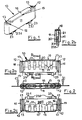
- FIG. 1 shows in the perspective view of such a recessed luminaire 10, which has an elongate housing 11, which for insertion one of the shape of the elongated hole 26 (FIG. Fig.9, 10th ) of a wall 27 is formed accordingly.
- the width of the housing 11 corresponds to the width of the elongated hole 26, while its length is greater than the length of the elongated hole 26.
- This shape allows the recessed luminaire 10 can be inserted through the opening of the elongated hole 26.
- the notches provided on both sides engage behind the positioning of the recessed luminaire 10 used as its flange 12, the wall 27 of the tube 25 and thus allow their definition.
- the flange 12 are provided for receiving fasteners with bushings 13 and can thus be formed with these, for example as screws 17.1 and passed through holes 28 in the wall of the tube 25, are attached directly to this.
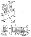
- the recessed light 10 is - as from the Figures 2 to recognize - from the housing 11, in the cavity of an LED board 20 is used with a number of LEDs 21.
- board holders 14 are provided in the two ends of the cavity.
- the LED board 20 inserted into the cavity of the housing 11 is cast with resin in order to achieve watertightness required for outdoor use.
- the end faces 22 of the LED's 21 of the board 20 through which the light exits, are directed to the inside of the light exit 15 of the housing 11.
- the LEDs 21 are connected to each other, as well as with the two, making the electrical connections to the outside enabling connector 23 with tabs 23.1 on the end faces 22 of the LED's 21 opposite side the LED board 20 are provided.
- the tabs 23.1 allow the connection of the supply line with appropriate (known from the automotive electrical system) connectors. It appears, of course, instead of the connectors also provide lead-out terminals, which then in a conventional manner to the power supply, for. be connected with plugs.
- the recessed luminaire 10 can be advantageously created with a housing formed further, which - as in FIG. 8 shown as a housing 11 '- also molded or molded.
- the arranged on the LED board 20 LEDs 21 are in molded receiving pockets 11.1. whose end faces 22 are directed towards the inside of the light exit 15.
- the LED board 20 is sealed waterproof with resin 14.1.
- This recessed luminaire is also suitable for outdoor use as well as for underwater use.
- the light emission is influenced by the type of potting. If the LEDs are completely encapsulated, resin is located between the end faces 22 of the LEDs and the inside of the light exit 15. The emerging light is widened to a nearly flat light distribution. Form the sockets of the LED's and / or their sides in cooperation with the receiving pockets 11.1 due to their fit of the insert base or surface seals, the end faces of the LED's are free of resin. If the end faces 22 of the LED's and the inner side of the light exit 15 are spaced apart, the original light exit angle of the LEDs - about 15 ° - is maintained, which causes a light distribution with highlighted light maxima of the individual LEDs.
- threaded pins 17.2 may be provided in addition to the directly acting screws arranged through the both sides of the elongated hole 26 holes 28 of the pipe wall and the passages 13 of the housing 11 against the the provided with the slot 26 wall of the tube 25 opposite Screwed pipe wall, abut against this and the recessed light 10 to the wall 27 with slot 26 so press that the flange 12 of the housing 11 engage behind this tube wall 27 and the light exit 15 in the slot 26 is such that the light exit surface 16 flush in the outside this pipe wall 27 is located. It is understood, of course, provide instead of the connectors also led out terminal ends, which are then connected in the usual way to the power supply lines.
- a spring attachment is provided.
- compression springs 18 are inserted into the passages 13 of the housing 11 with their ends formed as plug ends 18.1. After positioning the recessed luminaire 10, the other free ends are in contact with the wall 29 opposite the wall 27 of the tube 25 provided with the oblong hole 26, and hold the recessed luminaire 10 in its installed position.
- a bow spring 19 is provided, the ends of which are inserted as plug ends 19.1 inserted into the bushings 13, after positioning the recessed light 10 at the provided with the slot 26 wall 27 opposite wall 29 of the tube 25 with elastic voltage fitting, the recessed light 10 holds in its installed position.
Landscapes
- Engineering & Computer Science (AREA)
- Architecture (AREA)
- Civil Engineering (AREA)
- Structural Engineering (AREA)
- General Engineering & Computer Science (AREA)
- Non-Portable Lighting Devices Or Systems Thereof (AREA)
- Arrangement Of Elements, Cooling, Sealing, Or The Like Of Lighting Devices (AREA)
- Fastening Of Light Sources Or Lamp Holders (AREA)
- Illuminated Signs And Luminous Advertising (AREA)
- Laminated Bodies (AREA)
- Circuit Arrangement For Electric Light Sources In General (AREA)
Description
- Die Erfindung betrifft eine Einbauleuchte als Außen - und Innenleuchte mit einer in einem Gehäuse angeordneten LED-Platine, die in einen langlochähnlich geformten Ausschnitt einer Wandung insbesondere eines Rohres einsetzbar ist. [0002] Mittels lichtemittierender Dioden (LED) lässt sich elektrische Energie mit gegenüber Glühlampen erheblich verbessertem Wirkungsgrad in Licht umsetzen. Diese Art der Lichterzeugung ist nicht nur wegen des Wirkungsgrades von Vorteil, sondern auch wegen des geringen Wartungsbedarfs, haben doch LED's eine gegenüber Glühlampen erheblich vergrößerte Lebensdauer. Da sich neben LED's, die weißes Licht abstrahlen, auch LED's herstellen lassen, die farbiges Licht emittieren, lassen sich auch Beleuchtungseffekte erzielen, etwa Gefahrenwarnung durch rotes Licht oder das Erregen von Aufmerksamkeit durch blinkendes Licht und vieles mehr. So können LED's als Mittel zur energiesparenden Beleuchtung vielfach eingesetzt werden. Dabei bedingen viele LED's in Parallelschaltung eine (relativ) hohe Stromaufnahme, so dass zum Herabsetzen der Anschlussspannung vorteilhaft mehrere LED's in Reihe geschaltet werden, die Stromaufnahme jedoch auf dem Niveau einer LED gehalten wird.
- Um längliche Beleuchtungen zu erreichen, werden solche LED-Platinen auch als LED-Streifenmodule benutzt, insbesondere für Treppen und Übergänge: hier ergibt sich das Problem, dass eine ausreichende Beleuchtung besonders im Stufenbereich oder im Außenbereich nicht vorhanden ist, und somit das Unfallrisiko sehr groß ist. Die Einbauleuchte nach
EP 1 498 656 . insbesondere für Tunnel, weist eine Anzahl von modular verbundenen mit LED's bestückten Leiterplatinen auf und ist in ein rohrförmiges Schutzgehäuse so eingesetzt, dass dessen Wandung in Einschnürungen die Leiterplatine diese haltend eingreift. Die Einbauleuchte nachUS 6 145 996 für Gänge. Fluren oder Stufen in Theater ist in ähnlicher Weise in der Aufnahme gehalten, wobei sich ihre Lichtaustrittsfläche über die Oberfläche der Wandung der Aufnahme erhebt. Die in Rohre einsetzbare Einbauleuchte nachJP 070 305 474 DE 10 2005 041 333 ist in eine Öffnung oder eine Ausnehmung eines rohrförmigen Körpers eingesetzt und mit diesem so verbunden, dass ein Entnehmen zumindest erschwert ist, wobei die Lichtaustrittsfläche bündig in der Außenwandung des rohrförmigen Körpers liegt. Die Art des Einsetzens beschränkt den Einsatz dieser Einbauleuchte bei dünnwandigen Rohren und erlaubt keine wirtschaftliche Montage: weiter bedarf es bei dieser Art des Einbringens besonderer Mittel zum Halten der Einbauleuchte, die eine Auswechselbarkeit in Frage stellen. - Daraus ergibt sich die dieser Erfindung zugrunde liegende Aufgabenstellung, eine Einbauleuchte als Innen- und Außenleuchte mit einer LED-Platine in einem Gehäuse anzugeben, die auch in dünnwandige Rohre mit bündig in der Außenseite liegender Lichtaustrittsfläche auswechselbar einbaubar ist, so dass insbesondere Stufenbereiche an Treppen und Übergängen besser ausgeleuchtet werden können.
- Die Aufgabenlösung nach dieser Erfindung wird durch die im Kennzeichen des Hauptanspruchs enthaltenen Merkmale definiert: vorteilhafte Weiterbildungen und bevorzugte Ausführungsformen beschreiben die Unteransprüche.
- Nach der Erfindung besteht die Einbauleuchte im Wesentlichen aus einer länglich ausgeführten LED-Platine, die für das Lichterzeugen zuständig ist, aus einem länglichen Gehäuse in welches die LED-Platine eingesetzt ist sowie aus Mitteln zum Anschließen der LED-Platine an eine elektrische Versorgung. Dabei kann die Anzahl der LED's flexibel ausgelegt werden: auch kann die Platine mit LED's, ausgelegt in verschiedenen Farben, bestückt werden. Vorteilhaft wird die Einbauleuchte in Rohre eingesetzt. Dabei liegt deren Lichtaustrittsseite flächenbündig mit der Oberfläche des Rohrs. Dabei spielt es keine Rolle, ob das Rohr rund, rechteckig oder quadratisch ist.
- Bildet das Rohr beispielsweise einen Handlauf, ist die längliche Leuchte im Bereich des Handlaufs angeordnet. Vorteilhaft schließt dabei die Lichtaustrittsfläche bündig mit dem Handlauf ab. Ein Vorteil ist, dass der Handlauf, trotz der Baueinheit voll angefasst werden kann. Die Hand muss somit nicht den Handlauf loslassen, um an der eingesetzten Einbauleuchte vorbeizukommen. Die Leuchte wird eins mit dem Handlauf, ohne überzustehen oder den Handlauf zu stören. Die LED's des Beleuchtungsmittels (in der Einbauleuchte) leuchten durch den transparenten Ausschnitt des Gehäuses hindurch den Stufenbereich direkt aus. Dadurch wird erreicht, dass insbesondere das Licht des Leuchtmittels zum Stufenbereich hinstrahlt, so dass ein sicheres Auf- und Abgehen im Dunkeln ermöglicht wird.
- Die LED-Platine wird in ein Gehäuse eingesetzt, dessen Breite der Breite des Langlochs entspricht und dessen Länge größer ist, als die Länge des Langloches. Dadurch kann die Einbauleuchte durch das Langloch eingesetzt werden. Das Gehäuse weist einen Lichtaustritt auf, an die sich beidseits zurückspringende Flanschenden anschließen, die sich beim Einsetzen zunächst unter das eine Ende des Langloches schieben. Nach dem Einführen wird dann das Gehäuse in Position gebracht, so dass beide Flanschenden beidseits des Ausschnittes hinter der Wandung liegen.
- In vorteilhafter Weise ist das Gehäuse aus Kunststoff hergestellt, es weist einen Hohlraum für die LED-Platine auf. In einer Ausführungsform ist das Gehäuse einstückig gespritzt. Alternativ wird das Gehäuse aus einem die Platine umschließenden Harzabguss hergestellt. Dabei wird zumindest die Lichtaustrittsfläche, vorteilhaft jedoch das gesamte Gehäuse aus einem klaren Kunststoff gebildet. Die LED-Platine wird mit einer Vergussmasse, vorteilhaft einem transparenten Harz vergossen, so dass die LED-Platine wasserdicht und korrosionsgesichert im Gehäuse festgelegt ist. An dem Gehäuse sind Halterungen ausgebildet, die verschiedene Arten der Befestigungen ermöglichen, und mit denen die eingebaute Einbauleuchte in dem Rohr gehalten ist. In beiden Ausführungsformen können eingeformte Aufnahmetaschen für die LED's vorgesehen werden.
- Bei einer ersten Ausführungsform sind die Flanschenden mit Durchführungen versehen, so dass das eingesetzte Gehäuse mit Schrauben. Nieten o. dgl. direkt befestigt werden kann. Ist eine der Wandung mit Langloch gegenüberliegende Wandung vorhanden, können durch die Durchführungen auch lange Schrauben gesetzt werden, die gegen die Innenseite der gegenüberliegenden Wandung geschraubt, die Flanschenden des Gehäuses der in das Langloch eingesetzten Einbauleuchte so gegen die Innenseite der mit dem Langloch versehenen Wandung anpressen.
- Bei einer zweiten Ausführungsform, insbesondere zum Einsatz in Rohren, ist die Rückseite des Gehäuses zur Aufnahme von Federn ausgebildet, durch die sich auf der Innenseite der der Langloch-Wandung gegenüberliegenden Wandung elastisch gespannt abstützend, die Flanschenden gegen die Innenseiten der Langloch-Wandung andrücken. Als Federn können hierbei zwei in die Durchführungen der Flanschenden eingesetzte Druckfedern dienen: alternativ kann auf der Rückseite der LED-Platine eine bogenförmig ausgebildete Andrückfeder vorgesehen sein.
- Die LED-Platinen als Leuchtmittel können von Baueinheit zu Baueinheit gesteckt und so miteinander verbunden werden, so dass es keine Rolle spielt ob eine oder mehrere Einheiten angeschlossen sind. Dabei können auch LED's unterschiedlicher Farbe zum Einsatz kommen. Das Leuchtmittel selbst kann mit Bewegungsmeldern, Schaltern, Digital-Steuerungen, Zeitschaltuhr u. v. m. geschaltet werden.
- Die LED'S sind auf Platinen gesetzt, die mit die LED's verbindende Leiterbahnen aufweisen. Dabei ist das Leiterbahnenbild derart ausgebildet, dass die LED's gruppenweise so zusammengefasst sind, dass die Anschlussspannung der Versorgungsspannung der Gruppen entspricht. Hierbei können auch unterschiedliche LED-Kombinationen - etwa mit unterschiedlichen Farben abstrahlende LED's - auf einer Platine vorgesehen sein, die unterschiedliche Schaltungen zulässt. Um die LED-Platinen elektrisch anschließen zu können, sind die Anschlüsse frei herausgeführt. Alternativ sind direkte Steckanschlüsse.- etwa wie aus der KFZ-Elektrik bekannt - vorgesehen, die mit Steckanschlüssen der Versorgungsleitungen zusammenwirkend, das Anschließen an die Spannungsversorgung erlauben.
- Eine solche Leuchte als Außen- oder Innenleuchte ist für viele Einsatzmöglichkeiten geeignet. Beispiele dafür sind für den Innenbereich: Möbel, Gardaroben. Kleiderschränke (Leuchteinheit im Tragrohr für die Kleiderbügel). Beleuchtung in Wohnbereichen, Beleuchtung in Reha-Bereichen, Schreibtischbeleuchtung, Thekenbeleuchtung. Esstischbeleuchtung, Bildbeleuchtung, Arbeitsplattenbeleuchtung (Küche), u. v. m. sowie für den Außenbereich: Carportbeleuchtung: Briefkastenbeleuchtung. Beleuchtung in Eingangsbereichen. Türen- u. Türgriffe. Vordächer, PKW (Tuning und Zubehör). Caravan. Bootsbau, Brüstungsgeländer. Fahrradständer, Fahrradbügel. Stahlbau. Maschinenbau u. v. m. Dabei sind Bauart und Befestigungsart dieser in den unterschiedlichen verschiedenen Situationen genutzten Leuchten die Gleichen.
- Das Wesen der Erfindung wird an Hand der in den
Figuren 1 bis 10 dargestellten Ausführungsbeispielen näher erläutert; dabei zeigen: - Fig. 1:
- Einbauleuchte (Ansicht - Isometrie-Darstellung):
- Fig. 2:
- Einbauleuchte nach
Fig. 1 (Draufsicht). - Fig. 2a:
- Einbauleuchte (Seitenansicht).
- Fig. 2b:
- Einbauleuchte (Stirnseitenansicht - Schnitt B-B,
Fig. 2a ); - Fig. 2c:
- Einbauleuchte (Seitenansicht-Schnitt C-C.
Fig. 2 ); - Fig. 3:
- Einbauleuchte, eingebaut (Queransicht geschnitten):
- Fig. 3a:
- Stirnseitenansicht:
- Fig. 4:
- LED-Platine (Ansicht - Isometrie-Darstellung):
- Fig. 5:
- LED-Platine nach
Fig. 4 (Seitenansicht). - Fig. 5a:
- LED-Platine (Stirnseitenansicht)
- Fig. 5b:
- LED-Platine (Draufsicht);
- Fig. 6:
- Gehäuse (Ansicht - Seitenansicht),
- Fig. 6a:
- Gehäuse (Draufsicht).
- Fig. 6b:
- Gehäuse (Seitenansicht, Schnitt B-B),
- Fig. 6c:
- Gehäuse (Stirnseitenansicht, Schnitt C-C):
- Fig. 7:
- Gehäuse und LED-Platine zum Zusammenfügen:
- Fig. 8:
- Formgespritztes Gehäuse mit eingesetzter LED-Platine (Seitenansicht).
- Fig. 8a:
- Formgespritztes Gehäuse (Stirnseitenansicht, Schnitt B-B
Fig. 6a ): - Fig. 9:
- Einbauleuchte am Rohr mit Schrauben befestigt,
- Fig. 9a:
- Einbauleuchte mit Klemmstift befestigt:
- Fig. 10:
- Einbauleuchte am Rohr mit Druckfeder befestigt.
- Fig. 10a:
- Einbauleuchte mit Bügelfeder befestigt.
- Die
Figur 1 zeigt in der perspektivischen Darstellung eine solche Einbauleuchte 10, die ein längliches Gehäuse 11 aufweist, das zum Einsetzen eine der Form des Langloches 26 (Fig.9, 10 ) einer Wandung 27 entsprechend ausgebildet ist. Dabei entspricht die Breite des Gehäuses 11 der Weite des Langloches 26, während seine Länge größer ist als die Länge des Langloches 26. Dabei ermöglicht diese Form, dass die Einbauleuchte 10 durch die Öffnung des Langloches 26 eingeführt werden kann. Die beidseitig vorgesehenen Ausklinkungen hintergreifen nach Positionierung der eingesetzten Einbauleuchte 10 als deren Flanschenden 12 die Wandung 27 des Rohres 25 und erlauben so deren Festlegung. Dazu sind die Flanschenden 12 zur Aufnahme von Befestigungsmitteln mit Durchführungen 13 versehen und können so mit diesen, beispielsweise als Schrauben 17.1 ausgebildet und durch Bohrungen 28 in der Wandung des Rohres 25 geführt, direkt an dieser befestigt werden. Nach Einbau und Positionieren der Einbauleuchte 10 mit ihrem Lichtaustritt 15 in der Langlochöffnung 26 liegt der Lichtaustritt 15 in der Wandung des Rohres 25, wobei dessen Lichtaustrittsfläche 16 mit dessen Außenseite bündig ist. - Die Einbauleuchte 10 besteht - wie aus den
Figuren 2 zu erkennen - aus dem Gehäuse 11, in dessen Hohlraum eine LED-Platine 20 mit einer Anzahl von LED's 21 eingesetzt ist. Dazu sind in den beiden Enden des Hohlraumes Platinenhalter 14 vorgesehen. Um Wasserdichtheit zu erreichen und auch die Anschlussmittel vor Korrosion zu schützen, ist die in den Hohlraum des Gehäuses 11 eingesetzte LED-Platine 20 zum Erreichen einer für den Außeneinsatz notwendigen Wasserdichtheit mit Harz vergossen. Die Stirnflächen 22 der LED's 21 der Platine 20, durch die das Licht austritt, sind auf die Innenseite des Lichtaustritts 15 des Gehäuses 11 gerichtet. - Über auf der Platine vorgesehene Leiterbahnen (nicht näher dargestellt) sind die LED'S 21 sowohl untereinander, wie auch mit den beiden, das Herstellen der elektrischen Anschlüsse nach außen ermöglichenden Anschlusssteckern 23 mit Steckzungen 23.1 verbunden, die auf der den Stirnflächen 22 der LED's 21 abgewandten Seite der LED-Platine 20 vorgesehen sind. Die Steckzungen 23.1 ermöglichen das Anschließen der Versorgungsleitung mit entsprechenden (aus der KFZ-Elektrik bekannten) Steckverbindern. Dabei erscheint selbstverständlich, anstelle der Steckverbindungen auch herausgeführte Anschlüsse vorzusehen, die dann in üblicher Weise an die Stromzuführungen z.B. mit Steckern angeschlossen werden.
- Die Einbauleuchte 10 kann vorteilhaft auch mit einem weiter gebildeten Gehäuse erstellt werden, das - wie in
Figur 8 als Gehäuse 11' dargestellt - auch formgespritzt oder formgegossen ist. Dabei liegen die auf der LED-Platine 20 angeordneten LED's 21 in eingeformten Aufnahmetaschen 11.1. deren Stirnflächen 22 auf die Innenseite des Lichtaustritts 15 gerichtet sind. Die LED-Platine 20 ist mit Harz 14.1 wasserdicht vergossen. Diese Einbauleuchte ist so auch für Außeneinsatz wie auch für Einsatz unter Wasser geeignet. - Der Lichtaustritt wird dabei durch die Art des Vergießens beeinflusst. Sind die LED's völlig eingegossen, liegt Harz zwischen den Stirnflächen 22 der LED's und der Innenseite des Lichtaustritts 15. Das austretende Licht wird zu einer nahezu flächigen Lichtverteilung aufgeweitet. Bilden die Sockel der LED's und/oder deren Seiten im Zusammenwirken mit dem Aufnahmetaschen 11.1 aufgrund ihrer Passung des Einsatzes Sockel- bzw. Flächendichtungen, sind die Stirnseiten der LED's frei von Harz. Sind die Stirnflächen 22 der LED's und Innenseite des Lichtaustritts 15 beabstandet, bleibt der Original-Lichtaustrittswinkel der LED's - etwa 15 ° - erhalten, was eine Lichtverteilung mit herausgehobenen Lichtmaxima der einzelnen LED's bedingt.
- Als Befestigungsmittel für die mit einem Langloch 26 versehene Wandung 27 eines Rohres 25 eingesetzte Einbauleuchte 10 können neben direkt wirkenden Schrauben 17.1 auch Gewindestifte 17.2 vorgesehen sein, die durch die beidseits des Langloches 26 angeordneten Bohrungen 28 der Rohrwandung und die Durchführungen 13 des Gehäuses 11 gegen die der mit dem Langloch 26 versehenen Wandung des Rohres 25 gegenüberliegende Rohrwandung geschraubt, an dieser anliegen und die Einbauleuchte 10 an die Wandung 27 mit Langloch 26 so andrücken, dass die Flanschenden 12 des Gehäuses 11 diese Rohrwandung 27 hintergreifen und der Lichtaustritt 15 in dem Langloch 26 so liegt, dass die Lichtaustrittsfläche 16 bündig in der Außenseite dieser Rohrwandung 27 liegt. Dabei ist es selbstverständlich, anstelle der Steckverbindungen auch herausgeführte Anschlussenden vorzusehen, die dann in üblicher Weise an die Stromzuführungen angeschlossen werden.
- Alternativ zur Schraub-Befestigung ist eine Feder-Befestigung vorgesehen. Dazu sind bei einer Ausführungsform Druckfedern 18 mit ihren als Steckenden 18.1 ausgebildeten Enden in die Durchführungen 13 des Gehäuses 11 eingesetzt. Die anderen freien Enden liegen nach Positionierung der Einbauleuchte 10 an der der mit dem Langloch 26 versehenen Wandung 27 des Rohres 25 gegenüberliegenden Wandung 29 mit Spannung an, und halten die Einbauleuchte 10 in ihrer Einbau-Position. Bei einer zweiten Ausführungsform ist eine Bügelfeder 19 vorgesehen, deren Enden als Steckenden 19.1 ausgebildet in die Durchführungen 13 eingesetzt, nach Positionierung der Einbauleuchte 10 an der der mit dem Langloch 26 versehenen Wandung 27 gegenüberliegenden Wandung 29 des Rohres 25 mit elastischer Spannung anliegend, die Einbauleuchte 10 in ihrer Einbau-Position hält.
-
- 10
- Einbauleuchte
- 11
- Gehäuse
- 11'
- Gehäuse formgegossen oder formgespritzt
- 11.1
- Eingeformte Aufnahmetasche
- 12
- Flanschende
- 13
- Durchführung
- 14
- Platinenhalter
- 15
- Lichtaustritt
- 16
- Lichtaustrittsfläche
- 17.1
- Schraube
- 17.2
- Gewindestift
- 18
- Druckfeder
- 18.1
- Steckende
- 19:
- Bügelfeder
- 19.1
- Steckende
- 20
- LED-Platine
- 21
- LED
- 22
- (LED-)Stirnfläche
- 23
- Anschlussstecker
- 23.1
- Steckzunge
- 24
- 25
- Rohr
- 26
- Langloch
- 27
- Wandung mit Langloch
- 28
- Bohrung
- 29
- Wandung (gegenüber der Wandung 27)
Claims (8)
- Einbauleuchte als Außen - und Innenleuchte mit einer in einem Gehäuse (11) angeordneten LED-Platine (20), die in ein Langloch (26) einer Wandung (27) mit einer zusätzlichen gegenüberliegenden Wandung (29) eines Rohres einsetzbar ist, wobei das Gehäuse (11) korrespondierend zur Form des Langloches (26) eine Breite entsprechend dessen Breite und eine Länger größer als dessen Länge aufweist und wobei zwischen beiden mit Ausklinkungen versehen Flanschenden (12) des Gehäuses (11) ein Vorsprung mit Lichtaustritt (15) und Lichtaustrittsfläche (16) ausgebildet ist, dessen Höhe der Dicke der Wandung (27) entspricht, so dass die Einbauleuchte mit bündig in der Außenseite der Wandung (27) liegender Lichtaustrittsfläche (16) einbaubar ist, wobei das Gehäuse (11) einen Hohlraum aufweist, in den die mit Mitteln zum Anschließen an eine elektrische Spannungsversorgung versehene LED-Platine (20) eingesetzt ist, und wobei das Gehäuse (11) Mittel zum Festlegen der Einbauleuchte (10) an der Wandung (27) aufweist, dadurch gekennzeichnet, dass in den Flanschenden (12) als Mittel zum Festlegen der Leuchte (10) in dem Rohr (10) Gewindestifte (17.2) vorgesehen sind, die in Durchführungen (13) eingeschraubt und nach Positionierung der Leuchte (10) zu deren Festlegung bis zum abstützenden Anliegen an der der mit dem Langloch (26) versehenen Wandung (27) gegenüberliegenden Wandung (29) durchschraubbar sind.
- Einbauleuchte als Außen - und Innenleuchte mit einer in einem Gehäuse (11) angeordneten LED-Platine (20), die in ein Langloch (26) einer Wandung (27) mit einer zusätzlichen gegenüberliegenden Wandung (29) insbesondere eines Rohres einsetzbar ist, wobei das Gehäuse (11) korrespondierend zur Form des Langloches (26) eine Breite entsprechend dessen Breite und eine Länge, größer als dessen Länge, aufweist und wobei zwischen beiden mit Ausklinkungen versehen Flanschenden (12) des Gehäuses (11) ein Vorsprung mit Lichtaustritt (15) und Lichtaustrittsfläche (16) ausgebildet ist, dessen Höhe der Dicke der Wandung (27) entspricht, so dass die Einbauleuchte mit bündig in der Außenseite der Wandung (27) liegender Lichtaustrittsfläche (16) einbaubar ist, wobei das Gehäuse (11) einen Hohlraum aufweist, in den die mit Mitteln zum Anschließen an eine elektrische Spannungsversorgung versehene LED-Platine (20) eingesetzt ist, und wobei das Gehäuse (11) Mittel zum Festlegen der Einbauleuchte (10) an der Wandung (27) aufweist, dadurch gekennzeichnet, dass als Mittel zum Festlegen zumindest eine sich an der der mit dem Langloch (26) versehenen Wandung (27) gegenüberliegenden Wandung (29) abstützende Spannfeder vorgesehen ist.
- Einbauleuchte nach Anspruch 2, dadurch gekennzeichnet, dass als Spannfeder zwei paarig angeordnete Druckfedern (18) vorgesehen sind, die zum Festlegen der auf der dem Lichtaustritt (15) gegenüberliegenden Seite des Gehäuses (11) angeordnet und deren eine Enden in Durchführungen (13) in den Flanschenden (12) eingesetzt sind, und deren andere Enden nach Positionieren der Leuchte (10) an der der mit dem Langloch (26) versehenen Wandung (27) des Rohres (25) gegenüberliegenden Wandung (29) mit elastischer Spannung anliegen.
- Einbauleuchte nach Anspruch 2, dadurch gekennzeichnet, dass als als Spannfedern eine Bügelfeder (19) vorgesehen ist, die zu deren Festlegen auf der dem Lichtaustritt (15) gegenüberliegenden Seite des Gehäuses (11) angeordnet und deren Enden in die Durchführungen (13) in den Flanschenden (12) eingesetzt sind, und deren Bügel-Scheitel nach Positionieren der Leuchte (10) an der der mit dem Langloch (26) versehenen Wandung (27) gegenüberliegenden Wandung (29) mit elastischer Spannung anliegen.
- Einbauleuchte nach einem der Ansprüche 1 bis 4, dadurch gekennzeichnet, dass die LED-Platine (20) mit einer Anzahl von LED's (21) versehen ist, die in einer oder mehrere Gruppe/-en geschaltet sind, wobei jede Gruppe zumindest einen eigenen Anschluss zur Spannungsversorgung aufweist.
- Einbauleuchte nach einem der Ansprüche 1 bis 5, dadurch gekennzeichnet, dass das Gehäuse (11) als Kunststoffteil, vorzugsweise als Kunststoff-Spritzgussteil, hergestellt ist.
- Einbauleuchte nach Anspruch 5 oder 6, dadurch gekennzeichnet, dass in den Hohlraum des Gehäuses (11) Platinenhalter (14) vorgesehen sind, die die eingesetzte LED-Platine (20) aufnehmen und so halten, dass jede der LED's (21) mit ihrer Stirnfläche (22) dem Lichtaustritt (15) des Gehäuses (11) zugewandt ist, und wobei zumindest für den Lichtaustritt (15) ein klarer Kunststoff vorgesehen ist, wobei vorzugsweise der Hohlraum mit Harz ausgegossen ist.
- Einbauleuchte nach Anspruch 5 oder 6, dadurch gekennzeichnet, dass in den Hohlraum des Gehäuses (11) dem Lichtaustritt (15) zugewandt, Aufnahmetaschen (11.1) eingeformt sind, die die auf der LED-Platine (20) angeordneten LED'S (21) aufnehmen, deren Stirnfläche (22) auf die Innenseite des Lichtaustritts (15) gerichtet ist.
Applications Claiming Priority (2)
| Application Number | Priority Date | Filing Date | Title |
|---|---|---|---|
| DE202005019888U DE202005019888U1 (de) | 2005-12-21 | 2005-12-21 | Außen und Innenleuchte für die Rohrbeleuchtungseinheit |
| PCT/EP2006/070038 WO2007071746A1 (de) | 2005-12-21 | 2006-12-20 | Einbauleuchte als innen- und aussenleuchte |
Publications (2)
| Publication Number | Publication Date |
|---|---|
| EP1963734A1 EP1963734A1 (de) | 2008-09-03 |
| EP1963734B1 true EP1963734B1 (de) | 2009-05-13 |
Family
ID=36274272
Family Applications (1)
| Application Number | Title | Priority Date | Filing Date |
|---|---|---|---|
| EP06841530A Not-in-force EP1963734B1 (de) | 2005-12-21 | 2006-12-20 | Einbauleuchte als innen- und aussenleuchte |
Country Status (6)
| Country | Link |
|---|---|
| EP (1) | EP1963734B1 (de) |
| AT (1) | ATE431524T1 (de) |
| DE (2) | DE202005019888U1 (de) |
| DK (1) | DK1963734T3 (de) |
| ES (1) | ES2325224T3 (de) |
| WO (1) | WO2007071746A1 (de) |
Cited By (1)
| Publication number | Priority date | Publication date | Assignee | Title |
|---|---|---|---|---|
| CN108027120A (zh) * | 2015-06-23 | 2018-05-11 | Usm控股公司 | 用于插入家具系统的三维支撑管结构的管中的负载模块 |
Families Citing this family (4)
| Publication number | Priority date | Publication date | Assignee | Title |
|---|---|---|---|---|
| DE202006001362U1 (de) * | 2006-01-28 | 2007-06-06 | Flexo-Vertriebs-Gmbh | Einbauleuchte für einen rohrförmigen Handlauf |
| DE102006019172A1 (de) * | 2006-04-21 | 2007-10-25 | Schaefer Gmbh | Handlaufeinrichtung für Aufzugskabinen |
| DE202010000087U1 (de) | 2010-01-27 | 2011-03-17 | FILTEC GmbH Filtertechnologie für die Elektronikindustrie | Leuchteinheit insbesondere für Griffe u.dgl. |
| DE202014001288U1 (de) | 2014-02-14 | 2014-04-04 | Rene Rautenberg | Leuchtdiodenhaltevorrichtung |
Family Cites Families (4)
| Publication number | Priority date | Publication date | Assignee | Title |
|---|---|---|---|---|
| JPH07305474A (ja) * | 1994-05-12 | 1995-11-21 | Kowa Sangyo Kk | 建築物の通路の壁面に取り付ける手摺 |
| US6145996A (en) * | 1998-03-06 | 2000-11-14 | Shimada Enterprises, Inc. | Theater lighting system |
| ES2308070T3 (es) * | 2003-07-14 | 2008-12-01 | ELEKTRO PRO LIGHT KG DES BERGMEISTER MARKUS & CO. | Dispositivo de alumbrado en particular alumbrado para tuneles. |
| DE102005041333A1 (de) * | 2005-06-28 | 2007-01-25 | Michael Schillinger | Leuchtelementeinsatz für einen Beleuchtungskörper, Handlauf und Dekorelement mit einem Leuchtelementeinsatz |
-
2005
- 2005-12-21 DE DE202005019888U patent/DE202005019888U1/de not_active Expired - Lifetime
-
2006
- 2006-12-20 EP EP06841530A patent/EP1963734B1/de not_active Not-in-force
- 2006-12-20 DE DE502006003744T patent/DE502006003744D1/de active Active
- 2006-12-20 WO PCT/EP2006/070038 patent/WO2007071746A1/de not_active Ceased
- 2006-12-20 ES ES06841530T patent/ES2325224T3/es active Active
- 2006-12-20 AT AT06841530T patent/ATE431524T1/de active
- 2006-12-20 DK DK06841530T patent/DK1963734T3/da active
Cited By (2)
| Publication number | Priority date | Publication date | Assignee | Title |
|---|---|---|---|---|
| CN108027120A (zh) * | 2015-06-23 | 2018-05-11 | Usm控股公司 | 用于插入家具系统的三维支撑管结构的管中的负载模块 |
| CN108027120B (zh) * | 2015-06-23 | 2020-12-08 | 优施模优施索恩控股公司 | 用于插入家具系统的三维支撑管结构的管中的负载模块 |
Also Published As
| Publication number | Publication date |
|---|---|
| DE202005019888U1 (de) | 2006-04-13 |
| DE502006003744D1 (de) | 2009-06-25 |
| WO2007071746A1 (de) | 2007-06-28 |
| ES2325224T3 (es) | 2009-08-28 |
| EP1963734A1 (de) | 2008-09-03 |
| DK1963734T3 (da) | 2009-08-17 |
| ATE431524T1 (de) | 2009-05-15 |
Similar Documents
| Publication | Publication Date | Title |
|---|---|---|
| EP2023035B1 (de) | Leuchte | |
| DE19607208C2 (de) | Leuchtstofflampe mit auswechselbarem Leuchtteil | |
| EP0138746B1 (de) | Leuchte mit begleitender linearer Lichtquelle | |
| WO2009121559A1 (de) | Leuchte | |
| EP1963734B1 (de) | Einbauleuchte als innen- und aussenleuchte | |
| DE202011003841U1 (de) | Leuchte, insbesondere Wand- und/oder Deckenleuchte | |
| DE19801954B4 (de) | Leuchtensystem | |
| DE202011051085U1 (de) | Markisensystem und Lichtleiste hierfür | |
| DE10100877A1 (de) | LED-Leuchtmittel | |
| DE10115846B4 (de) | Modulares Lichtsystem | |
| EP0012234A1 (de) | Leuchtstofflampen-Set | |
| EP0241074B1 (de) | Anbau- bzw. Pendelleuchte für langgestreckte Entladungslampen | |
| DE202015105855U1 (de) | Längliches Lichtbandelement | |
| DE19721340A1 (de) | Leuchte | |
| DE102011016763B3 (de) | Beleuchtungseinrichtung, Leuchtkörperhalter und Leuchtkörper dafür | |
| DE20009450U1 (de) | Stromschienensystem | |
| DE202007007437U1 (de) | Leuchtkörpersystem sowie Leuchtkörper für ein Leuchtkörpersystem | |
| DE20013280U1 (de) | Hinweisleuchte | |
| DE29915823U1 (de) | Schrankrohr | |
| DE4316271A1 (de) | Beleuchtungsvorrichtung | |
| DE102005016487A1 (de) | Leuchte | |
| DE964529C (de) | Leuchte fuer roehrenfoermige Lichtquellen, insbesondere fuer Leuchtstofflampen, mit einer flachen, wahlweise unmittelbar an senkrechten oder waagerechten Flaechen befestigten Montageschiene und mit einer lichtdurchlaessigen Abdeckung | |
| DE2104420C3 (de) | Leuchte für Kraftfahrzeuge, insbesondere Schlußleuchte | |
| DE202011005398U1 (de) | Aquariumleuchte, Einsatzteil für diese und Aquariumleuchte mit Befestigungseinrichtung | |
| DE202005013529U1 (de) | Lichtring aus einer Kaltlichtkathodenröhre |
Legal Events
| Date | Code | Title | Description |
|---|---|---|---|
| PUAI | Public reference made under article 153(3) epc to a published international application that has entered the european phase |
Free format text: ORIGINAL CODE: 0009012 |
|
| 17P | Request for examination filed |
Effective date: 20080520 |
|
| AK | Designated contracting states |
Kind code of ref document: A1 Designated state(s): AT BE BG CH CY CZ DE DK EE ES FI FR GB GR HU IE IS IT LI LT LU LV MC NL PL PT RO SE SI SK TR |
|
| GRAP | Despatch of communication of intention to grant a patent |
Free format text: ORIGINAL CODE: EPIDOSNIGR1 |
|
| DAX | Request for extension of the european patent (deleted) | ||
| GRAS | Grant fee paid |
Free format text: ORIGINAL CODE: EPIDOSNIGR3 |
|
| GRAA | (expected) grant |
Free format text: ORIGINAL CODE: 0009210 |
|
| AK | Designated contracting states |
Kind code of ref document: B1 Designated state(s): AT BE BG CH CY CZ DE DK EE ES FI FR GB GR HU IE IS IT LI LT LU LV MC NL PL PT RO SE SI SK TR |
|
| REG | Reference to a national code |
Ref country code: GB Ref legal event code: FG4D Free format text: NOT ENGLISH |
|
| REG | Reference to a national code |
Ref country code: CH Ref legal event code: EP |
|
| REG | Reference to a national code |
Ref country code: IE Ref legal event code: FG4D |
|
| REF | Corresponds to: |
Ref document number: 502006003744 Country of ref document: DE Date of ref document: 20090625 Kind code of ref document: P |
|
| REG | Reference to a national code |
Ref country code: CH Ref legal event code: NV Representative=s name: BOVARD AG PATENTANWAELTE |
|
| REG | Reference to a national code |
Ref country code: DK Ref legal event code: T3 |
|
| REG | Reference to a national code |
Ref country code: ES Ref legal event code: FG2A Ref document number: 2325224 Country of ref document: ES Kind code of ref document: T3 |
|
| PG25 | Lapsed in a contracting state [announced via postgrant information from national office to epo] |
Ref country code: FI Free format text: LAPSE BECAUSE OF FAILURE TO SUBMIT A TRANSLATION OF THE DESCRIPTION OR TO PAY THE FEE WITHIN THE PRESCRIBED TIME-LIMIT Effective date: 20090513 Ref country code: LT Free format text: LAPSE BECAUSE OF FAILURE TO SUBMIT A TRANSLATION OF THE DESCRIPTION OR TO PAY THE FEE WITHIN THE PRESCRIBED TIME-LIMIT Effective date: 20090513 Ref country code: PT Free format text: LAPSE BECAUSE OF FAILURE TO SUBMIT A TRANSLATION OF THE DESCRIPTION OR TO PAY THE FEE WITHIN THE PRESCRIBED TIME-LIMIT Effective date: 20090913 |
|
| PG25 | Lapsed in a contracting state [announced via postgrant information from national office to epo] |
Ref country code: LV Free format text: LAPSE BECAUSE OF FAILURE TO SUBMIT A TRANSLATION OF THE DESCRIPTION OR TO PAY THE FEE WITHIN THE PRESCRIBED TIME-LIMIT Effective date: 20090513 Ref country code: SI Free format text: LAPSE BECAUSE OF FAILURE TO SUBMIT A TRANSLATION OF THE DESCRIPTION OR TO PAY THE FEE WITHIN THE PRESCRIBED TIME-LIMIT Effective date: 20090513 Ref country code: PL Free format text: LAPSE BECAUSE OF FAILURE TO SUBMIT A TRANSLATION OF THE DESCRIPTION OR TO PAY THE FEE WITHIN THE PRESCRIBED TIME-LIMIT Effective date: 20090513 Ref country code: SE Free format text: LAPSE BECAUSE OF FAILURE TO SUBMIT A TRANSLATION OF THE DESCRIPTION OR TO PAY THE FEE WITHIN THE PRESCRIBED TIME-LIMIT Effective date: 20090813 Ref country code: IS Free format text: LAPSE BECAUSE OF FAILURE TO SUBMIT A TRANSLATION OF THE DESCRIPTION OR TO PAY THE FEE WITHIN THE PRESCRIBED TIME-LIMIT Effective date: 20090913 |
|
| REG | Reference to a national code |
Ref country code: IE Ref legal event code: FD4D |
|
| PG25 | Lapsed in a contracting state [announced via postgrant information from national office to epo] |
Ref country code: IE Free format text: LAPSE BECAUSE OF FAILURE TO SUBMIT A TRANSLATION OF THE DESCRIPTION OR TO PAY THE FEE WITHIN THE PRESCRIBED TIME-LIMIT Effective date: 20090513 Ref country code: EE Free format text: LAPSE BECAUSE OF FAILURE TO SUBMIT A TRANSLATION OF THE DESCRIPTION OR TO PAY THE FEE WITHIN THE PRESCRIBED TIME-LIMIT Effective date: 20090513 Ref country code: CZ Free format text: LAPSE BECAUSE OF FAILURE TO SUBMIT A TRANSLATION OF THE DESCRIPTION OR TO PAY THE FEE WITHIN THE PRESCRIBED TIME-LIMIT Effective date: 20090513 |
|
| PG25 | Lapsed in a contracting state [announced via postgrant information from national office to epo] |
Ref country code: SK Free format text: LAPSE BECAUSE OF FAILURE TO SUBMIT A TRANSLATION OF THE DESCRIPTION OR TO PAY THE FEE WITHIN THE PRESCRIBED TIME-LIMIT Effective date: 20090513 |
|
| PLBE | No opposition filed within time limit |
Free format text: ORIGINAL CODE: 0009261 |
|
| STAA | Information on the status of an ep patent application or granted ep patent |
Free format text: STATUS: NO OPPOSITION FILED WITHIN TIME LIMIT |
|
| PG25 | Lapsed in a contracting state [announced via postgrant information from national office to epo] |
Ref country code: BG Free format text: LAPSE BECAUSE OF FAILURE TO SUBMIT A TRANSLATION OF THE DESCRIPTION OR TO PAY THE FEE WITHIN THE PRESCRIBED TIME-LIMIT Effective date: 20090813 |
|
| 26N | No opposition filed |
Effective date: 20100216 |
|
| PG25 | Lapsed in a contracting state [announced via postgrant information from national office to epo] |
Ref country code: MC Free format text: LAPSE BECAUSE OF NON-PAYMENT OF DUE FEES Effective date: 20100701 |
|
| PG25 | Lapsed in a contracting state [announced via postgrant information from national office to epo] |
Ref country code: GR Free format text: LAPSE BECAUSE OF FAILURE TO SUBMIT A TRANSLATION OF THE DESCRIPTION OR TO PAY THE FEE WITHIN THE PRESCRIBED TIME-LIMIT Effective date: 20090814 |
|
| PG25 | Lapsed in a contracting state [announced via postgrant information from national office to epo] |
Ref country code: RO Free format text: LAPSE BECAUSE OF FAILURE TO SUBMIT A TRANSLATION OF THE DESCRIPTION OR TO PAY THE FEE WITHIN THE PRESCRIBED TIME-LIMIT Effective date: 20090513 |
|
| REG | Reference to a national code |
Ref country code: CH Ref legal event code: PFA Owner name: DREISEWERD, ANTONIUS Free format text: DREISEWERD, ANTONIUS#IM ERLEI 2#33397 RIETBERG (DE) -TRANSFER TO- DREISEWERD, ANTONIUS#IM ERLEI 2#33397 RIETBERG (DE) |
|
| PG25 | Lapsed in a contracting state [announced via postgrant information from national office to epo] |
Ref country code: LU Free format text: LAPSE BECAUSE OF NON-PAYMENT OF DUE FEES Effective date: 20091220 |
|
| PG25 | Lapsed in a contracting state [announced via postgrant information from national office to epo] |
Ref country code: HU Free format text: LAPSE BECAUSE OF FAILURE TO SUBMIT A TRANSLATION OF THE DESCRIPTION OR TO PAY THE FEE WITHIN THE PRESCRIBED TIME-LIMIT Effective date: 20091114 |
|
| PG25 | Lapsed in a contracting state [announced via postgrant information from national office to epo] |
Ref country code: TR Free format text: LAPSE BECAUSE OF FAILURE TO SUBMIT A TRANSLATION OF THE DESCRIPTION OR TO PAY THE FEE WITHIN THE PRESCRIBED TIME-LIMIT Effective date: 20090513 |
|
| PG25 | Lapsed in a contracting state [announced via postgrant information from national office to epo] |
Ref country code: CY Free format text: LAPSE BECAUSE OF FAILURE TO SUBMIT A TRANSLATION OF THE DESCRIPTION OR TO PAY THE FEE WITHIN THE PRESCRIBED TIME-LIMIT Effective date: 20090513 |
|
| PGFP | Annual fee paid to national office [announced via postgrant information from national office to epo] |
Ref country code: DK Payment date: 20141222 Year of fee payment: 9 Ref country code: GB Payment date: 20141222 Year of fee payment: 9 Ref country code: ES Payment date: 20141125 Year of fee payment: 9 Ref country code: CH Payment date: 20141204 Year of fee payment: 9 |
|
| PGFP | Annual fee paid to national office [announced via postgrant information from national office to epo] |
Ref country code: IT Payment date: 20141126 Year of fee payment: 9 |
|
| PGFP | Annual fee paid to national office [announced via postgrant information from national office to epo] |
Ref country code: BE Payment date: 20141230 Year of fee payment: 9 |
|
| REG | Reference to a national code |
Ref country code: FR Ref legal event code: PLFP Year of fee payment: 10 |
|
| PGFP | Annual fee paid to national office [announced via postgrant information from national office to epo] |
Ref country code: AT Payment date: 20151216 Year of fee payment: 10 Ref country code: NL Payment date: 20151127 Year of fee payment: 10 |
|
| PG25 | Lapsed in a contracting state [announced via postgrant information from national office to epo] |
Ref country code: BE Free format text: LAPSE BECAUSE OF NON-PAYMENT OF DUE FEES Effective date: 20151231 |
|
| REG | Reference to a national code |
Ref country code: DK Ref legal event code: EBP Effective date: 20151231 |
|
| REG | Reference to a national code |
Ref country code: CH Ref legal event code: PL |
|
| GBPC | Gb: european patent ceased through non-payment of renewal fee |
Effective date: 20151220 |
|
| PG25 | Lapsed in a contracting state [announced via postgrant information from national office to epo] |
Ref country code: CH Free format text: LAPSE BECAUSE OF NON-PAYMENT OF DUE FEES Effective date: 20151231 Ref country code: LI Free format text: LAPSE BECAUSE OF NON-PAYMENT OF DUE FEES Effective date: 20151231 Ref country code: GB Free format text: LAPSE BECAUSE OF NON-PAYMENT OF DUE FEES Effective date: 20151220 |
|
| REG | Reference to a national code |
Ref country code: FR Ref legal event code: PLFP Year of fee payment: 11 |
|
| PG25 | Lapsed in a contracting state [announced via postgrant information from national office to epo] |
Ref country code: IT Free format text: LAPSE BECAUSE OF NON-PAYMENT OF DUE FEES Effective date: 20151220 |
|
| PG25 | Lapsed in a contracting state [announced via postgrant information from national office to epo] |
Ref country code: DK Free format text: LAPSE BECAUSE OF NON-PAYMENT OF DUE FEES Effective date: 20151231 |
|
| PG25 | Lapsed in a contracting state [announced via postgrant information from national office to epo] |
Ref country code: ES Free format text: LAPSE BECAUSE OF NON-PAYMENT OF DUE FEES Effective date: 20151221 |
|
| REG | Reference to a national code |
Ref country code: NL Ref legal event code: MM Effective date: 20170101 |
|
| REG | Reference to a national code |
Ref country code: AT Ref legal event code: MM01 Ref document number: 431524 Country of ref document: AT Kind code of ref document: T Effective date: 20161220 |
|
| PG25 | Lapsed in a contracting state [announced via postgrant information from national office to epo] |
Ref country code: NL Free format text: LAPSE BECAUSE OF NON-PAYMENT OF DUE FEES Effective date: 20170101 |
|
| PG25 | Lapsed in a contracting state [announced via postgrant information from national office to epo] |
Ref country code: AT Free format text: LAPSE BECAUSE OF NON-PAYMENT OF DUE FEES Effective date: 20161220 |
|
| REG | Reference to a national code |
Ref country code: FR Ref legal event code: PLFP Year of fee payment: 12 |
|
| REG | Reference to a national code |
Ref country code: ES Ref legal event code: FD2A Effective date: 20180704 |
|
| REG | Reference to a national code |
Ref country code: DE Ref legal event code: R082 Ref document number: 502006003744 Country of ref document: DE Representative=s name: BAUER WAGNER PELLENGAHR SROKA PATENT- & RECHTS, DE Ref country code: DE Ref legal event code: R082 Ref document number: 502006003744 Country of ref document: DE Representative=s name: BAUER WAGNER PRIESMEYER PATENT- UND RECHTSANWA, DE |
|
| PGFP | Annual fee paid to national office [announced via postgrant information from national office to epo] |
Ref country code: FR Payment date: 20191230 Year of fee payment: 14 |
|
| PG25 | Lapsed in a contracting state [announced via postgrant information from national office to epo] |
Ref country code: FR Free format text: LAPSE BECAUSE OF NON-PAYMENT OF DUE FEES Effective date: 20201231 |
|
| REG | Reference to a national code |
Ref document number: 502006003744 Country of ref document: DE Ref country code: DE Ref legal event code: R082 Representative=s name: BAUER WAGNER PELLENGAHR SROKA PATENT- & RECHTS, DE |
|
| PGFP | Annual fee paid to national office [announced via postgrant information from national office to epo] |
Ref country code: DE Payment date: 20221231 Year of fee payment: 17 |
|
| REG | Reference to a national code |
Ref country code: DE Ref legal event code: R082 Ref document number: 502006003744 Country of ref document: DE |
|
| REG | Reference to a national code |
Ref country code: DE Ref legal event code: R119 Ref document number: 502006003744 Country of ref document: DE |
|
| PG25 | Lapsed in a contracting state [announced via postgrant information from national office to epo] |
Ref country code: DE Free format text: LAPSE BECAUSE OF NON-PAYMENT OF DUE FEES Effective date: 20240702 |
|
| PG25 | Lapsed in a contracting state [announced via postgrant information from national office to epo] |
Ref country code: DE Free format text: LAPSE BECAUSE OF NON-PAYMENT OF DUE FEES Effective date: 20240702 |