EP1964537A1 - Massagevorrichtung - Google Patents
Massagevorrichtung Download PDFInfo
- Publication number
- EP1964537A1 EP1964537A1 EP07110217A EP07110217A EP1964537A1 EP 1964537 A1 EP1964537 A1 EP 1964537A1 EP 07110217 A EP07110217 A EP 07110217A EP 07110217 A EP07110217 A EP 07110217A EP 1964537 A1 EP1964537 A1 EP 1964537A1
- Authority
- EP
- European Patent Office
- Prior art keywords
- base portion
- projections
- drive means
- section
- scalp
- Prior art date
- Legal status (The legal status is an assumption and is not a legal conclusion. Google has not performed a legal analysis and makes no representation as to the accuracy of the status listed.)
- Withdrawn
Links
Images



Classifications
-
- A—HUMAN NECESSITIES
- A61—MEDICAL OR VETERINARY SCIENCE; HYGIENE
- A61H—PHYSICAL THERAPY APPARATUS, e.g. DEVICES FOR LOCATING OR STIMULATING REFLEX POINTS IN THE BODY; ARTIFICIAL RESPIRATION; MASSAGE; BATHING DEVICES FOR SPECIAL THERAPEUTIC OR HYGIENIC PURPOSES OR SPECIFIC PARTS OF THE BODY
- A61H23/00—Percussion or vibration massage, e.g. using supersonic vibration; Suction-vibration massage; Massage with moving diaphragms
- A61H23/02—Percussion or vibration massage, e.g. using supersonic vibration; Suction-vibration massage; Massage with moving diaphragms with electric or magnetic drive
-
- A—HUMAN NECESSITIES
- A61—MEDICAL OR VETERINARY SCIENCE; HYGIENE
- A61H—PHYSICAL THERAPY APPARATUS, e.g. DEVICES FOR LOCATING OR STIMULATING REFLEX POINTS IN THE BODY; ARTIFICIAL RESPIRATION; MASSAGE; BATHING DEVICES FOR SPECIAL THERAPEUTIC OR HYGIENIC PURPOSES OR SPECIFIC PARTS OF THE BODY
- A61H7/00—Devices for suction-kneading massage; Devices for massaging the skin by rubbing or brushing not otherwise provided for
- A61H7/002—Devices for suction-kneading massage; Devices for massaging the skin by rubbing or brushing not otherwise provided for by rubbing or brushing
- A61H7/004—Devices for suction-kneading massage; Devices for massaging the skin by rubbing or brushing not otherwise provided for by rubbing or brushing power-driven, e.g. electrical
- A61H7/005—Devices for suction-kneading massage; Devices for massaging the skin by rubbing or brushing not otherwise provided for by rubbing or brushing power-driven, e.g. electrical hand-held
-
- A—HUMAN NECESSITIES
- A61—MEDICAL OR VETERINARY SCIENCE; HYGIENE
- A61H—PHYSICAL THERAPY APPARATUS, e.g. DEVICES FOR LOCATING OR STIMULATING REFLEX POINTS IN THE BODY; ARTIFICIAL RESPIRATION; MASSAGE; BATHING DEVICES FOR SPECIAL THERAPEUTIC OR HYGIENIC PURPOSES OR SPECIFIC PARTS OF THE BODY
- A61H39/00—Devices for locating or stimulating specific reflex points of the body for physical therapy, e.g. acupuncture
- A61H39/04—Devices for pressing such points, e.g. Shiatsu or Acupressure
-
- A—HUMAN NECESSITIES
- A61—MEDICAL OR VETERINARY SCIENCE; HYGIENE
- A61H—PHYSICAL THERAPY APPARATUS, e.g. DEVICES FOR LOCATING OR STIMULATING REFLEX POINTS IN THE BODY; ARTIFICIAL RESPIRATION; MASSAGE; BATHING DEVICES FOR SPECIAL THERAPEUTIC OR HYGIENIC PURPOSES OR SPECIFIC PARTS OF THE BODY
- A61H2201/00—Characteristics of apparatus not provided for in the preceding codes
- A61H2201/16—Physical interface with patient
- A61H2201/1683—Surface of interface
- A61H2201/169—Physical characteristics of the surface, e.g. material, relief, texture or indicia
- A61H2201/1692—Enhanced rubbing effect
-
- A—HUMAN NECESSITIES
- A61—MEDICAL OR VETERINARY SCIENCE; HYGIENE
- A61H—PHYSICAL THERAPY APPARATUS, e.g. DEVICES FOR LOCATING OR STIMULATING REFLEX POINTS IN THE BODY; ARTIFICIAL RESPIRATION; MASSAGE; BATHING DEVICES FOR SPECIAL THERAPEUTIC OR HYGIENIC PURPOSES OR SPECIFIC PARTS OF THE BODY
- A61H2205/00—Devices for specific parts of the body
- A61H2205/02—Head
- A61H2205/021—Scalp
Definitions
- the present invention relates to a power-driven massaging device, more particularly, relates to a massaging device utilized for a massage and a wash for a scalp of a human body.
- double-purpose brushes for massaging and washing electrically are known, for example, in Japanese un-examined patent publication No. 2001-258974 .
- a vibratory head is attached via an elastic member to a casing containing a motor, and a motor shaft of the motor is protruded in the vibratory head, and an oscillator is eccentrically attached to the motor shaft.
- a brush section made of a flexible material is attached to a side surface of the vibratory head.
- the double-purpose brush comprises a brush body section serving as a base portion formed in a disk-shape and needle-like pieces serving as a number of projections protruded from a side surface of the brush body section.
- this double-purpose brush When this double-purpose brush is used, a user, first, holds the casing to place the brush section over his/her scalp and then activates a motor. As a result, vibration caused by the eccentric rotation of the oscillator built in the vibratory head, is transferred to the scalp via the vibratory head and the brush section.
- the brush section is made of such a flexible material that debris and sebum in the pores are removed without injuring the scalp while a massage is performed.
- a massaging device having a drive section and a treating section operated by the drive section, the treating section including: a base portion made of a flexible and elastic material; and a plurality of projections protruded from the base portion, wherein the base portion of the treating section is detachably attached to a frame of the drive section, and a reciprocating drive means for deflecting the base portion in a direction intersecting with a central surface of the base portion is disposed in the drive section, while a periphery of the base portion of the treating section are retained under a condition where its orientation relative to the drive section is fixed, and wherein a phantom surface connecting distal ends of a plurality of the projections under an unloaded condition is always concave regardless of any position of the reciprocating drive means, when the treating section is connected to the frame and the reciprocating drive means.
- the massaging device can deflect a central region of the base portion in a direction intersecting with the central surface of the base portion by the reciprocating drive means, keeping the periphery of the base portion of the treating section being retained in the frame.
- a plurality of the projections are repeatedly opened and closed with the complemental relation with the other and when these projections are abutted on a scalp, the scalp may be washed and massaged effectively.
- the phantom surface connecting distal ends of a plurality of the projections is always concave regardless of any position of the reciprocating drive means.
- a plurality of the distal ends of the projections can be pressed smoothly over a convex curvature such as the scalp.
- a massaging device wherein a shape of the base portion corresponding to the outermost protruded position of the reciprocating drive means is the same as its shape under a natural condition or a shape it takes when drawn relatively inwardly, when the treating section is connected to the frame and the reciprocating drive means.
- a restoring force due to the resilience of the base portion is exerted on the reciprocating drive means, and thus the reciprocating drive means is continuously pushed outwardly except when the base portion is restored into a natural condition. Accordingly, when the reciprocating drive means pushes the base portion outwardly, the base portion is restored at the same time as being pushed by the reciprocating drive means.
- the base portion can be restored substantially uniformly, without being pressed obliquely against the elastic force thereof, to provide a good performance in massaging the scalp and a treated area.
- a massaging device according to one of the foregoing aspects, wherein the base portion of the treating section is formed to be outwardly convex under a natural condition. Accordingly, when the reciprocating drive means draws the base portion, the reciprocating drive means just has to have the base portion deflected against own elasticity of the base portion. Since there is no necessity to expand the base portion in its horizontal direction, the reciprocating drive means can deflect the base portion of the treating section with a small load, thereby accomplishing a reduction of power consumption.
- a massaging device wherein a plurality of the projections are arranged to have lengths incrementally lengthening from a center toward a periphery of the base portion. Consequently, the projections in the periphery side have greater flexibility, and each of the projections arranged from a center toward a periphery of the base portion gives different stimuli onto the scalp respectively, and thus more adequate massage and wash of the scalp are attained. Furthermore, the phantom surface connecting distal ends of a plurality of the projections is always concave regardless of any position of the reciprocating drive means, when the treating section is attached to the frame. Thus, a plurality of the distal ends of the projections can be further pressed smoothly over a convex curvature such as a head.
- a massaging device according to one of the foregoing aspects, wherein, the surface of the base portion has, in a front view, a substantially circular shape, or a substantially oval shape.
- a concave curve of the phantom surface connecting distal ends of a plurality of the projections under a natural condition of the base portion has a shape corresponding to a convex curve such as a parietal region of a human body. Accordingly, a plurality of the distal ends of the projections can be further pressed smoothly over a convex curvature such as the head.
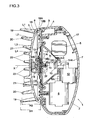
- a massaging device 1 comprises a main body 2 serving as a drive section and a treating section 3 detachably held by the main body 2.
- the main body 2 is configured to include an outer shell 4, for example made of synthetic resin, so that the outer shell can accommodate a secondary battery 5, a control circuit (not shown), an electric motor 6 actuated by the secondary battery 5 and the control circuit, and a reciprocating drive means 7 for converting the rotatory motion of a drive shaft 6A of the electric motor 6 into the reciprocatory motion.
- the extensible cover 11 is made of a flexible accordion plate to provide water-tightness for the window opening 10.
- the reciprocating drive means 7 includes a crank mechanism 13 connected to the drive shaft 6A of the electric motor 6 via a speed reduction gear mechanism 12, and a connecting rod 14, having a proximal end 14A which is rotatably coupled to an eccentric shaft 13A of the crank mechanism 13, for converting the rotary motion of the eccentric shaft 13A into the reciprocal motion.
- a thickened central region 11A of the cover 11 is sandwiched between a distal end 14B of the connecting rod 14 and a connecting member 15, which are secured by a screw N.
- a hook 16 is mounted outside of the connecting member 15. The hook 16 is constituted to reciprocate in a direction which it protrudes and recedes with respect to the main body 2 by the crank mechanism 13 in accordance with the rotation of the electric motor 6.
- the accordion extensible cover 11 is deflected keeping the water-tightness, in accordance with the reciprocal motion of the hook 16.
- the amplitude of the hook 16 is twice as the eccentric distance F from a central axis of the crank mechanism 13 to the eccentric shaft 13A (i.e. 2F).
- a switch 17 for operating the electric motor 6 is disposed in the outer shell 4.
- the treating section 3 is integrally made of soft synthetic resin or the like having flexibility and elasticity.
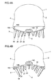
- the treating section 3 comprises a base portion 18 and four different kinds of projections 19-22 which are provided on the base portion 18.
- the base portion 18 has a substantially oval shape in front view, and is formed so that in its normal position, the center thereof has a convex curved shape smoothly raised outwardly.
- a rib 18A is integrally formed along the entire outer circumference of the base portion 18, and inside the rib 18A, an engaging portion 18B is formed so as to be engaged with and fixed on the frame 8 of the mounting plate 9 in the main body 2.
- the "fixing" includes the meaning to secure something allowing little movement.
- a hook receiving portion 18C is formed for receiving the hook 16 in the center of the base portion 18.
- a plurality of first projections 19 are arranged annularly with respect to a central axis line X of the base portion 18.
- a plurality of second projections 20 are arranged annularly with respect to the central axis line X.
- a plurality of third projections 21 are arranged symmetrically with respect to the central axis line X.
- the third projections 21 are configured so as to have an axisymmetrical placement of two sets of the projections with an arcuate arrangement.
- a plurality of fourth projections 22 are arranged annularly with respect to the central axis line X.
- the base portion 18 When the engaging portion 18B of the treating section 3 is engaged with the frame 8 and the hook receiving portion 18C is engaged with the hook 16 to connect the treating section 3 with the frame 8 and the reciprocating drive means 7, under the condition that the hook 16 is positioned at a bottom dead center, the base portion 18 is shaped same as that in its normal position. On the other hand, under the condition that the hook 16 is positioned at a top dead center, the base portion 18 has a shape with a center region more concave than a circumferential region.
- 'a bottom dead center' means a position of the hook 16 most protruding outwardly; and 'a top dead center' means to a position of the hook 16 most retracting inwardly, for convenience.
- the first projections 19 In a condition of the hook 16 positioned at the bottom dead center, i.e. when the center of the base portion 18 is most protruding outwardly, the first projections 19 have the highest heights, while the fourth projections 22 have the lowest ones. Accordingly, a phantom curved surface connecting top points of these projections 19-22 is shaped in a concave.
- the first projections 19 are disposed so as to be always greater in its heights H1 measured from the mounting plate 9 than the second projections 20 in its heights H2 despite drive conditions of the reciprocating drive means 7 (i.e. if the hook 16 is positioned at any of these: the bottom dead center; the top dead center; or a position therebetween.)
- the second projections 20 are disposed so as to be always longer in its heights H2 than the third projections 21 in its heights H3, the third projections 21 are disposed so as to be always bigger in its heights H3 than the fourth projections 22 in its heights H4 (H1>H2>H3>H4).
- FIGs. 3-5 some of the projections 19-22 are omitted to make a clear description of preferred embodiments according to the present invention since, if all actual projections 19-22 are drawn on the FIGs., many lines are crossed on the drawings, thereby some difficulties in describing may be caused.
- a user when scalp S massage is performed at hair wash, a user first holds the treating section 3, and then hooks the hook receiving portion 18C formed at center of the rear surface of the base portion 18 of the treating section 3 with the hook 16 to engage the engaging portion 18B with the frame 8. After then, the user attaches the treating section 3 to the main body 2 and holds the main body 2 of the massaging device 1, pressing each distal end of the projections 19-22 over the scalp S.
- the electric motor 6 actuated by the secondary battery 5 is activated and the drive shaft 6A of the electric motor 6 rotates.
- the crank mechanism 13 connected to the drive shaft 6A via the speed reduction gear mechanism 12 rotates and, the connecting rod 14, which is coupled to the crank mechanism 13 and the eccentric shaft 13A of the crank mechanism 13, converts the rotatory motion of the drive shaft 6A into the reciprocal motion.
- the connecting member 15 and the hook 16, both of which are connected to the connecting rod 14, are thus constituted to reciprocate in a direction which it protrudes and recedes with respect to the main body 2.
- the cover 11 is provided to keep the water-tightness for the window opening 10 of the mounting plate 9, thereby preventing water seeping into the main body 2 from the window opening 10.
- the extensible cover 11 is shaped as an accordion plate by a flexible material so as to deflect in accordance with the reciprocal motion of the connecting rod 14 and the connecting member 15, keeping the water-tightness for the window opening 10.
- the base portion 18 When the treating section 3 is connected to the frame 8 and the reciprocating drive means 7, under the condition that the hook 16 is positioned at the bottom dead center, the base portion 18 is shaped same as that in its normal position. Based on the configuration, when the reciprocating drive means 7 pushes the base portion 18, the reciprocating drive means 7 moves as if it is pulled by a restoration motion of the base portion 18. Thus, the base portion 18 can be restored uniformly, preventing the restoration from deviating from the direction, to provide a good performance in massaging the scalp S. And, when the reciprocating drive means 7 draws the base portion 18, the reciprocating drive means 7 just has to have the base portion 18 deflected against own elasticity of the base portion 18. Since there is no necessity to expand the base portion 18 in its surface direction, the reciprocating drive means 7 can deflect the base portion 18 with a small load, thereby accomplishing a reduction of power consumption.
- Each of the projections 19-22 formed integrally with the base portion 18 is moved in accordance with repeated deflections of the base portion 18 between the outwardly-protruded curved convex position and the inwardly-protruded curved concave position. Specifically, under the unloaded operation, when the hook 16 is positioned at the bottom dead center and the base portion 18 is most protruded, each distal end of the projections 19-22 is totally spaced apart from each other (in open condition). To the contrary, when the hook 16 is positioned at the top dead center and the base portion 18 is most concaved, each distal end of the projections 19-22 is totally spaced narrower to each other (in close condition). Accordingly, each of the projections 19-22 is inclined inwardly and outwardly repeatedly with respect to the central axis line X to perform a massage in a manner that the scalp S is rubbed.
- the base portion 18 is deflected repeatedly between the most outwardly-protruded curved convex position and the most inwardly-protruded curved concave position by the reciprocating drive means 7. Then, when the distal ends of the third projections 21, which are deflected relatively harder than the other projections 19, 20, 22, are pressed over the scalp S so as to constantly abut thereon, the distal ends of the third projections 21 are moved frictionally over the scalp S with slight deflection in the moving direction, so that washing and massaging on a scalp S can be performed in a manner that the scalp S is rubbed by the third projections 21.
- the distal ends of the third projections 21 have relatively sharp-pointed shapes for applying frictional or scratched stimuli onto the scalp S, thereby providing the scalp S with a good massage and wash.
- the distal ends of the first and second projections 19-20 which are longer and are deflected relatively easier than the third projections 21, are pressed over the scalp S so as to abut thereon, the distal ends of the first and second projections 19-20 are deflected widely in the moving direction in accordance with the deflection of the base portion18 repeated between the most outwardly-protruded curved convex position and the most inwardly-protruded curved concave position.
- restoring forces inhered in the deflected first and second projections provide the scalp S with stimuli in a kneading manner on massaging and washing.
- the easy deflection of the first and second projections 19-20 enables the third projections 21 to secure constant and continuous stimuli against the scalp S.
- the fourth projections 22, which are shorter than the third projections 21, abut on the scalp S in the most outwardly-protruded curved convex position of the base portion 18, but are spaced apart from the scalp S in the most inwardly-deflected curved concave position of the base portion 18.
- the treating section 3 needs to be replaced when it is tainted or broken during using repeatedly. In such situation, to detach the treating section 3 from the main body 2, the user first disengages the engaging portion 18B from the frame 8, and then removes the hook receiving portion 18C from the hook 16.
- the massaging device 1 can be used again after attaching a new or washed-up treating section 3 to the main body 2 by following the above steps reversely.
- the treating section 3 including: a base portion 18 made of a flexible and elastic material; and a plurality of projections 19-22 protruded perpendicularly from a surface of the base portion 18, is detachably retained to the drive section (e.g. the frame 8 and the reciprocating drive means 7 of the main body 2) under a condition where the orientation of the treating section 3 relative to the drive section 2 is fixed, and the base portion 18 is repeatedly deflected by the reciprocating drive means 7 in a direction orthogonal to the surface. Accordingly, the scalp S may be washed and massaged by the respective projections 19-22.
- the drive section e.g. the frame 8 and the reciprocating drive means 7 of the main body 2
- the phantom surface connecting distal ends of a plurality of the projections 19-22 under an unloaded condition is always concave regardless of any position of the reciprocating drive means 7, when the treating section 3 is attached to the main body 2.
- a plurality of the distal ends of the projections 19-22 can be pressed smoothly over a convex curvature such as the scalp S.
- a shape of the base portion 18 corresponding to the outermost protruded position of the reciprocating drive means 7 may be the same as its shape under a natural condition or a shape drawn relatively inwardly, when the treating section 3 is connected to the frame 8 and the reciprocating drive means 7.
- the connecting rod 14 of the reciprocating drive means 7 is continuously pulled outwardly except when the base portion 18 is restored into a natural condition. Accordingly, when the reciprocating drive means 7 pushes the base portion 18 outwardly, the connecting rod 14 of the reciprocating drive means 7 moves as if it is pulled by a restoration motion of the base portion 18.
- the base portion 18 can be restored uniformly, preventing the restoration from deviating from the restorative direction, to provide a good performance in massaging the scalp S.
- the massaging device 1 of the present invention may draw and deform the convex base portion 18 of the treating section 3, connected to the frame 8 and the reciprocating drive means 7, so that the base portion 18 has a shape with a center region more concave than a circumferential region, and may repeatedly deflect the base portion 18 between the curved convex position and the curved concave position. Accordingly, the projections 19-22 formed on the base portion 18 can be moved greatly to effectively perform the massage over the scalp S.
- a plurality of the projections 19-22 may be arranged to have lengths L1-L4 incrementally lengthening from a center toward a periphery of the base portion 18 (e.g. L1>L2>L3>L4). Consequently, the projections 19-22 in the periphery side have greater flexibility, and each of the projections 19-22 arranged from a center toward a periphery of the base portion 18 gives different stimuli onto the scalp S respectively, and thus more adequate massage and wash of the scalp S are attained. Furthermore, the phantom surface connecting distal ends of a plurality of the projections 19-22 is always concave regardless of any position of the reciprocating drive means 7, when the treating section 3 is attached to the frame 8. Thus, a plurality of the distal ends of the projections 19-22 can be further pressed smoothly over a convex curvature such as a head.
- the surface of the base portion 18 may have, in a front view, a substantially circular shape, or a substantially oval shape.
- a concave curve of the phantom surface connecting distal ends of a plurality of the projections 19-22 under a natural condition of the base portion 18 may be an inverted sphere or an inverted elliptical sphere corresponding to a convex curve such as a parietal region of a human body. Accordingly, a plurality of the distal ends of the projections 19-22 can be further pressed smoothly over a convex curvature such as the head.
Landscapes
- Health & Medical Sciences (AREA)
- Rehabilitation Therapy (AREA)
- Animal Behavior & Ethology (AREA)
- Pain & Pain Management (AREA)
- Physical Education & Sports Medicine (AREA)
- Life Sciences & Earth Sciences (AREA)
- Epidemiology (AREA)
- General Health & Medical Sciences (AREA)
- Public Health (AREA)
- Veterinary Medicine (AREA)
- Dermatology (AREA)
- Massaging Devices (AREA)
- Cleaning And Drying Hair (AREA)
- Brushes (AREA)
- Percussion Or Vibration Massage (AREA)
Applications Claiming Priority (1)
| Application Number | Priority Date | Filing Date | Title |
|---|---|---|---|
| JP2007048635A JP2008206902A (ja) | 2007-02-28 | 2007-02-28 | マッサージ装置 |
Publications (1)
| Publication Number | Publication Date |
|---|---|
| EP1964537A1 true EP1964537A1 (de) | 2008-09-03 |
Family
ID=39469908
Family Applications (1)
| Application Number | Title | Priority Date | Filing Date |
|---|---|---|---|
| EP07110217A Withdrawn EP1964537A1 (de) | 2007-02-28 | 2007-06-13 | Massagevorrichtung |
Country Status (5)
| Country | Link |
|---|---|
| EP (1) | EP1964537A1 (de) |
| JP (1) | JP2008206902A (de) |
| KR (1) | KR20080079970A (de) |
| CN (2) | CN101254148A (de) |
| TW (1) | TW200835472A (de) |
Cited By (11)
| Publication number | Priority date | Publication date | Assignee | Title |
|---|---|---|---|---|
| WO2012137167A2 (en) | 2011-04-08 | 2012-10-11 | L'oreal | A method of treating the scalp |
| WO2012137165A2 (en) | 2011-04-08 | 2012-10-11 | L'oreal | A hair treatment method |
| EP3025696A1 (de) | 2014-11-27 | 2016-06-01 | L'oreal | Vorrichtung zur behandlung im zusammenhang mit der talgproduktion |
| EP2443958A4 (de) * | 2009-06-16 | 2016-11-09 | Tsuin Bado Kogyo Kk | Elektrisch angetriebene bürstenvorrichtung |
| CN112568574A (zh) * | 2021-01-04 | 2021-03-30 | 哈工大机器人(中山)无人装备与人工智能研究院 | 一种按摩手和洗头机 |
| CN112568576A (zh) * | 2021-01-04 | 2021-03-30 | 哈工大机器人(中山)无人装备与人工智能研究院 | 一种后脑按摩机械臂及洗头机 |
| US20220202645A1 (en) * | 2019-09-16 | 2022-06-30 | Joseph Rogozinski | Head units for a treatment device |
| US12064387B2 (en) | 2018-12-26 | 2024-08-20 | Therabody, Inc. | Percussive therapy device with electrically connected attachment |
| US12161599B1 (en) | 2023-09-21 | 2024-12-10 | Therabody, Inc. | Systems, methods, and devices for percussive massage therapy |
| US12329711B2 (en) | 2018-12-26 | 2025-06-17 | Therabody, Inc. | Percussive therapy device with interchangeable modules |
| EP3893963B1 (de) * | 2019-05-07 | 2025-07-02 | Therabody, Inc. | Tragbares schlagmassagegerät |
Families Citing this family (11)
| Publication number | Priority date | Publication date | Assignee | Title |
|---|---|---|---|---|
| CN201286832Y (zh) * | 2008-07-25 | 2009-08-12 | 深圳市轻松科技股份有限公司 | 按摩器及其按摩手柄 |
| JP5267151B2 (ja) | 2009-01-20 | 2013-08-21 | ツインバード工業株式会社 | 電動式ブラシ装置 |
| JP2010269124A (ja) * | 2009-04-24 | 2010-12-02 | Panasonic Electric Works Co Ltd | 頭皮ケア装置 |
| JP2011044366A (ja) * | 2009-08-21 | 2011-03-03 | Twinbird Corp | 防水型電気機器 |
| JP5421211B2 (ja) * | 2010-09-16 | 2014-02-19 | パナソニック株式会社 | 頭皮ケア装置 |
| JP2012061174A (ja) * | 2010-09-16 | 2012-03-29 | Panasonic Corp | 頭皮ケア装置 |
| JP5466130B2 (ja) * | 2010-10-18 | 2014-04-09 | パナソニック株式会社 | 頭皮ケア装置 |
| JP5895206B2 (ja) * | 2011-11-10 | 2016-03-30 | パナソニックIpマネジメント株式会社 | 頭皮ケア装置 |
| JP6158719B2 (ja) * | 2014-01-24 | 2017-07-05 | ツインバード工業株式会社 | 頭皮ケア器 |
| CN105581893B (zh) * | 2016-02-29 | 2017-10-10 | 傅丹晨 | 一种头皮按摩器 |
| KR102208091B1 (ko) * | 2019-05-10 | 2021-01-26 | 김변삼 | 신체지압장치 |
Citations (3)
| Publication number | Priority date | Publication date | Assignee | Title |
|---|---|---|---|---|
| US1713756A (en) * | 1926-08-09 | 1929-05-21 | Robert H Hassler | Manually-operable head-massaging device |
| JP2006116222A (ja) * | 2004-10-25 | 2006-05-11 | Twinbird Corp | ブラシ装置 |
| JP2006141645A (ja) * | 2004-11-18 | 2006-06-08 | Twinbird Corp | ブラシ装置 |
-
2007
- 2007-02-28 JP JP2007048635A patent/JP2008206902A/ja active Pending
- 2007-03-23 TW TW096110159A patent/TW200835472A/zh unknown
- 2007-03-27 CN CNA2007100884445A patent/CN101254148A/zh active Pending
- 2007-03-28 KR KR1020070030198A patent/KR20080079970A/ko not_active Withdrawn
- 2007-06-13 EP EP07110217A patent/EP1964537A1/de not_active Withdrawn
- 2007-12-25 CN CNU2007201863117U patent/CN201127709Y/zh not_active Expired - Fee Related
Patent Citations (3)
| Publication number | Priority date | Publication date | Assignee | Title |
|---|---|---|---|---|
| US1713756A (en) * | 1926-08-09 | 1929-05-21 | Robert H Hassler | Manually-operable head-massaging device |
| JP2006116222A (ja) * | 2004-10-25 | 2006-05-11 | Twinbird Corp | ブラシ装置 |
| JP2006141645A (ja) * | 2004-11-18 | 2006-06-08 | Twinbird Corp | ブラシ装置 |
Cited By (16)
| Publication number | Priority date | Publication date | Assignee | Title |
|---|---|---|---|---|
| EP2443958A4 (de) * | 2009-06-16 | 2016-11-09 | Tsuin Bado Kogyo Kk | Elektrisch angetriebene bürstenvorrichtung |
| WO2012137167A2 (en) | 2011-04-08 | 2012-10-11 | L'oreal | A method of treating the scalp |
| WO2012137165A2 (en) | 2011-04-08 | 2012-10-11 | L'oreal | A hair treatment method |
| EP3025696A1 (de) | 2014-11-27 | 2016-06-01 | L'oreal | Vorrichtung zur behandlung im zusammenhang mit der talgproduktion |
| US12329711B2 (en) | 2018-12-26 | 2025-06-17 | Therabody, Inc. | Percussive therapy device with interchangeable modules |
| US12064387B2 (en) | 2018-12-26 | 2024-08-20 | Therabody, Inc. | Percussive therapy device with electrically connected attachment |
| US12396919B2 (en) | 2018-12-26 | 2025-08-26 | Therabody, Inc. | Percussive therapy device with electrically connected attachment |
| EP3893963B1 (de) * | 2019-05-07 | 2025-07-02 | Therabody, Inc. | Tragbares schlagmassagegerät |
| US20220202645A1 (en) * | 2019-09-16 | 2022-06-30 | Joseph Rogozinski | Head units for a treatment device |
| CN112568576A (zh) * | 2021-01-04 | 2021-03-30 | 哈工大机器人(中山)无人装备与人工智能研究院 | 一种后脑按摩机械臂及洗头机 |
| CN112568576B (zh) * | 2021-01-04 | 2022-10-25 | 哈工大机器人(中山)无人装备与人工智能研究院 | 一种后脑按摩机械臂及洗头机 |
| CN112568574A (zh) * | 2021-01-04 | 2021-03-30 | 哈工大机器人(中山)无人装备与人工智能研究院 | 一种按摩手和洗头机 |
| US12161599B1 (en) | 2023-09-21 | 2024-12-10 | Therabody, Inc. | Systems, methods, and devices for percussive massage therapy |
| US12285379B2 (en) | 2023-09-21 | 2025-04-29 | Therabody, Inc. | Systems, methods, and devices for percussive massage therapy |
| US12290486B2 (en) | 2023-09-21 | 2025-05-06 | Therabody, Inc. | Systems, methods, and devices for percussive massage therapy |
| US12478546B2 (en) | 2023-09-21 | 2025-11-25 | Therabody, Inc. | Systems, methods, and devices for percussive massage therapy |
Also Published As
| Publication number | Publication date |
|---|---|
| KR20080079970A (ko) | 2008-09-02 |
| CN201127709Y (zh) | 2008-10-08 |
| JP2008206902A (ja) | 2008-09-11 |
| TW200835472A (en) | 2008-09-01 |
| CN101254148A (zh) | 2008-09-03 |
Similar Documents
| Publication | Publication Date | Title |
|---|---|---|
| KR20080079970A (ko) | 맛사지 장치 | |
| EP1825842B1 (de) | Massagevorrichtung | |
| EP2080500A1 (de) | Massagevorrichtung | |
| JP5267151B2 (ja) | 電動式ブラシ装置 | |
| EP2084986A2 (de) | Einstellbarer Applikator | |
| JP3991360B2 (ja) | ブラシ装置及びマッサージ装置 | |
| EP1972317A1 (de) | Massagevorrichtung | |
| EP2443958A1 (de) | Elektrisch angetriebene bürstenvorrichtung | |
| KR20010100104A (ko) | 전동 두피 마사지기 | |
| JP4433501B2 (ja) | ブラシ装置及びマッサージ装置 | |
| JP4235164B2 (ja) | ブラシ装置 | |
| JP4697904B2 (ja) | ブラシ装置 | |
| JP4235160B2 (ja) | ブラシ装置 | |
| JP5357552B2 (ja) | 電動式ブラシ装置 | |
| US20100280528A1 (en) | Skin Treatment Device and Attachment | |
| JP2009018193A (ja) | ブラシ装置 | |
| JP2009165664A (ja) | マッサージ装置 | |
| JPH1052466A (ja) | マッサージ器具 | |
| JP3034547B2 (ja) | 美容器具 | |
| JP4138754B2 (ja) | ブラシ装置及びマッサージ装置 | |
| JPS61119266A (ja) | 頭皮マツサ−ジ機 | |
| EP0386327A2 (de) | Vorrichtung zum Enthaaren | |
| CN216021987U (zh) | 按摩器 | |
| CN221384288U (zh) | 一种伸缩摆动机构及按摩器 | |
| KR20140134054A (ko) | 핸디형 피부 마사지기 |
Legal Events
| Date | Code | Title | Description |
|---|---|---|---|
| PUAI | Public reference made under article 153(3) epc to a published international application that has entered the european phase |
Free format text: ORIGINAL CODE: 0009012 |
|
| AK | Designated contracting states |
Kind code of ref document: A1 Designated state(s): AT BE BG CH CY CZ DE DK EE ES FI FR GB GR HU IE IS IT LI LT LU LV MC MT NL PL PT RO SE SI SK TR |
|
| AX | Request for extension of the european patent |
Extension state: AL BA HR MK RS |
|
| AKX | Designation fees paid | ||
| REG | Reference to a national code |
Ref country code: DE Ref legal event code: 8566 |
|
| STAA | Information on the status of an ep patent application or granted ep patent |
Free format text: STATUS: THE APPLICATION IS DEEMED TO BE WITHDRAWN |
|
| 18D | Application deemed to be withdrawn |
Effective date: 20090304 |