EP1964677A2 - Dispositif doté de plusieurs unités de fonctionnement pouvant être actionnées de manière sélective - Google Patents
Dispositif doté de plusieurs unités de fonctionnement pouvant être actionnées de manière sélective Download PDFInfo
- Publication number
- EP1964677A2 EP1964677A2 EP08151859A EP08151859A EP1964677A2 EP 1964677 A2 EP1964677 A2 EP 1964677A2 EP 08151859 A EP08151859 A EP 08151859A EP 08151859 A EP08151859 A EP 08151859A EP 1964677 A2 EP1964677 A2 EP 1964677A2
- Authority
- EP
- European Patent Office
- Prior art keywords
- printing
- cylinder
- functional units
- valves
- register
- Prior art date
- Legal status (The legal status is an assumption and is not a legal conclusion. Google has not performed a legal analysis and makes no representation as to the accuracy of the status listed.)
- Withdrawn
Links
- 238000007639 printing Methods 0.000 claims abstract description 136
- 238000000034 method Methods 0.000 description 7
- 230000008569 process Effects 0.000 description 6
- 238000007645 offset printing Methods 0.000 description 5
- 238000005096 rolling process Methods 0.000 description 5
- 230000008859 change Effects 0.000 description 4
- 239000000758 substrate Substances 0.000 description 4
- 238000012546 transfer Methods 0.000 description 4
- 230000001276 controlling effect Effects 0.000 description 3
- 230000001939 inductive effect Effects 0.000 description 2
- 239000000976 ink Substances 0.000 description 2
- 239000007921 spray Substances 0.000 description 2
- 238000000429 assembly Methods 0.000 description 1
- 230000008878 coupling Effects 0.000 description 1
- 238000010168 coupling process Methods 0.000 description 1
- 238000005859 coupling reaction Methods 0.000 description 1
- 238000011161 development Methods 0.000 description 1
- 230000000694 effects Effects 0.000 description 1
- 238000012423 maintenance Methods 0.000 description 1
- 239000000463 material Substances 0.000 description 1
- 230000001105 regulatory effect Effects 0.000 description 1
- 230000008439 repair process Effects 0.000 description 1
- 239000012858 resilient material Substances 0.000 description 1
- 238000000926 separation method Methods 0.000 description 1
- 238000013519 translation Methods 0.000 description 1
- 230000001960 triggered effect Effects 0.000 description 1
- -1 web Substances 0.000 description 1
Images


Classifications
-
- B—PERFORMING OPERATIONS; TRANSPORTING
- B41—PRINTING; LINING MACHINES; TYPEWRITERS; STAMPS
- B41F—PRINTING MACHINES OR PRESSES
- B41F27/00—Devices for attaching printing elements or formes to supports
- B41F27/12—Devices for attaching printing elements or formes to supports for attaching flexible printing formes
- B41F27/1212—Devices for attaching printing elements or formes to supports for attaching flexible printing formes using pneumatic force
-
- B—PERFORMING OPERATIONS; TRANSPORTING
- B41—PRINTING; LINING MACHINES; TYPEWRITERS; STAMPS
- B41F—PRINTING MACHINES OR PRESSES
- B41F13/00—Common details of rotary presses or machines
-
- B—PERFORMING OPERATIONS; TRANSPORTING
- B41—PRINTING; LINING MACHINES; TYPEWRITERS; STAMPS
- B41F—PRINTING MACHINES OR PRESSES
- B41F27/00—Devices for attaching printing elements or formes to supports
- B41F27/005—Attaching and registering printing formes to supports
-
- B—PERFORMING OPERATIONS; TRANSPORTING
- B41—PRINTING; LINING MACHINES; TYPEWRITERS; STAMPS
- B41F—PRINTING MACHINES OR PRESSES
- B41F27/00—Devices for attaching printing elements or formes to supports
- B41F27/12—Devices for attaching printing elements or formes to supports for attaching flexible printing formes
- B41F27/1206—Feeding to or removing from the forme cylinder
-
- B—PERFORMING OPERATIONS; TRANSPORTING
- B41—PRINTING; LINING MACHINES; TYPEWRITERS; STAMPS
- B41P—INDEXING SCHEME RELATING TO PRINTING, LINING MACHINES, TYPEWRITERS, AND TO STAMPS
- B41P2227/00—Mounting or handling printing plates; Forming printing surfaces in situ
- B41P2227/10—Attaching several printing plates on one cylinder
- B41P2227/11—Attaching several printing plates on one cylinder in axial direction
-
- B—PERFORMING OPERATIONS; TRANSPORTING
- B41—PRINTING; LINING MACHINES; TYPEWRITERS; STAMPS
- B41P—INDEXING SCHEME RELATING TO PRINTING, LINING MACHINES, TYPEWRITERS, AND TO STAMPS
- B41P2227/00—Mounting or handling printing plates; Forming printing surfaces in situ
- B41P2227/50—Devices for storing printing plates
-
- B—PERFORMING OPERATIONS; TRANSPORTING
- B41—PRINTING; LINING MACHINES; TYPEWRITERS; STAMPS
- B41P—INDEXING SCHEME RELATING TO PRINTING, LINING MACHINES, TYPEWRITERS, AND TO STAMPS
- B41P2227/00—Mounting or handling printing plates; Forming printing surfaces in situ
- B41P2227/60—Devices for transferring printing plates
- B41P2227/62—Devices for introducing printing plates
-
- B—PERFORMING OPERATIONS; TRANSPORTING
- B41—PRINTING; LINING MACHINES; TYPEWRITERS; STAMPS
- B41P—INDEXING SCHEME RELATING TO PRINTING, LINING MACHINES, TYPEWRITERS, AND TO STAMPS
- B41P2227/00—Mounting or handling printing plates; Forming printing surfaces in situ
- B41P2227/60—Devices for transferring printing plates
- B41P2227/63—Devices for removing printing plates
Definitions
- the invention relates to a device having a plurality of selectively operable functional units according to the preamble of claim 1.
- a device is known with a plurality of selectively operable functional units, which device is arranged in or on a printing press outside a plate cylinder, wherein the functional units are each pneumatically actuated, the device having a valve control unit, the compressed air is supplied with three different pressures, the Valve control unit distributes the compressed air supplied to the device to the functional units, wherein the distribution of compressed air can be triggered by a machine control or on control switches.
- a cylinder of a printing press wherein the cylinder has at least two acted upon by a pressure medium actuating means and at least a first supply line for the supply of the pressure medium, wherein in the cylinder from the first supply line branching lines are provided for distributing the pressure medium to the actuating means and that in the lines to at least two actuating means each have a control valve is provided, wherein the control valve may be switchable with an electromagnetically designed actuating means.
- the invention has for its object to provide a device which is arranged outside of a plate cylinder in or on a printing press, with a plurality of pneumatically selectively operable functional units.
- the device is preferably arranged along a plate cylinder of the printing press.
- the solution shown is suitable for a device for automatic or semi-automatic assembly and / or disassembly of sections to be arranged on the plate cylinder pressure plates, for example in the case of the embodiment of the device as a register stop traverse and / or as a roller bar.
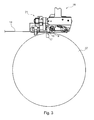
- Fig. 1 shows in highly simplified schematic form a printing machine 01, in particular a web-fed rotary printing machine 01 in the form of a printing tower 01, preferably a printing machine printing several different printing inks 01, with z. B. four in a frame 02 vertically stacked double printing units 03, wherein a substrate 05, z. B. a web of material 05, in particular a paper web 05, in the vertical direction, the double printing units 03 passes successively.
- the printing press 01 can be a printing press 01 that prints in the offset printing process, eg. B. be used in newspaper printing press 01.
- the printing machine 01 may, for. Example, use a conventional wet offset printing process, which uses a dampening solution for the printing process, or it can print in a so-called dry offset printing process in which the use of a dampening solution is not required.
- the two blanket cylinders 06 and the two plate cylinders 07 of two opposing printing units 04 of a double printing unit 03 are arranged so that their axes of rotation lie in a plane E which is inclined relative to the paper web 05 by preferably 75 ° to 88 °.
- Each printing unit 04 consisting of at least one blanket cylinder 06 and one plate cylinder 07 is assigned an inking unit 08, for example a roller inking unit 08 or a short inking unit 08. Furthermore, each printing unit 04 is assigned a dampening unit 09, for example a spray dampening unit 09. If working in a manner not shown in the "dry offset” or “waterless offset printing", no dampening solution and thus no dampening unit 09 is provided and the inking unit 08 may be formed, for example, as a pump inking unit.
- Each printing unit 04 of the printing machine 01 has at least one drive motor not shown here, which in its respective speed and preferably in an angular position of the cylinder 06 driven by it; 07 relative to at least one other cylinder 06; 07 of this printing press 01 is regulated on the basis of data provided in a data flow of an electronic machine master axis.
- the plate cylinder 07 and the blanket cylinder 06 may be drivingly connected to each other, in particular by means of gears.
- each blanket cylinder 06 and each plate cylinder 07 may be provided with its own, not shown here drive motor, in such a drive concept, a plate change on a plate cylinder 07 can be performed independently of a plate change on another plate cylinder 07th
- the printing units 04 or their plate cylinder 07 may be formed to receive a plurality of printing plates in the axial direction, in particular of 2, 3, 4, 5, 6, 7 or 8 printing plates in the axial direction, and possibly also for receiving a plurality of printing plates in the circumferential direction , in particular of two pressure plates in the circumferential direction.
- Fig. 1 are arranged on both sides of the paper web 05 in each case a double printing unit 03 arranged rubber cylinder 06 in a so-called rubber-rubber arrangement against each other, so that the mutually employed rubber cylinder 06 mutually act as a counter-pressure cylinder.
- printing units 04 can be combined to form a satellite printing unit, wherein, for example, four printing units 04 in each case are connected to one another by the remaining cylinders 06; 07 separate impression cylinder are arranged, wherein the paper web 05 is guided in each case between at least one employed on the impression cylinder transfer cylinder 06 and the impression cylinder.
- the printing tower 01 comprises two separable and mutually distance-variable frame modules 11; 12, which are displaceable along the lower and upper cross members 13, so that corresponding printing unit components are optimally accessible for setup, maintenance and possibly repair purposes.
- one of the rack modules 11; 12 stationary and the other frame module 12 or 11 be slidable.
- On each of the rack modules 11; 12 is in each case a printing unit 04 of a double printing unit 03 together with associated components such as in particular inking unit 08 and possibly dampening unit 09 are arranged.
- the printing cylinder 06; 07 i. the transfer cylinder 06 or blanket cylinder 06 and the forme cylinder 07 or plate cylinder 07, are respectively mounted in a bearing unit 10 and a linear bearing 10, wherein preferably both ends of each printing cylinder 06; 07 are mounted in a linear bearing 10.
- a linear bearing 10 supports a printing cylinder 06; 07 for rotation while allowing translation, so a linear travel of the printing cylinder 06; 07, for example, to the plate cylinder 07 from the blanket cylinder 06 z. B. to turn off for the purpose of a plate change.
- the structure of such a linear bearing 10 is known per se and essentially comprises a linearly displaceable slide or bearing block in which the radial bearing receiving the cylinder shaft is formed.
- Fig. 2 shows in connection with one of the printing units 04 of the printing press 01 or one of the forme cylinder 07, a system consisting of a forme cylinder 07 of the printing machine 01 and at least one plate changing device 20, z.
- Fig. 2 becomes clear that in the axial direction of the forme cylinder 07 more, z.
- Four Printing forms are arranged side by side can be arranged.
- the respective printing forms are each with the z.
- table-shaped feeder 20 can be fed to the forme cylinder 07, wherein each of the forme cylinder 07 to be supplied printing form placed on the feeder 20 or at least applied to this.
- the feeding device 20 may be formed in a development as a so-called disk magazine 20 in which a plurality of printing plates can be stored. In a disk magazine 20 are several printing plates z. B. stored at least in the axial direction of the forme cylinder 07 side by side.
- Fig. 2 is in each case a section A for each of the axially adjacent to each other in the axial direction of the forme cylinder 07 printing plates in association with the forme cylinder 07; B; C; D, wherein an axial extent or width of each section A; B; C; D is preferably approximately the width of that in the respective section A; B; C; D to be supplied printing form corresponds.
- the sections A; B; C; D also extend over the preferably tangentially to the lateral surface of the forme cylinder 07 employed feeder 20.
- the juxtaposed sections A; B; C; D of the forme cylinder 07 and its associated at least one feeder 20 are preferably each formed with the same width.
- the form cylinder 07 may be associated with a roller bar 18 which extends axially parallel to the forme cylinder 07 and either separately or z. B. in assembly with the feeder 20 may be formed, wherein the roller bar 18 spaced from the lateral surface of the forme cylinder 07 preferably both ends in a frame 02 (not shown here) of the printing machine 01 and the respective frame module 11; 12 is held.
- the roller bar 18 has in the axial direction of the forme cylinder 07 preferably a plurality, in each case the respective sections A; B; C; D assigned functional units, as the functional elements 19, for example, rolling elements 19, preferably rollers 19 have, for. B. three rollers 19 per section A; B; C; D, wherein the a certain section A; B; C; D assigned roles 19 z. B. regardless of the rollers 19 in another section A; B; C; D or in all other sections A; B; C; D can be employed on the lateral surface of the forme cylinder 07. It can also be provided that all juxtaposed rollers 19 of the roller bar 18 are in each case employed jointly on the lateral surface of the forme cylinder 07.
- the rollers 19 of the roller bar 18 can several, in the case of the basis of Fig. 2 to 6 explained embodiment, four not shown in detail functional units to be assigned, which are selectively pneumatically actuated by means of suitable actuators, for example, each by means of a cylinder-piston device, an elastically deformable, inflatable actuator or the like. The principle of controlling these actuators will be explained in more detail below.
- a device 21, in particular register device 21 for aligning and / or guiding an elevator 14 to be fed to the plate cylinder 07, in particular a printing plate 14 or a printing plate 14 explain. It is understood that preferably each of the plate cylinders 07 of the printing press 01 can be associated with a corresponding register device 21.
- printing forms 14 in the printing process of successive printing units 04 of a printing press 01 are arranged in register on their respective forme cylinder 07 in order to print from one another, printed by different printing units 04, but to the same print image belonging color separations of the printed product on the substrate 05 accurately print each other to print.
- a register in particular page register containing alignment and feeding of printing plates 14 to allow their respective forme cylinder 07, the participating in the printing process, z.
- printing forms 14 to be used in an offset printing method are trimmed along at least one edge, preferably along two of their edges, parallel to the two parallel lines of the type area mirror so that at least this one edge is always aligned parallel to the type area.
- the form cylinder 07 for the register setting of the printing plate 14 corresponding adjustment devices, eg. B. register pins o. ⁇ ., No longer needed.
- the means 14 laterally trimmed by means as described above is supplied with its at least one cropped edge of the forme cylinder 07 of the printing press 01, aligned during the feeding for a register-containing positioning laterally to this forme cylinder 07 and mounted there on the forme cylinder 07.
- the positionally accurate arrangement causes the lateral alignment of the printing plate 14 also that the trimmed edge of the printing plate 14 and thus the lines parallel to this edge lines of its type mirror are aligned orthogonal to the axis of the forme cylinder 07.
- the positionally accurate feeding in the axial direction of a printing forme 14 to the forme cylinder 07 takes place for. B. on a plate changing device 20 (see. Fig. 2 ) or from a plate magazine 20, preferably in such a way that a beveled end 16 of the printing plate 14 can be inserted in a longitudinal direction of the forme cylinder 07 extending below the lateral surface channel 17, wherein the channel 17 on the lateral surface of the forme cylinder 07 a z. B. slot-shaped opening, cf. Fig. 3 ,
- a holding device not shown here can be arranged in a conventional manner, the z. B. may be formed as a remotely controllable clamping device.
- FIG. 2 Another auxiliary device for mounting or removing the printing plate 14 may be associated with Fig. 2 be discussed roller bar 18, cf. also Fig. 3 ,
- the printing plate 14 with respect to the axial direction of the forme cylinder 07 in the correct position, d. H. in an orthogonal to the axial direction of the forme cylinder 07 alignment, is supplied and optionally fixed, outside of the forme cylinder 07 is a device 21 for laterally aligning and guiding the printing plate 14 produced in register, above and below also called functional unit 21, in particular register device 21, arranged.
- the register device 21 has z. B. a to the axis of the forme cylinder 07, that is, in the longitudinal direction, substantially parallel cross member 22 and a register cross member 22 and register carrier 22, the or the at least one, preferably a plurality of register stops 23; 24 carries. At least part of the functional elements 23; 24, for example register stops 23; 24 is movable on the register carrier 22 between a functional position in which it projects into the plane of the movement path of a printing form 14, and a rest position in which it does not protrude into the plane of the movement path of a printing plate 14.
- the register stops 23; 24 arranged at least substantially within the housing 22 defining a register carrier 22, while they are folded out in its operating position from the housing 22 and protrude into the plane of movement of the printing plates 14.
- Fig. 5 to 7 is in each case the functional position of the register stops 23; 24 shown.
- register stops 23; 24 these are in the case of in the Fig. 6 illustrated embodiment each held on a register carrier 22 via a respective pivot axis 25 pivotally mounted holder 26, which in turn cooperates with a disposed within the register carrier 22 cylinder piston means 27 which preferably operates pneumatically and remotely controllable, z. From the Control station of the printing press 01 can be controlled remotely.
- a carrier 30 of the housing 22 for receiving the pivot axes 25 of the holder 26 has exactly drilled pivot points and index holes.
- the position of the register stops 23; 24 are adjusted on the holder 26 in the longitudinal direction of the register carrier 22 by means of an adjusting device 28 within a defined setting range.
- register stops 23 and 24, the holder 26 together with the adjusting device 28 and the cylinder piston device 27 comprehensive device is hereinafter also functional unit 29, for example register stop means 29, called.
- the register stops 23; 24 are collapsed, for example, for an operating situation in which no printing form change should take place and pivoted when a printing plate 14 is supplied.
- one of the two register stops 23, each associated with a printing forme 14, is; 24, in the case of the embodiment of the respective register stop 24, resiliently formed. This can be done in any way, for example, either by using a resilient material for the register stop 24 or by a resilient mounting of the register stop 24.
- register stop devices 29 and functional units 29 can be composed.
- a four-page-wide register device 21 is shown, wherein in the illustration rightmost a rigid register stop 23 may be located, which can not be formed wegklappbar, and the leftmost register stop means 29 can only carry a resilient, swing-stop register stop 24 .
- By folding away certain register stop devices 29, different formats can be processed, for example, by folding away the first and third register stop devices 29, seen from the left, for printing panorama pages, printing plates 14 can be mounted in panorama format.
- the register devices 21 are a plurality of controllable valves 33; 34; 36; 37, which are preferably not permanently, but only temporarily connected via a single compressed air supply 39 or supply line 39, ie a line 39 with an external compressed air source 41, cf. Fig. 4 ,
- the valves 33; 34; 36; 37 are arranged in the form of a valve block 38 at one end of the register device 21 in the interior of the register cross 22 and the housing 22.
- the connection of the compressed air supply 39 to the register device 21 may, for. B. by means of a simply releasable coupling, z. B. a plug connection.
- valves 33; 34; 36; 37 controls 47; 48; 49; 51 is provided in the form of an actuating device 52, for example a control block 52, with which the valves 33; 34; 36; 37 selectively, ie, individually and independently of each other are preferably contactless actuated.
- the respective, in particular electrically and thus remotely triggerable controls 47; 48; 49; 51 are arranged fixed to the frame in the printing press 01, for example, but may also be arranged on or in the register crosspiece 22.
- the triggering of the respective controls 47; 48; 49; 51 can be done by a belonging to the printing machine 01 arithmetic unit.
- This arithmetic unit can z. B. be arranged in a belonging to the printing press 01 control station.
- the controls 47; 48; 49; 51 can for actuating the respective valves 33; 34; 36; 37 use a preferably magnetic or optionally inductive active principle.
- the respective valves 33; 34; 36; 37 are actuated by means of a radio signal.
- FIGS. 9 and 10 show three different embodiments of the respective pneumatic circuit of each of the valves 33; 34; 36; 37.
- the valves 33 remain; 34; 36; 37 after its operation in a self-holding, ie in a self-holding Operating condition.
- FIGS. 9 and 10 is in each case by a connected to the valve circuit working cylinder 53 from the valve 33; 34; 36 and 37 to be actuated cylinder-piston device 27 of the respective functional unit 29, z.
- the control of the rollers 19 of the roller bar 18 can take place in a manner corresponding to the preceding embodiments via a single supply line, provided on the roller bar 18 valves and corresponding possibly contactless controls, as has been described above in connection with the register device 21.
- At least one further device 21 with a plurality of pneumatically selectively operable functional units 29 may be arranged outside at least one of the plate cylinders 07 in or on the printing press 01 Function units 29 as well as the register device 21 at least one functional element 23; 24, wherein the device 21 also has a plurality of controllable valves 33; 34; 36; 37, wherein the valves 33; 34; 36; 37 are connected via a single compressed air supply 39 or line 39 with an external compressed air source 41.
- the valves 33; 34; 36; 37 are preferably in the form of a valve block 38 or a valve terminal 38 z.
- valves 33; 34; 36; 37 associated controls 47; 48; 49; 51 are provided, with which the valves 33; 34; 36; 37 selectively, ie individually and independently of each other preferably without a mechanical contact contact can be actuated.
- the controls 47; 48; 49; 51 can for actuating the respective valves 33; 34; 36; 37 use a preferably magnetic or optionally inductive active principle.
- the respective valves 33; 34; 36; 37 are actuated by means of a radio signal.
- One or more valve islands 38 may be provided in the device 21.
- the proposed devices 21 have in common that the respective device 21 is assigned only a single pneumatic supply line 39, said compressed air supply 39 is not permanently, but only as needed connected to the respective device 21, wherein the compressed air distribution to preferably substantially identical or at least similar Functional units 29 of this device 21 by means arranged in the respective device 21 valves 33; 34; 36; 37 takes place, these valves 33; 34; 36; 37 by means disposed outside the respective device 21 controls 47; 48; 49; 51 are contactlessly actuated.
- the proposed device 21 can also be a plate magazine 20, an automatic feeder for to be arranged on the forme 07 printing plates 14 or at least one printing plate 14 the forme cylinder 07 supplying feeder 20 each having a plurality of external Control unit be made of actuatable functional units 29.
- the respective functional units 29 z.
- each as a pneumatically actuated conveyor for conveying one or more printing plates 14 or as a pneumatically actuated aligning device with respect to a plate cylinder 07 entegot aligning at least one printing form 14 may be formed.
Landscapes
- Engineering & Computer Science (AREA)
- Mechanical Engineering (AREA)
- Rotary Presses (AREA)
- Supply, Installation And Extraction Of Printed Sheets Or Plates (AREA)
- Inking, Control Or Cleaning Of Printing Machines (AREA)
Applications Claiming Priority (2)
| Application Number | Priority Date | Filing Date | Title |
|---|---|---|---|
| DE102007010298 | 2007-03-02 | ||
| DE102007000639A DE102007000639B3 (de) | 2007-03-02 | 2007-11-07 | Vorrichtung mit mehreren selektiv betätigbaren Funktionseinheiten |
Publications (2)
| Publication Number | Publication Date |
|---|---|
| EP1964677A2 true EP1964677A2 (fr) | 2008-09-03 |
| EP1964677A3 EP1964677A3 (fr) | 2012-04-04 |
Family
ID=39587568
Family Applications (1)
| Application Number | Title | Priority Date | Filing Date |
|---|---|---|---|
| EP08151859A Withdrawn EP1964677A3 (fr) | 2007-03-02 | 2008-02-25 | Dispositif doté de plusieurs unités de fonctionnement pouvant être actionnées de manière sélective |
Country Status (2)
| Country | Link |
|---|---|
| EP (1) | EP1964677A3 (fr) |
| DE (1) | DE102007000639B3 (fr) |
Citations (3)
| Publication number | Priority date | Publication date | Assignee | Title |
|---|---|---|---|---|
| DE10238177B3 (de) | 2002-08-21 | 2004-02-05 | Koenig & Bauer Ag | Vorrichtung zum Andrücken eines Aufzugs an einen Zylinder einer Druckmaschine mit Hilfe von in Umfangsrichtung des Zylinders voneinander beabstandeten ersten und zweiten Wälzelementen |
| DE10244574A1 (de) | 2002-09-25 | 2004-04-15 | Koenig & Bauer Ag | Zylinder einer Druckmaschine |
| DE102005017182A1 (de) | 2005-04-13 | 2006-10-19 | Man Roland Druckmaschinen Ag | Vorrichtung und Verfahren zum Andrücken einer Bespannung an einen Druckwerkzylinder einer Rotationsdruckmaschine |
Family Cites Families (2)
| Publication number | Priority date | Publication date | Assignee | Title |
|---|---|---|---|---|
| DE102004023434A1 (de) * | 2004-05-10 | 2005-12-08 | Maschinenfabrik Wifag | Rotationsdruckmaschine mit Saugvorrichtung, Saugvorrichtung und Verfahren zum Wechseln einer Druckform |
| ATE526162T1 (de) * | 2004-05-14 | 2011-10-15 | Koenig & Bauer Ag | Verfahren zur herstellung einer druckform und zum zuführen derselben an einen formzylinder einer druckmaschine |
-
2007
- 2007-11-07 DE DE102007000639A patent/DE102007000639B3/de not_active Expired - Fee Related
-
2008
- 2008-02-25 EP EP08151859A patent/EP1964677A3/fr not_active Withdrawn
Patent Citations (3)
| Publication number | Priority date | Publication date | Assignee | Title |
|---|---|---|---|---|
| DE10238177B3 (de) | 2002-08-21 | 2004-02-05 | Koenig & Bauer Ag | Vorrichtung zum Andrücken eines Aufzugs an einen Zylinder einer Druckmaschine mit Hilfe von in Umfangsrichtung des Zylinders voneinander beabstandeten ersten und zweiten Wälzelementen |
| DE10244574A1 (de) | 2002-09-25 | 2004-04-15 | Koenig & Bauer Ag | Zylinder einer Druckmaschine |
| DE102005017182A1 (de) | 2005-04-13 | 2006-10-19 | Man Roland Druckmaschinen Ag | Vorrichtung und Verfahren zum Andrücken einer Bespannung an einen Druckwerkzylinder einer Rotationsdruckmaschine |
Also Published As
| Publication number | Publication date |
|---|---|
| EP1964677A3 (fr) | 2012-04-04 |
| DE102007000639B3 (de) | 2008-08-07 |
Similar Documents
| Publication | Publication Date | Title |
|---|---|---|
| DE102013217948B4 (de) | Druckmaschine für den Wertpapierdruck mit einem Orlof-Offsetdruckwerk | |
| EP2736723B1 (fr) | Cylindre de plaque | |
| DE19745136B4 (de) | Rotationsbogendruckmaschine | |
| DE102009002103B4 (de) | Druckmaschine und ein Verfahren zum Bedrucken eines bahnförmigen Bedruckstoffs | |
| DE19916257B4 (de) | Mehrfarben-Druckmaschine zum wahlweisen Bedrucken von einzelnen Bahnen oder von zwei Bahnen | |
| EP2197679A1 (fr) | Groupe d'impression, machine à imprimer, et procédé d'exploitation d'un groupe d'impression | |
| DE4218422A1 (de) | Bogen-Offsetrotationsdruckmaschine mit herausnehmbarem Eindruck- oder Veredelungswerk | |
| EP2029362B1 (fr) | Procede pour faire fonctionner une unité d'impression satellite a neuf cylindres | |
| EP1708887A2 (fr) | Procedes pour compenser un allongement transversal et/ou un allongement longitudinal d'une matiere d'impression et machine a imprimer comportant plusieurs groupes d'impression produisant une image imprimee sur une matiere d'impression | |
| EP0995596B1 (fr) | Dispositif et procédé pour la mise en oeuvre d'un changement de plaques en marche | |
| EP1226937B1 (fr) | Entraînement sans arbre à moteur pour une machine d'impression avec un rouleau d'encrage anilox | |
| EP1708886B2 (fr) | Machine a imprimer faisant appel a un dispositif et a un procede pour compenser un allongement longitudinal et un allongement transversal d'une bande de matiere d' impression imprimee dans differents groupes d'impression | |
| EP0924069A2 (fr) | Dispositif de guidage de feuilles dans une machine à imprimer | |
| CH685380A5 (de) | Rotationsdruckmaschine. | |
| DE10232109A1 (de) | Offsetdruckwerk und Offsetdruckverfahren | |
| DE102007000639B3 (de) | Vorrichtung mit mehreren selektiv betätigbaren Funktionseinheiten | |
| EP1927475B1 (fr) | Unité d'imprimante satéllite et tour d'impression | |
| EP1060882B1 (fr) | Système à repiquer dans une machine rotative | |
| DE102007033589B3 (de) | Vorrichtung zum seitlichen Ausrichten mindestens eines einem Zylinder einer Druckmaschine zuzuführenden Aufzugs | |
| DE10003107B4 (de) | Verfahren und Vorrichtung für einen Transport einer Bedruckstoffbahn zwischen Funktionseinheiten einer Rotationsdruckmaschine in besonderen Betriebssituationen | |
| EP3235641B1 (fr) | Machine de traitement comportant un cylindre de préparation amovible | |
| DE10232864A1 (de) | Satellitendruckmaschine zum Bedrucken von Bögen | |
| EP1927468B1 (fr) | Unités d'imprimante satellite comprenant neuf cylindres | |
| DE10338193B4 (de) | Eindruckwerksgruppe in einer Gummituch-Gummituch-Konfiguration | |
| EP1938985A2 (fr) | Plaque d'impression pour un cylindre à plaque ou plaques d'impression pour cylindres à plaques |
Legal Events
| Date | Code | Title | Description |
|---|---|---|---|
| PUAI | Public reference made under article 153(3) epc to a published international application that has entered the european phase |
Free format text: ORIGINAL CODE: 0009012 |
|
| AK | Designated contracting states |
Kind code of ref document: A2 Designated state(s): AT BE BG CH CY CZ DE DK EE ES FI FR GB GR HR HU IE IS IT LI LT LU LV MC MT NL NO PL PT RO SE SI SK TR |
|
| AX | Request for extension of the european patent |
Extension state: AL BA MK RS |
|
| PUAL | Search report despatched |
Free format text: ORIGINAL CODE: 0009013 |
|
| AK | Designated contracting states |
Kind code of ref document: A3 Designated state(s): AT BE BG CH CY CZ DE DK EE ES FI FR GB GR HR HU IE IS IT LI LT LU LV MC MT NL NO PL PT RO SE SI SK TR |
|
| AX | Request for extension of the european patent |
Extension state: AL BA MK RS |
|
| RIC1 | Information provided on ipc code assigned before grant |
Ipc: B41F 27/00 20060101ALI20120227BHEP Ipc: B41F 13/00 20060101ALI20120227BHEP Ipc: B41F 27/12 20060101AFI20120227BHEP |
|
| 17P | Request for examination filed |
Effective date: 20120312 |
|
| STAA | Information on the status of an ep patent application or granted ep patent |
Free format text: STATUS: THE APPLICATION HAS BEEN WITHDRAWN |
|
| 18W | Application withdrawn |
Effective date: 20121015 |