EP1964715A2 - Dispositif d'adaptateur pour une poignée - Google Patents
Dispositif d'adaptateur pour une poignée Download PDFInfo
- Publication number
- EP1964715A2 EP1964715A2 EP07018341A EP07018341A EP1964715A2 EP 1964715 A2 EP1964715 A2 EP 1964715A2 EP 07018341 A EP07018341 A EP 07018341A EP 07018341 A EP07018341 A EP 07018341A EP 1964715 A2 EP1964715 A2 EP 1964715A2
- Authority
- EP
- European Patent Office
- Prior art keywords
- adapter device
- handle
- deformation
- web
- deformation element
- Prior art date
- Legal status (The legal status is an assumption and is not a legal conclusion. Google has not performed a legal analysis and makes no representation as to the accuracy of the status listed.)
- Granted
Links
Images

Classifications
-
- B—PERFORMING OPERATIONS; TRANSPORTING
- B60—VEHICLES IN GENERAL
- B60R—VEHICLES, VEHICLE FITTINGS, OR VEHICLE PARTS, NOT OTHERWISE PROVIDED FOR
- B60R21/00—Arrangements or fittings on vehicles for protecting or preventing injuries to occupants or pedestrians in case of accidents or other traffic risks
- B60R21/02—Occupant safety arrangements or fittings, e.g. crash pads
- B60R21/055—Padded or energy-absorbing fittings, e.g. seat belt anchors
-
- B—PERFORMING OPERATIONS; TRANSPORTING
- B60—VEHICLES IN GENERAL
- B60N—SEATS SPECIALLY ADAPTED FOR VEHICLES; VEHICLE PASSENGER ACCOMMODATION NOT OTHERWISE PROVIDED FOR
- B60N3/00—Arrangements or adaptations of other passenger fittings, not otherwise provided for
- B60N3/02—Arrangements or adaptations of other passenger fittings, not otherwise provided for of hand grips or straps
- B60N3/026—Arrangements or adaptations of other passenger fittings, not otherwise provided for of hand grips or straps characterised by the fixing means
-
- B—PERFORMING OPERATIONS; TRANSPORTING
- B60—VEHICLES IN GENERAL
- B60R—VEHICLES, VEHICLE FITTINGS, OR VEHICLE PARTS, NOT OTHERWISE PROVIDED FOR
- B60R13/00—Elements for body-finishing, identifying, or decorating; Arrangements or adaptations for advertising purposes
- B60R13/02—Internal Trim mouldings ; Internal Ledges; Wall liners for passenger compartments; Roof liners
- B60R13/0206—Arrangements of fasteners and clips specially adapted for attaching inner vehicle liners or mouldings
-
- B—PERFORMING OPERATIONS; TRANSPORTING
- B60—VEHICLES IN GENERAL
- B60R—VEHICLES, VEHICLE FITTINGS, OR VEHICLE PARTS, NOT OTHERWISE PROVIDED FOR
- B60R13/00—Elements for body-finishing, identifying, or decorating; Arrangements or adaptations for advertising purposes
- B60R13/02—Internal Trim mouldings ; Internal Ledges; Wall liners for passenger compartments; Roof liners
- B60R13/0212—Roof or head liners
- B60R13/0225—Roof or head liners self supporting head liners
Definitions
- the invention relates to an adapter device for a handle.
- the invention also relates to a motor vehicle with at least one such adapter device.
- an adapter device which is designed as a storage unit for a arranged in the interior of a vehicle, manually detectable handle, wherein the bearing unit consists of a vehicle-fixed base part and on the other hand in a possible impact direction of a person slidably held bearing block part, wherein between the base part and the Bearing part at least one deformation element is mounted.
- the bearing unit consists of a vehicle-fixed base part and on the other hand in a possible impact direction of a person slidably held bearing block part, wherein between the base part and the Bearing part at least one deformation element is mounted.
- the DE 197 47 704 A1 is also proposed to hold a grip handle designed as a roof grab handle on two spaced bearing block parts, which are each held displaceably via a deformation element. This arrangement is relatively expensive to assemble and also involves the risk that the bearing block part jammed during the deformation process in the base part.
- the DE 101 40 338 A1 discloses an adapter device for attaching a handle to a wall, preferably in the passenger compartment of a motor vehicle, wherein the adapter device is elongated formed with an at least partially substantially inverted U-shaped cross-section, wherein the outer U-leg can be fixed to the wall and on the inner U-leg a handle is attachable, wherein the U-shaped cross section is composed of at least two longitudinally extending sub-profiles.
- An adapter device of the type mentioned should be designed as possible, that on the one hand can absorb tensile forces when a person holds on to the handle or pulls on this (case of normal use). On the other hand, should such an adapter device absorb as much energy when an occupant of a motor vehicle on the handle, eg with his head, bounces (crash case).
- Known adapter devices have in terms of their functionality in at least one of the two load cases, i. in the case of normal use or in the event of a crash, significant deficits.
- Object of the present invention is to provide an adapter device for a handle, which avoids the aforementioned disadvantages and is improved over known adapter devices in that high stability is given in the case of normal use with significantly improved deformation properties in the event of a crash ,
- an adapter device of the type mentioned at the outset has a deformation element with at least two end regions, wherein the end regions of the deformation element are connected to one another by at least one web and the end regions each have at least one fastening element for the handle, wherein the deformation element is designed such that it forms in a first load case is supported by a holding element, and that it deforms in a second load case in the region of the at least one web.
- a handle may be subject to stress in a pulling direction, i. in the case of normal use, are stored extremely stable without impairing the energy-absorbing deformation properties of the adapter device in the event of a crash.
- the end regions of the deformation element may correspond to openings of the retaining element, wherein the end regions may be formed substantially as pots and preferably have edge regions which at least partially overlap with the retaining element.
- a desired bending line can advantageously be defined in the region of the at least one web.
- a desired, predefined deformability of the deformation element can be set with advantage in that the at least one web of the deformation element has at least one edge which is notched in order to define a desired bending line.
- the bracket forming a bracket 1 may be connected to attachment points 8 with a body part 7 (see FIG. 4) of a motor vehicle.
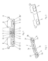
- the deformation element 2 has two end regions, each with at least one fastening element 6 for a handle 10 (see FIG. 5).
- the handle 10 may preferably be formed bow-shaped, wherein the ends of the bow-shaped Grab handles can be attached to the fasteners 6.
- the fastening elements 6 are designed, for example, as fastening openings.
- the deformation element 2 is shown in the drawings in its undeformed state.
- the deformation element 2 has two end regions.
- the at least two end regions of the deformation element 2 are preferably formed as pots 2a ', 2a "The pots 2a', 2a” are arranged in such a way that they penetrate openings 5 (see Fig. 3) of the holding element 1.
- the pots 2a ', 2a "have edge regions 2b', 2b", wherein the edge regions 2b ', 2b "overlap with the holding element 1 or rest on the holding element 1.
- an undesired deformation of the deformation element 2 in the case of the normal Use prohibited.
- the deformation element 2 has one or more, in the example shown, two webs 2c which connect the end regions of the deformation element 2 to one another.
- the at least one web 2c of the deformation element 2 can be connected to the holding element 1, e.g. in the web center, be connected for example by a spot weld 3.
- the at least one web 2c is designed such that one or more desired bending lines 4 ', 4 "are defined altered material properties and / or caused by one or more notches.
- the at least one web 2c of the deformation element 2 can have edges which are preferably angled or bent with respect to the web surface.
- the desired bending lines 4 'and 4 " are preferably assigned to the end regions of the deformation element 2, ie the pots 2a' and 2a", respectively.
- a mark on the right pot 2a " would also make a clear impact more pronounced deformation at the right-hand bend lines 4 "are made than at the left-hand bend lines 4 '.
- FIG. 2 shows the deformation element 2 with two webs 2 c, which connect the end regions of the deformation element 2.
- the end regions are formed in the example shown as pots 2a with edge regions 2b.
- the pots 2a of the deformation element 2 have fastening elements 6 for a handle 10, wherein the handle 10 can be mounted on the inside 2f of the pots 2a opposite outside 2g (see Fig. 4 and 5) of the pots 2a.
- Fig. 3 shows the bracket formed as a holding element 1 in a perspective view.
- the holding element 1 has two openings 5, which correspond to the pots 2a (see FIG. 2) of the deformation element 2.
- the openings 5 and the pots 2a are preferably adapted to each other in terms of their shape.
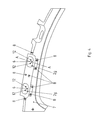
- Fig. 4 shows the adapter device attached to a body part 7 of the motor vehicle.
- the adapter device is connected to the fastening parts 8 with the body part 7.
- the connection of the holding element 1 to the body part 7 is preferably made cohesively.
- the retaining element 1 is welded to the attachment points 8 with the shell of the motor vehicle.
- the adapter device is attached to a roof frame above the door of a motor vehicle.
- the fastening elements 6 designed as fastening openings for the holding handle 10 (see FIG. 5) can be seen.
- a bracket-shaped handle 10 for example, a rotation 12 may be provided.
- Fig. 5 shows a section through the adapter device and the body part 7 along the line AA in Fig. 4.
- the handle 10 is schematically indicated in the unused position.
- the handle 10 is attached to the outside 2 g of the pot 2 a of the deformation element 2.
- the inside 2f of the pot 2a faces a body part 7 and the vehicle outside.
- the edge region 2b of the pot 2a and the webs 2c (not shown in detail in FIG. 5) (see FIGS. 1 and 2) of the deformation element 2 are arranged on the side of the holding element 1 which faces the vehicle exterior.
- the edge region 2b of the pot 2a When loaded in a pulling direction p, the edge region 2b of the pot 2a is pressed against the holding element 1.
- the holding element 1 is stably supported by its end region formed substantially in the form of a pot 2a with edge region 2b both in the pulling direction p and laterally, ie perpendicular to the pulling direction p.
- the deformation element 2 When loaded in the direction of impact i, the deformation element 2 can give way, since the pot 2a is movably mounted in the direction of impact i.
- a deformation of the deformation element 2 in particular in the region of the crease lines 4 ', 4 "(see FIG. 1) is first accelerated in the direction of impact and describes a movement path around the corresponding bending line 4 ', 4 ".
- the minimum force required in the direction of deformation of the deformation element in the direction of impact i can be achieved by a corresponding configuration of the at least one web 2c (see FIGS 2), eg by a corresponding formation of notches and / or correspondingly pronounced material properties
- the holding element 1 preferably does not deform in the event of a crash If the impact energy is correspondingly high, the deformation element 2 with the pots 2a, 2a ', 2a "in FIG Crash case moves at least almost completely on the vehicle outside facing side of the support member 1.
- the adapter device is preferably arranged such that between the adapter device and the handle 10 is a mold 11 of the passenger compartment. Between the mold head 11 and a body part 7, an air bag 9 is preferably arranged below the adapter device.
Landscapes
- Engineering & Computer Science (AREA)
- Mechanical Engineering (AREA)
- Transportation (AREA)
- Vibration Dampers (AREA)
- Lock And Its Accessories (AREA)
- Emergency Lowering Means (AREA)
- Passenger Equipment (AREA)
- Casings For Electric Apparatus (AREA)
Applications Claiming Priority (1)
| Application Number | Priority Date | Filing Date | Title |
|---|---|---|---|
| DE102006053781A DE102006053781B4 (de) | 2006-11-15 | 2006-11-15 | Adaptervorrichtung für einen Haltegriff |
Publications (3)
| Publication Number | Publication Date |
|---|---|
| EP1964715A2 true EP1964715A2 (fr) | 2008-09-03 |
| EP1964715A3 EP1964715A3 (fr) | 2009-06-17 |
| EP1964715B1 EP1964715B1 (fr) | 2011-05-18 |
Family
ID=39311149
Family Applications (1)
| Application Number | Title | Priority Date | Filing Date |
|---|---|---|---|
| EP07018341A Ceased EP1964715B1 (fr) | 2006-11-15 | 2007-09-19 | Dispositif d'adaptateur pour une poignée |
Country Status (5)
| Country | Link |
|---|---|
| US (1) | US7607708B2 (fr) |
| EP (1) | EP1964715B1 (fr) |
| JP (1) | JP5161542B2 (fr) |
| CN (1) | CN101181883B (fr) |
| DE (1) | DE102006053781B4 (fr) |
Families Citing this family (11)
| Publication number | Priority date | Publication date | Assignee | Title |
|---|---|---|---|---|
| DE102008025740A1 (de) * | 2008-05-29 | 2009-12-03 | GM Global Technology Operations, Inc., Detroit | Halteblech und Halteblechanordnung für einen Haltegriff in einem Kraftfahrzeug |
| US7896417B2 (en) * | 2009-07-31 | 2011-03-01 | Honda Motor Co., Ltd. | Grab handle bracket |
| JP5534145B2 (ja) * | 2009-08-25 | 2014-06-25 | スズキ株式会社 | アシスタントグリップの取り付け構造 |
| DE102009048338A1 (de) * | 2009-10-06 | 2011-04-21 | GM Global Technology Operations, Inc., Detroit | Befestigungseinrichtung eines Haltegriffs an einem in Fahrtrichtung verlaufenden Dachholm eines Kraftfahrzeuges |
| JP5608749B2 (ja) * | 2010-07-23 | 2014-10-15 | 本田技研工業株式会社 | 車両の内装部品の配設構造 |
| DE102011015543A1 (de) * | 2011-03-30 | 2012-10-04 | GM Global Technology Operations LLC (n. d. Gesetzen des Staates Delaware) | Haltevorrichtung |
| US9994166B2 (en) * | 2015-08-19 | 2018-06-12 | Ford Global Technologies, Llc | Dual molded grab handle spacer for a motor vehicle |
| FR3054504A1 (fr) * | 2016-07-27 | 2018-02-02 | Peugeot Citroen Automobiles Sa | Dispositif de poignee de maintien a entretoise |
| US10071665B2 (en) * | 2016-10-27 | 2018-09-11 | Honda Motor Co., Ltd. | Grab handle assembly for use in a vehicle |
| DE102018217800B4 (de) * | 2018-10-17 | 2024-12-05 | Volkswagen Aktiengesellschaft | Adapter für einen Haltegriff im Innenraum eines Kraftfahrzeugs |
| DE102021212073A1 (de) | 2021-10-26 | 2023-04-27 | Volkswagen Aktiengesellschaft | Befestigungsadapter mit begrenztem Schweißbereich und Kraftfahrzeug |
Citations (2)
| Publication number | Priority date | Publication date | Assignee | Title |
|---|---|---|---|---|
| DE19747704A1 (de) | 1997-10-29 | 1999-05-06 | Volkswagen Ag | Griffeinrichtung für den Innenraum eines Fahrzeugs |
| DE10140338A1 (de) | 2001-08-16 | 2003-02-27 | Volkswagen Ag | Adapter zur Anbringung eines Haltegriffs oder dergleichen |
Family Cites Families (12)
| Publication number | Priority date | Publication date | Assignee | Title |
|---|---|---|---|---|
| DE3222810A1 (de) * | 1982-06-18 | 1983-12-22 | Gebr. Happich Gmbh, 5600 Wuppertal | Haltegriff od. dgl. fuer fahrzeuge |
| DE19500337A1 (de) * | 1995-01-07 | 1996-07-11 | Happich Gmbh Gebr | Innenverkleidungselement für Fahrzeuge mit zumindest einem daran vormontierten Haltegriff |
| JP3085227B2 (ja) * | 1996-12-24 | 2000-09-04 | トヨタ自動車株式会社 | 自動車の車体上部のエネルギ吸収構造 |
| JP4535538B2 (ja) * | 1999-11-25 | 2010-09-01 | 富士重工業株式会社 | 車両用アシストグリップ取付構造 |
| DE10022111A1 (de) * | 2000-05-06 | 2001-11-15 | Daimler Chrysler Ag | Haltegriff für einen Fahrgastraum eines Fahrzeuges |
| US6431640B1 (en) * | 2000-08-11 | 2002-08-13 | Toyoda Gosei Co., Ltd. | Assist grip |
| JP4144362B2 (ja) * | 2003-01-20 | 2008-09-03 | スズキ株式会社 | ブラケット取付構造 |
| DE20302226U1 (de) * | 2003-02-11 | 2003-04-10 | Utescheny AG, 75059 Zaisenhausen | Bauteil für Fahrzeuginnenräume, insbesondere Dachhaltegriff |
| ES2386142T3 (es) * | 2003-12-12 | 2012-08-10 | Volkswagen Aktiengesellschaft | Pieza de sujeción para un vehículo, especialmente para un vehículo automóvil |
| FR2887196B1 (fr) * | 2005-06-15 | 2007-10-05 | Renault Sas | Dispositif de fixation d'une poignee de virage pour vehicule automobile |
| DE102005033080B4 (de) * | 2005-07-15 | 2016-06-09 | Volkswagen Ag | Halteteil für ein Fahrzeug, insbesondere für ein Kraftfahrzeug |
| US20070267884A1 (en) * | 2006-05-22 | 2007-11-22 | Lear Corporation | Grab handle systems for a vehicle |
-
2006
- 2006-11-15 DE DE102006053781A patent/DE102006053781B4/de not_active Expired - Fee Related
-
2007
- 2007-09-19 EP EP07018341A patent/EP1964715B1/fr not_active Ceased
- 2007-11-06 JP JP2007287997A patent/JP5161542B2/ja not_active Expired - Fee Related
- 2007-11-15 CN CN2007101887169A patent/CN101181883B/zh not_active Expired - Fee Related
- 2007-11-15 US US11/940,671 patent/US7607708B2/en active Active
Patent Citations (2)
| Publication number | Priority date | Publication date | Assignee | Title |
|---|---|---|---|---|
| DE19747704A1 (de) | 1997-10-29 | 1999-05-06 | Volkswagen Ag | Griffeinrichtung für den Innenraum eines Fahrzeugs |
| DE10140338A1 (de) | 2001-08-16 | 2003-02-27 | Volkswagen Ag | Adapter zur Anbringung eines Haltegriffs oder dergleichen |
Also Published As
| Publication number | Publication date |
|---|---|
| JP2008150031A (ja) | 2008-07-03 |
| DE102006053781B4 (de) | 2010-07-08 |
| CN101181883A (zh) | 2008-05-21 |
| CN101181883B (zh) | 2010-12-08 |
| US20080111389A1 (en) | 2008-05-15 |
| JP5161542B2 (ja) | 2013-03-13 |
| EP1964715B1 (fr) | 2011-05-18 |
| EP1964715A3 (fr) | 2009-06-17 |
| US7607708B2 (en) | 2009-10-27 |
| DE102006053781A1 (de) | 2008-05-21 |
Similar Documents
| Publication | Publication Date | Title |
|---|---|---|
| EP1964715B1 (fr) | Dispositif d'adaptateur pour une poignée | |
| EP2608982B1 (fr) | Dispositif de réglage longitudinal d'un siège de véhicule comportant un rail inférieur et un rail supérieur séparables | |
| EP1068095B1 (fr) | Console a poignee de maintien et ensemble forme d'une telle console et d'un module airbag lateral au niveau de la tete | |
| DE10220025A1 (de) | Querträger | |
| DE102017211160B4 (de) | Karosseriestruktur für ein Fahrzeug | |
| DE102006004141A1 (de) | Energieabsorptionskörper, Vorrichtung zum Schutz gegen einen Aufprall, Kraftfahrzeug-Innerverkleidungsteil und Querträger | |
| DE4321302A1 (de) | Halterung zur Abstützung von Knieaufprallkräften | |
| DE10261393B4 (de) | Höhenverstellbares Laderaumbodensystem | |
| DE10140338B4 (de) | Adapter zur Anbringung eines Haltegriffs | |
| DE102009057833B4 (de) | Vorrichtung zur Halterung eines Funktionsteils, insbesondere eines Dachhaltegriffs, in einem Fahrzeug | |
| EP2608987B1 (fr) | Appuie-tête à protection antirotation | |
| EP1600338B1 (fr) | Véhicule avec un élément déformable absorbeur d'énergie | |
| DE102004062629B4 (de) | Abdeckung an einem Vorderwagen eines Fahrzeuges | |
| DE102004008647A1 (de) | Anordnung eines Bremskraftverstärkers in einem Fahrzeug, insbesondere einem Kraftfahrzeug | |
| DE19510615B4 (de) | Befestigung einer Lenksäule in einem Kraftfahrzeug | |
| WO2001058725A1 (fr) | Dispositif de securite | |
| DE20209141U1 (de) | Griffeinrichtung für einen Fahrzeuginnenraum | |
| EP1688318A2 (fr) | Système d'arceau de sécurité pour véhicules avec un arceau arrondi en forme de U sur le haut | |
| DE102016212558B4 (de) | Längseinsteller für einen fahrzeugsitz und fahrzeugsitz | |
| DE10350712A1 (de) | Fahrzeugtür | |
| DE102006053782A1 (de) | Adaptervorrichtung für einen Haltegriff | |
| EP4003790B1 (fr) | Revêtement destiné à l'aménagement intérieur d'un véhicule automobile, portière de véhicule automobile et véhicule automobile | |
| DE102006056532B4 (de) | Fahrzeug mit einem Gurtführungselement | |
| DE102009051031B3 (de) | Luftausströmer für Fahrzeuge | |
| DE102019104330A1 (de) | Aufbau einer Instrumententafel |
Legal Events
| Date | Code | Title | Description |
|---|---|---|---|
| PUAI | Public reference made under article 153(3) epc to a published international application that has entered the european phase |
Free format text: ORIGINAL CODE: 0009012 |
|
| AK | Designated contracting states |
Kind code of ref document: A2 Designated state(s): AT BE BG CH CY CZ DE DK EE ES FI FR GB GR HU IE IS IT LI LT LU LV MC MT NL PL PT RO SE SI SK TR |
|
| AX | Request for extension of the european patent |
Extension state: AL BA HR MK RS |
|
| PUAL | Search report despatched |
Free format text: ORIGINAL CODE: 0009013 |
|
| AK | Designated contracting states |
Kind code of ref document: A3 Designated state(s): AT BE BG CH CY CZ DE DK EE ES FI FR GB GR HU IE IS IT LI LT LU LV MC MT NL PL PT RO SE SI SK TR |
|
| AX | Request for extension of the european patent |
Extension state: AL BA HR MK RS |
|
| 17P | Request for examination filed |
Effective date: 20091217 |
|
| 17Q | First examination report despatched |
Effective date: 20100125 |
|
| AKX | Designation fees paid |
Designated state(s): DE FR GB IT |
|
| RAP1 | Party data changed (applicant data changed or rights of an application transferred) |
Owner name: DR. ING. H.C. F. PORSCHE AG |
|
| GRAP | Despatch of communication of intention to grant a patent |
Free format text: ORIGINAL CODE: EPIDOSNIGR1 |
|
| GRAS | Grant fee paid |
Free format text: ORIGINAL CODE: EPIDOSNIGR3 |
|
| GRAA | (expected) grant |
Free format text: ORIGINAL CODE: 0009210 |
|
| REG | Reference to a national code |
Ref country code: GB Ref legal event code: FG4D Free format text: NOT ENGLISH |
|
| REG | Reference to a national code |
Ref country code: DE Ref legal event code: R096 Ref document number: 502007007237 Country of ref document: DE Effective date: 20110630 |
|
| PLBE | No opposition filed within time limit |
Free format text: ORIGINAL CODE: 0009261 |
|
| STAA | Information on the status of an ep patent application or granted ep patent |
Free format text: STATUS: NO OPPOSITION FILED WITHIN TIME LIMIT |
|
| 26N | No opposition filed |
Effective date: 20120221 |
|
| PG25 | Lapsed in a contracting state [announced via postgrant information from national office to epo] |
Ref country code: IT Free format text: LAPSE BECAUSE OF NON-PAYMENT OF DUE FEES Effective date: 20110919 |
|
| REG | Reference to a national code |
Ref country code: DE Ref legal event code: R097 Ref document number: 502007007237 Country of ref document: DE Effective date: 20120221 |
|
| REG | Reference to a national code |
Ref country code: FR Ref legal event code: PLFP Year of fee payment: 10 |
|
| REG | Reference to a national code |
Ref country code: FR Ref legal event code: PLFP Year of fee payment: 11 |
|
| REG | Reference to a national code |
Ref country code: FR Ref legal event code: PLFP Year of fee payment: 12 |
|
| PGFP | Annual fee paid to national office [announced via postgrant information from national office to epo] |
Ref country code: FR Payment date: 20180925 Year of fee payment: 12 |
|
| PGFP | Annual fee paid to national office [announced via postgrant information from national office to epo] |
Ref country code: GB Payment date: 20180919 Year of fee payment: 12 |
|
| GBPC | Gb: european patent ceased through non-payment of renewal fee |
Effective date: 20190919 |
|
| PG25 | Lapsed in a contracting state [announced via postgrant information from national office to epo] |
Ref country code: FR Free format text: LAPSE BECAUSE OF NON-PAYMENT OF DUE FEES Effective date: 20190930 Ref country code: GB Free format text: LAPSE BECAUSE OF NON-PAYMENT OF DUE FEES Effective date: 20190919 |
|
| P01 | Opt-out of the competence of the unified patent court (upc) registered |
Effective date: 20230526 |
|
| PGFP | Annual fee paid to national office [announced via postgrant information from national office to epo] |
Ref country code: DE Payment date: 20230728 Year of fee payment: 17 |
|
| REG | Reference to a national code |
Ref country code: DE Ref legal event code: R119 Ref document number: 502007007237 Country of ref document: DE |
|
| PG25 | Lapsed in a contracting state [announced via postgrant information from national office to epo] |
Ref country code: DE Free format text: LAPSE BECAUSE OF NON-PAYMENT OF DUE FEES Effective date: 20250401 |