EP4003790B1 - Revêtement destiné à l'aménagement intérieur d'un véhicule automobile, portière de véhicule automobile et véhicule automobile - Google Patents
Revêtement destiné à l'aménagement intérieur d'un véhicule automobile, portière de véhicule automobile et véhicule automobile Download PDFInfo
- Publication number
- EP4003790B1 EP4003790B1 EP20747404.0A EP20747404A EP4003790B1 EP 4003790 B1 EP4003790 B1 EP 4003790B1 EP 20747404 A EP20747404 A EP 20747404A EP 4003790 B1 EP4003790 B1 EP 4003790B1
- Authority
- EP
- European Patent Office
- Prior art keywords
- trim
- force transmission
- fastening structure
- force
- transmission element
- Prior art date
- Legal status (The legal status is an assumption and is not a legal conclusion. Google has not performed a legal analysis and makes no representation as to the accuracy of the status listed.)
- Active
Links
Images




Classifications
-
- B—PERFORMING OPERATIONS; TRANSPORTING
- B60—VEHICLES IN GENERAL
- B60J—WINDOWS, WINDSCREENS, NON-FIXED ROOFS, DOORS, OR SIMILAR DEVICES FOR VEHICLES; REMOVABLE EXTERNAL PROTECTIVE COVERINGS SPECIALLY ADAPTED FOR VEHICLES
- B60J5/00—Doors
- B60J5/04—Doors arranged at the vehicle sides
- B60J5/0468—Fixation or mounting means specific for door components
-
- B—PERFORMING OPERATIONS; TRANSPORTING
- B60—VEHICLES IN GENERAL
- B60R—VEHICLES, VEHICLE FITTINGS, OR VEHICLE PARTS, NOT OTHERWISE PROVIDED FOR
- B60R13/00—Elements for body-finishing, identifying, or decorating; Arrangements or adaptations for advertising purposes
- B60R13/02—Internal Trim mouldings ; Internal Ledges; Wall liners for passenger compartments; Roof liners
- B60R13/0206—Arrangements of fasteners and clips specially adapted for attaching inner vehicle liners or mouldings
-
- B—PERFORMING OPERATIONS; TRANSPORTING
- B60—VEHICLES IN GENERAL
- B60R—VEHICLES, VEHICLE FITTINGS, OR VEHICLE PARTS, NOT OTHERWISE PROVIDED FOR
- B60R13/00—Elements for body-finishing, identifying, or decorating; Arrangements or adaptations for advertising purposes
- B60R13/02—Internal Trim mouldings ; Internal Ledges; Wall liners for passenger compartments; Roof liners
- B60R13/0237—Side or rear panels
- B60R13/0243—Doors
Definitions
- the invention relates to a trim arrangement for the interior fittings of a motor vehicle, in particular a motor vehicle door.
- the invention further relates to a motor vehicle door which comprises the trim arrangement according to the invention, as well as to a motor vehicle equipped with the motor vehicle door and/or the trim arrangement.
- the relative position of components of complex assemblies under load is ensured by nesting the assemblies with one another, i.e. arranging them in a complex manner in sections in front of and behind one another, or by attaching a large number of mechanical connections, such as screws or rivets, for mechanical connection. Both of these usually lead to a complex and expensive assembly process.
- the integration of deep-drawn metal parts tailored to the load case into the overall construction with limited installation space is just as expensive and complex.
- the DE 10 2011 102 302 A1 shows a fastening arrangement for an interior trim part, here for example in the form of an armrest, in which the interior trim part is held in a normal position on a trim support by means of a plurality of holding elements, wherein at least one of the holding elements holds the interior trim part in a catch position relative to the support of the interior trim part when force is applied.
- the disclosed solution shows a connection of an interior trim part to an interior trim support, in which one of the holding elements is destroyed but not detached, so that the interior trim part cannot completely detach from its support.
- the AT 513707 A1 shows a shell element of an armrest, which covers an associated support element. The connection between the shell and support element is basically detachable but designed to be crash-proof with a variety of connections.
- the DE10048774 A1 shows a panel arrangement for the interior equipment of a motor vehicle, in particular for the interior equipment of a motor vehicle door, comprising an operating element that can be mechanically connected to a fastening structure, at least one panel element arranged at least in sections on an outer side of the operating element, and at least one force transmission element which is arranged on a side of the panel element facing away from the operating element and forms at least one first contact element for contact with the fastening structure.
- the present invention is based on the object of providing a panel arrangement for a motor vehicle, in particular for a motor vehicle door, as well as the motor vehicle door itself and a motor vehicle comprising this motor vehicle door, which further reduce the risk of injury to occupants in a simple and cost-effective manner, in particular in the event of a lateral accident situation.
- a first aspect of the invention is a panel arrangement for the interior fittings of a motor vehicle, in particular for the interior fittings of a motor vehicle door, which comprises an operating element that can be mechanically connected to a fastening structure, at least one panel element that is arranged at least in sections on an outer side of the operating element, and at least one force transmission element that is arranged on a side of the panel element facing away from the operating element.
- the force transmission element forms at least one first contact element for contacting the fastening structure and at least one second contact element for contacting the panel element.
- the trim arrangement according to the invention is particularly suitable for arrangement on a fastening structure of a motor vehicle door. However, it is not excluded that other areas of a motor vehicle can also be equipped with the trim arrangement according to the invention.
- a fastening structure is a component of a motor vehicle which is designed so that interior fittings can be mechanically connected to it.
- the fastening structure can also be referred to as a support structure.
- the fastening structure can be a structural component that is connected or can be connected to a door shell or another body component, such as a window lifter unit, also known as a compact window lifter.
- a window lifter unit also known as a compact window lifter.
- the door shell itself forms the fastening structure.
- the fastening structure comprises a connection region which is designed for mechanical connection to the operating part of the panel arrangement, for example by having increased strength and/or forming fastening elements for realizing the mechanical connection.
- a control element is understood to be a component that is operated by the vehicle user. In the case of a vehicle door, this is typically a pull handle for closing the vehicle door. Alternatively or additionally, however, a control element can also enable the operation of mechanical and/or electrical vehicle components and in this sense can be equipped in a similar way to a media island.
- the control element comprises a base body on which a control element cover is or can be arranged on the vehicle interior side.
- a force with at least one directional component which is transverse to the main extension plane of the vehicle door equipped with the panel system when arranged as intended outside the vehicle, typically acts on the panel arrangement that is arranged and fastened as intended, by initially causing a displacement of the fastening structure in the direction of the vehicle interior.
- the mechanical connection of the fastening structure to the control element also displaces the control element in the direction of the vehicle interior. In other words, the force and consequently the movement are transferred from the fastening structure to the control element by means of the mechanical connection.
- the control element has an inner side facing the vehicle interior and an outer side facing in the opposite direction.
- a trim element is attached to the outside of the control element.
- the trim element can be part of a more complex trim unit consisting of several trim elements.
- the trim element is, for example, an armrest element which is integrated into the rest of the interior door trim.
- the trim element typically has a multi-layer structure, with an upper side, which is usually designed to be visually and haptically appealing, pointing towards the vehicle interior or towards the control element when arranged as intended, while the underside of the trim element points in the opposite direction or faces the connectable fastening structure.
- the trim arrangement according to the invention When the trim arrangement according to the invention is arranged as intended in a vehicle or in a vehicle door, at least one trim element is arranged between the fastening structure and the operating element, wherein it is possible that an intermediate space is formed between the fastening structure and the operating element, at least in the region of the mechanical connection between the latter, in which intermediate space the trim element is at least partially arranged.
- the trim element is arranged adjacent to the control element in order to create a visually and/or haptically appealing transition between the trim element and the control element on the vehicle interior side.
- a force transmission element is arranged on the underside of the cladding element and thus on the side facing away from the operating element.
- the force transmission element forms at least one first contact element on its side facing away from the cladding element, which is designed to rest on or support itself on the fastening structure.
- This second contact element is designed to rest on or support itself on the cladding element.
- the contact elements are designed as contact surfaces which, when they rest on the respective element arranged opposite them, form essentially full surface contact with the latter.
- the force transmission element is designed to create a force-locking connection between the fastening structure and the cladding element at least when a force is applied to the cladding arrangement with at least one component perpendicular to the underside of the cladding element, so that the relative position of the cladding element and the operating element to one another remains essentially unchanged. It should not be ruled out that the cladding element and the operating element may shift slightly relative to one another. In other words, the cladding element can essentially be subjected to the force in question, since it rests directly or indirectly on the fastening structure.
- the length of the force transmission element perpendicular to the position of the underside of the panel element against which it rests corresponds to at least 95%, advantageously at least 98%, of the distance between the fastening structure and the panel element in the area of the arrangement of the force transmission element when the panel arrangement is arranged as intended in a motor vehicle or in a motor vehicle door, so that a force-locking connection between the fastening structure and the panel element is realized at least when the fastening structure is displaced in the direction of the panel element by more than 5%, advantageously more than 2%, of the distance between the fastening structure and the panel element due to the action of a force on the panel arrangement.
- the mechanical contact or the force-locking connection between the fastening structure and the panel element is only formed when a force is applied.
- the length of the force transmission element corresponds essentially to the distance between the fastening structure and the trim element when the trim arrangement is arranged as intended in a motor vehicle or in a motor vehicle door, so that when the trim arrangement is arranged as intended in a motor vehicle or in a motor vehicle door, a force-fit connection between the fastening structure and the trim element is realized.
- the mechanical contact between the fastening structure and the trim element is formed even without the action of a force on the trim arrangement.
- the force transmission element causes a force to be applied to the fastening structure, particularly when arranged as intended from outside the vehicle in the direction of the vehicle interior, and at least partially perpendicular to the plane of extension of the vehicle door equipped with the trim arrangement, to cause a displacement of the trim element by essentially the same distance at the same time as the displacement of the control element as a result of the force transmission by means of the mechanical connection between the control element and the fastening structure, so that the relative position between the trim element and the control element remains at least essentially unchanged and no or only very small gaps or gaps arise in the passenger compartment.
- the formation of a sharp-edged offset between the trim element and the control element is avoided in the event of a crash. This is particularly important in accident situations in which a force is applied laterally from outside the vehicle with at least one force component perpendicular to the trim element.
- the advantage of the cladding device according to the invention is that the relative position of the cladding and control element to one another is at least substantially ensured in the event of a crash, thereby reducing the risk of injury to the vehicle occupants.
- the force transmission element is arranged in the immediate vicinity of the position of the mechanical connection that can be formed between the operating element and the fastening structure, so that a position of the force transmission element on the fastening structure can be formed, which has a distance from a position of the mechanical connection between the operating element and the fastening structure that is less than half the maximum extension of the force transmission element in a plane parallel to that formed by the cladding element.
- the position of the mechanical connection between the control element and the fastening structure and the position of the force transmission element on the fastening structure are to be understood as the position projected into the plane of the cladding element.
- a force acting on the fastening structure from outside the vehicle is transmitted to the control element when the panel arrangement is arranged as intended in a vehicle or a vehicle door.
- the force is transmitted to a force transmission surface, which is the surface where the fastening structure and the control element touch.
- the force transmission element is arranged relative to the formed or formable mechanical connection such that the respective position of the force absorption of the mechanical connection and the force transmission element are a short distance from each other.
- the position of the force transmission element is immediately adjacent to the position of the mechanical connection between the operating element and the fastening structure or directly adjacent to it.
- the advantage of this embodiment is that in the event of a lateral impact on a vehicle door equipped with the trim arrangement according to the invention, a force of essentially the same magnitude acts at the position of the mechanical connection between the operating element and the fastening structure as at the position of the force transmission element on the fastening structure, whereby a force of essentially the same magnitude can be transmitted to the operating element and the trim element, so that they can be displaced at least essentially by the same distance.
- the position of the contact of the force transmission element on the cladding element to the position of the mechanical connection between the operating element and the fastening structure has a distance which is less than half the maximum extension of the force transmission element in a plane parallel to that formed by the cladding element.
- the force transmission paths of the force transmission by means of the mechanical connection and by means of the force transmission element are advantageously formed at least substantially parallel to one another.
- the operating element forms a projection that at least partially penetrates the cladding element for the purpose of forming the mechanical connection with the fastening structure.
- Such a projection can be designed as a dome or spike.
- the cladding element which is advantageously provided with a recess for this purpose, is penetrated by the projection.
- the recess is advantageously designed to be complementary to the shape of the projection, but not necessarily.
- the projection is designed to form a mechanical contact with the fastening structure at least in its end region and to enable fastening.
- the projection is designed as a screw dome, which in its end region forms at least one contact surface designed to rest on the fastening structure, on which the dome can be supported.
- the contact surface essentially corresponds to the force transmission surface of the mechanical connection.
- a positive and/or non-positive connection is typically realized with the aid of at least one connecting means, such as a screw or a rivet.
- the contact surface is typically also referred to as a screw support.
- the acting force is transmitted to the operating part by means of the projection.
- the operating element can have several projections for realizing the mechanical connection to a fastening structure.
- the cladding arrangement according to the invention forms only one projection, which is designed for mechanical connection to a fastening structure. This makes it possible to reduce the assembly time.
- the projection penetrating the cladding element is formed by the fastening structure and the operating element accordingly forms the contact surface.
- the force transmission element is at least partially designed as a hollow profile and surrounds the projection at least in sections, so that a force acting on the cladding arrangement can be transmitted by the force transmission element parallel to the longitudinal extension of the projection.
- the force transmission element is at least partially designed as a hollow profile and surrounds the projection at least in one section, in particular in a section of the projection between the fastening structure and the cladding element.
- the hollow profile of the force transmission element is advantageously complementary in cross-section to the shape of the projection.
- the part of the force transmission element which surrounds a section of the projection is designed as a tubular sleeve, even if the projection has a round cross-section.
- the hollow profile essentially completely encloses the projection between the cladding element and the fastening element along its longitudinal extension.
- the inner diameter of the hollow profile of the force transmission element advantageously corresponds at least substantially to the outer diameter of the projection, so that the force transmission element rests against it.
- the first and second contact elements are formed by the end faces of the hollow profile.
- first and/or second contact element is connected to the hollow profile, which has a contact surface that is larger than the cross-sectional area of the section of the force transmission element designed as a hollow profile, for example as a pipe section.
- the advantage of this embodiment is a uniform transmission of force to the cladding element over the circumference of the projection and thus the position of the mechanical connection.
- the force transmission element is fixed to the cladding element in a form-fitting and/or force-fitting manner.
- the force transmission element which is a separate component in this embodiment, and the cladding element are designed in such a way that they each form an area for realizing a mutual mechanical fixation.
- the force transmission element forms a hook, which creates a positive connection with a recess in the cladding element.
- a reverse design in which a hook is formed by the cladding element and a recess by the force transmission element, is also possible.
- the fixation is not necessarily designed to absorb and transmit a force in a non-destructive manner in the event of a crash.
- the advantage of this design lies in the securing of the force transmission element on the cladding element against loss, in particular loss during an assembly process and/or a transport process.
- the force transmission element is formed by the cladding element or is an integral part of the cladding element.
- the cladding element can be part of a complex cladding unit which comprises several cladding elements.
- the force transmission element can be an integral part of a second trim element, which together with the first trim element forms a trim unit.
- this can be, for example, the rear wall of a storage compartment.
- the force transmission element has at least one stiffening element, in particular a stiffening rib, for the purpose of at least partially increasing the stiffness of the force transmission element.
- stiffening elements are areas of the force transmission element which increase the stiffness and/or the area moment of inertia of the force transmission element at least in sections. These can be designed, for example, as stiffening ribs which extend essentially along the length on a surface of the force transmission element. In one embodiment, when the force transmission element is arranged surrounding a projection, the stiffening elements can be evenly spaced from one another and/or evenly distributed over the circumference of the force transmission element. However, it is also possible for only certain areas of the force transmission element to have stiffening elements, so that in this way the force transmission or the force transmission behavior by the force transmission element is adapted to specific load cases.
- the advantage of this embodiment is an at least partially increased rigidity of the force transmission element.
- the force transmission element has at least one reduced strength region, in particular a predetermined breaking point.
- the reduced strength region is designed for at least partial mechanical deformation and/or breakage of the force transmission element when a defined minimum force acts on the cladding arrangement in a defined direction that substantially deviates from a direction of force action running perpendicular to the cladding element, in order to prevent or reduce a transfer of the force acting on the cladding arrangement to the cladding element.
- Reduced strength areas are in particular predetermined breaking points which are designed to cause mechanical deformation and/or destruction of the force transmission element under certain defined load cases, so that force transmission by means of the force transmission element can be interrupted or prevented.
- the reduced strength area is arranged and designed in such a way that a deformation or breakage of the force transmission element essentially occurs when a defined minimum force acts on the cladding arrangement from a direction that deviates essentially from a force acting perpendicularly to the plane of the cladding element. Typically, this is achieved by means of a material tapering, material weakening and/or material recess in certain areas. This applies equally to the action of a torque on the cladding arrangement.
- This embodiment is particularly advantageous when the action of a defined minimum force in a certain direction on the panel arrangement, and the associated displacement of the elements and components, would lead to the exposure of component parts or the creation of edges that would pose a risk of injury to the vehicle occupant.
- the advantage of this embodiment is that the force transmission element can be deformed and/or destroyed in a predictable manner under defined load cases.
- the force transmission element has at least one form-fitting element for the purpose of determining a clear position of the force transmission element in relation to the operating element.
- the form-locking element fixes the force transmission element at least with regard to one translational and/or rotational degree of freedom.
- a form-locking element means an element of the force transmission element with which a form-locking connection with the operating element, or alternatively with the fastening structure, can be formed in such a way that the two connection partners of the form-locking connection engage with one another.
- a form-locking element can be used to block a rotational movement of the force transmission element about its longitudinal axis.
- the position of the force transmission element in relation to the fastening structure and/or the operating element can be fixed by means of a form-locking element, which can counteract incorrect alignment of the force transmission element during assembly. This is particularly advantageous if the strength of the force transmission element varies in certain areas and is adapted to different load cases.
- the force transmission element is made of plastic, in particular polypropylene.
- plastic in particular polypropylene.
- special plastics such as an acrylonitrile-butadiene-styrene plastic, may be advantageous.
- the power transmission element is made of metal.
- the design of the power transmission element made of plastic enables cost-effective production as an injection-molded part.
- a second aspect of the invention is a motor vehicle door comprising a door shell and a fastening structure arranged thereon or formed therefrom, as well as a panel arrangement according to the invention, wherein the operating element is mechanically connected to the fastening structure.
- the door shell refers to the supporting structure of a vehicle door, which is typically made of metal.
- the fastening structure is mechanically connected to the door shell or forms a structural unit together with the door shell.
- control element rests directly or indirectly on the mounting structure.
- an embodiment is possible which is characterized in that the force transmission element forms a structural unit with the fastening structure, i.e. is formed by it or is fixed to it.
- a third aspect of the invention is a motor vehicle, in particular a passenger car, comprising at least one trim arrangement according to the invention and/or at least one motor vehicle door according to the invention.
- Figure 1 shows an embodiment of a force transmission element 10 of the cladding arrangement according to the invention.
- the end face of the essentially sleeve-shaped force transmission element 10 facing the viewer is the second contact element 15.
- the force transmission element 10 forms stiffening ribs 11 on its upper side parallel to its length, which are distributed essentially evenly over the circumference of the force transmission element 10.
- the end face facing the viewer has two shaped elements 12, 13 in the form of recesses, the shape of which is adapted to the contact area of the cladding element.
- the second contact element 15 forms a collar 16 in sections, which can serve as a screw support.
- the first contact element On the side facing away from the viewer, and not visible in this illustration, the first contact element is arranged, which is designed to rest on the fastening structure when aligned as intended.
- the arrow indicates the direction of a force 90 acting on the force transmission element 10 from outside a vehicle in the event of a crash, provided that the latter is arranged in a vehicle as intended.
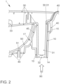
- Figure 2 shows a section of the trim arrangement 1 according to the invention in a sectional view perpendicular to its intended orientation when arranged in a vehicle door.
- the operating element 30 forms a projection 31, which in the embodiment shown is designed as a screw dome and has a substantially round inner cross-sectional area and a substantially round outer cross-sectional area.
- the projection 31 is designed in the direction of the fastening structure, which is not shown here.
- the contact surface 32 of the projection 31 rests against the fastening structure when arranged as intended.
- the trim element 40 is arranged on the outer side 33 of the control element 30 facing the fastening structure. It can be seen in the illustration that in the embodiment shown here the trim element 40 is part of a trim unit and is connected to an inner door trim element 50.
- the connection area 51 in which the connection between the trim element 40 and the inner door trim element 50 is realized, is designed here as a weld dome.
- the arrow indicates the direction from which a force 90 acts on the trim arrangement 1 in the event of a crash, in particular during a crash test, when it is arranged as intended in a vehicle.
- the force transmission element 10 is arranged on the lateral flanks of the projection 31.
- the surface which forms the first contact element 14 is arranged essentially in a plane with the contact surface 32.
- the surface which forms the second contact element 15 rests against an area of the cladding element 40.
- the force 90 is transmitted from the fastening structure to the cladding element 40 between the contact elements 14 and 15.
- the force transmission element 10 surrounds the projection essentially completely in the embodiment shown.
- the force transmission element 10 forms a locking connection 17 with the covering element 40. This connection serves to secure the device during transport and assembly and prevents the force transmission element 10 from being lost.
- FIG 3 shows the operating principle of the cladding system 1 according to the invention.
- the force 90 is shown, which acts from the outside on the fastening structure 20, so that it experiences a displacement upwards as shown in the illustration.
- the force 90 is transmitted at the contact surface 32 of the projection 31, which is surrounded by the force transmission element 10, both to the operating element 30 and, via the contact elements 14 and 15, to the cladding element 40.
- the operating element 30 and the cladding element 40 are thus displaced essentially by the same distance.
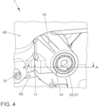
- Figure 4 shows a three-dimensional view of the panel arrangement 1 according to the invention. It can be seen that the force transmission element 10 is arranged on the projection 31 of the operating element and is fixed to the panel element 40, which is connected to the door interior panel element 50 at the connecting areas 51, by means of a snap-in connection 17.
- the fastening structure adjoins the contact surface 32 as intended.
- a fastening means such as a screw, is arranged in the central opening in the contact surface 32 to form the mechanical connection between the operating element and the fastening structure.
- the section marked here by AA corresponds to the illustration in Figure 2 .
- Figure 5 shows an embodiment of a door panel 100 of a vehicle door as an assembly in a three-dimensional view.
- the vehicle door shell into which the door panel shown is integrated is not shown.
- the side facing the viewer faces the vehicle interior when properly arranged in or on a door shell.
- the fastening structure 20 is provided in the form of a window lifter unit to which the operating element 30, which in the example is a pull handle of a vehicle door, is attached.
- the window lifter unit is connected to the door shell in the fully assembled vehicle door.
- a panel element 40 in the form of an armrest, which is only indicated here, is arranged between the fastening structure 20 and the operating element 30.
- the armrest is connected to the door interior panel element 50.
- the force transmission element 10 is arranged between the operating element 30 and the fastening structure 20.
- the view indicates that in the area of fastening of the operating element 30, the covering element 40 is arranged between the force transmission element 10 and the fastening structure 20 and is penetrated by the projection of the operating element 30.
- control element here the closing handle
- a control element cover in the finished vehicle.
- devices for controlling functions in or on the vehicle are arranged on the control element.
- Figure 6 shows the design of a door panel 100 according to Figure 5 viewed in three-dimensional view from the comparison to Figure 5 opposite direction.
- the rear side of the door panel can thus be seen, which lies inside the door when the vehicle door is fully assembled.
- the panel element 40 can be seen, which is connected to the inner door panel element 50 at the connecting areas 51.
- the connection implemented here is typically - but not necessarily - a welded connection.
- the panel element 40 is arranged in a nested manner in areas in front of and behind the inner door panel element 50.
- the panel element 40 and the inner door panel 50 can in principle also be designed in one piece, i.e. as a structural unit.
- the arrangement of the force transmission element 10 can also be seen.
- control element cannot be seen here, the projection of which penetrates through the covering element 40 and is surrounded by the power transmission element 10.
- the arrangement of the power transmission element 10 in this embodiment is shown in detail Figure 4 removable.
- cladding arrangement 1 power transmission element 10 stiffening element 11 first form element 12 second form element 13 first investment element 14 second investment element 15 collar 16 locking connection 17 fastening structure 20 control element 30 projection 31 contact surface 32 outside 33 cladding element 40 door interior trim element 50 connection area 51 Power 90 door panel 100
Landscapes
- Engineering & Computer Science (AREA)
- Mechanical Engineering (AREA)
- Vehicle Interior And Exterior Ornaments, Soundproofing, And Insulation (AREA)
Claims (10)
- Agencement de revêtement (1) destiné à l'équipement intérieur d'un véhicule automobile, en particulier à l'équipement intérieur d'une portière de véhicule automobile, comprenant un élément de commande (30) pouvant être relié mécaniquement à une structure de fixation (20), au moins un élément de revêtement (40) disposé au moins par sections sur un côté extérieur (33) de l'élément de commande (30), ainsi qu'au moins un élément de transmission de force (10), lequel est disposé sur un côté de l'élément de revêtement (40) opposé à l'élément de commande (30) et réalise au moins un premier élément d'appui (14) pour l'appui sur la structure de fixation (20) et au moins un second élément d'appui (15) pour l'appui sur l'élément de revêtement (40), en sorte que, lorsqu'une force (90) agit sur l'agencement de revêtement (1) avec au moins une composante perpendiculaire au côté de l'élément de revêtement (40) opposé à l'élément de commande (30) et lors d'un déplacement de l'élément de commande (30) provoqué par l'action de la force (90), la position relative de l'élément de revêtement (40) par rapport à l'élément de commande (30) reste au moins sensiblement inchangée.
- Agencement de revêtement (1) selon la revendication précédente, caractérisé en ce que l'élément de transmission de force (10) est disposé à proximité immédiate de la position de la liaison mécanique pouvant être réalisée entre l'élément de commande (30) et la structure de fixation (20), en sorte qu'une position de l'appui de l'élément de transmission de force (10) sur la structure de fixation (20) peut être réalisée, qui présente, par rapport à une position de la liaison mécanique entre l'élément de commande (30) et la structure de fixation (20), une distance qui est inférieure à la moitié de l'extension maximale de l'élément de transmission de force (10) dans un plan parallèle à celui réalisé par l'élément de revêtement (40).
- Agencement de revêtement (1) selon l'une des revendications précédentes, caractérisé en ce que l'élément de commande (30) réalise une saillie (31) traversant au moins partiellement l'élément de revêtement (40) afin de réaliser la liaison mécanique avec la structure de fixation (20).
- Agencement de revêtement (1) selon la revendication 3,
caractérisé en ce que l'élément de transmission de force (10) est réalisé au moins partiellement sous forme de profilé creux et entoure la saillie (31) au moins par sections, en sorte qu'une force (90) agissant sur l'agencement de revêtement (1) peut être transmise par l'élément de transmission de force (10) parallèlement à l'extension longitudinale de la saillie (31). - Agencement de revêtement (1) selon l'une des revendications précédentes, caractérisé en ce que l'élément de transmission de force (10) est fixé à l'élément de revêtement (40) par complémentarité de formes et/ou de force.
- Agencement de revêtement (1) selon l'une des revendications précédentes, caractérisé en ce que l'élément de transmission de force (10) présente au moins un élément de rigidification (11), en particulier une nervure de rigidification, dans le but d'augmenter au moins localement la rigidité de l'élément de transmission de force (10).
- Agencement de revêtement (1) selon l'une des revendications précédentes, caractérisé en ce que l'élément de transmission de force (10) présente au moins une zone à résistance réduite, en particulier un point destiné à la rupture, pour la déformation mécanique au moins partielle et/ou la rupture de l'élément de transmission de force (10) lors de l'application d'une force minimale définie sur l'agencement de revêtement (1) dans une direction définie, qui s'écarte sensiblement d'une direction d'application de force s'étendant perpendiculairement à l'élément de revêtement (40), afin d'empêcher ou de réduire une transmission de la force (90) agissant sur l'agencement de revêtement (1) à l'élément de revêtement (40).
- Agencement de revêtement (1) selon l'une des revendications précédentes, caractérisé en ce que l'élément de transmission de force (10) présente au moins un élément de verrouillage de forme (12, 13) afin de définir une position unique de l'élément de transmission de force (10) par rapport à l'élément de commande (30).
- Portière de véhicule automobile comprenant une structure brute de porte ainsi que, disposée sur celle-ci ou réalisée à partir de celle-ci, une structure de fixation (20) ainsi qu'un ensemble de revêtement (1) selon l'une des revendications précédentes, dans laquelle l'élément de commande (30) est relié mécaniquement à la structure de fixation (20).
- Véhicule automobile, en particulier voiture particulière, comprenant au moins un agencement de revêtement (1) selon l'une des revendications 1 à 8 et/ou au moins une portière de véhicule automobile selon la revendication 9.
Applications Claiming Priority (2)
| Application Number | Priority Date | Filing Date | Title |
|---|---|---|---|
| DE102019211376.1A DE102019211376A1 (de) | 2019-07-30 | 2019-07-30 | Verkleidungsanordnung zur Innenraumausstattung eines Kraftfahrzeugs, eine Kraftfahrzeugtür sowie Kraftfahrzeug |
| PCT/EP2020/071237 WO2021018877A1 (fr) | 2019-07-30 | 2020-07-28 | Revêtement destiné à l'aménagement intérieur d'un véhicule automobile, portière de véhicule automobile et véhicule automobile |
Publications (2)
| Publication Number | Publication Date |
|---|---|
| EP4003790A1 EP4003790A1 (fr) | 2022-06-01 |
| EP4003790B1 true EP4003790B1 (fr) | 2024-12-04 |
Family
ID=71846405
Family Applications (1)
| Application Number | Title | Priority Date | Filing Date |
|---|---|---|---|
| EP20747404.0A Active EP4003790B1 (fr) | 2019-07-30 | 2020-07-28 | Revêtement destiné à l'aménagement intérieur d'un véhicule automobile, portière de véhicule automobile et véhicule automobile |
Country Status (4)
| Country | Link |
|---|---|
| EP (1) | EP4003790B1 (fr) |
| CN (1) | CN114126903B (fr) |
| DE (1) | DE102019211376A1 (fr) |
| WO (1) | WO2021018877A1 (fr) |
Family Cites Families (14)
| Publication number | Priority date | Publication date | Assignee | Title |
|---|---|---|---|---|
| DE10048774B8 (de) * | 2000-09-29 | 2006-03-02 | Brose Fahrzeugteile Gmbh & Co. Kg, Coburg | Türelement und Verfahren zur Montage des Türelementes |
| DE102005053647B4 (de) * | 2005-11-10 | 2012-01-26 | Audi Ag | Befestigungsvorrichtung |
| JP5369520B2 (ja) * | 2008-07-14 | 2013-12-18 | トヨタ紡織株式会社 | 車両用ドアトリム |
| KR100986476B1 (ko) * | 2008-10-30 | 2010-10-08 | 현대자동차주식회사 | 차량용 내부 트림 |
| US8251434B2 (en) * | 2009-04-30 | 2012-08-28 | Ford Global Technologies, Llc | Fastener cover extension providing buckling path during side impact |
| US8424954B2 (en) * | 2011-04-01 | 2013-04-23 | Ford Global Technologies, Llc | Vehicle grab handle assembly |
| DE102011102302A1 (de) * | 2011-05-23 | 2012-01-12 | Daimler Ag | Befestigungsanordnung eines Innenverkleidungsteils an einem Verkleidungsträger eines Kraftwagens |
| AT513707B1 (de) * | 2012-12-05 | 2014-09-15 | Intier Automotive Eybl Gmbh Ebergassing & Co Ohg | Innenausstattungsteil, insbesondere Armauflage, für ein Kraftfahrzeug und Verfahren zur Montage/Demontage eines Innenausstattungsteils |
| JP6066301B2 (ja) * | 2013-02-18 | 2017-01-25 | スズキ株式会社 | 車両のドア構造 |
| JP6038724B2 (ja) * | 2013-05-13 | 2016-12-07 | 河西工業株式会社 | ドアトリムのアームレスト構造 |
| DE102013220409A1 (de) * | 2013-10-10 | 2015-04-16 | Zf Friedrichshafen Ag | Befestigungseinrichtung, Wählhebelgehäuse, Kraftübertragungselement, Schaltvorrichtung und Verfahren zum Befestigen einer Schaltvorrichtung |
| KR101501472B1 (ko) * | 2013-11-11 | 2015-03-11 | 한일이화 주식회사 | 차량용 도어의 풀 핸들 조립 구조 |
| US9156387B2 (en) * | 2014-02-17 | 2015-10-13 | Ford Global Technologies, Llc | Coupling structure for pull-cup and armrest assembly |
| JP6281407B2 (ja) * | 2014-05-14 | 2018-02-21 | トヨタ紡織株式会社 | 車両用内装材 |
-
2019
- 2019-07-30 DE DE102019211376.1A patent/DE102019211376A1/de not_active Withdrawn
-
2020
- 2020-07-28 CN CN202080053905.9A patent/CN114126903B/zh active Active
- 2020-07-28 EP EP20747404.0A patent/EP4003790B1/fr active Active
- 2020-07-28 WO PCT/EP2020/071237 patent/WO2021018877A1/fr not_active Ceased
Also Published As
| Publication number | Publication date |
|---|---|
| CN114126903B (zh) | 2024-10-01 |
| WO2021018877A1 (fr) | 2021-02-04 |
| CN114126903A (zh) | 2022-03-01 |
| EP4003790A1 (fr) | 2022-06-01 |
| DE102019211376A1 (de) | 2021-02-04 |
Similar Documents
| Publication | Publication Date | Title |
|---|---|---|
| DE19748970B4 (de) | Integrale Türinnenverstärkung | |
| EP1964715B1 (fr) | Dispositif d'adaptateur pour une poignée | |
| EP2040970B1 (fr) | Dispositif de fixation d'une colonne de direction d'un véhicule automobile | |
| WO2016156178A1 (fr) | Dispositif adaptateur pour un siège de véhicule et siège de véhicule | |
| WO2023088660A1 (fr) | Structure de paroi latérale pour une carrosserie d'un véhicule motorisé | |
| WO2007144131A1 (fr) | Écrou de broche pour dispositifs de positionnement de véhicule automobile | |
| DE102015100195B4 (de) | Befestigungsanordnung eines Seitenwandelements an einem inneren Strukturelement einer Karosserie eines Personenkraftwagens | |
| EP4399376A1 (fr) | Verrou de véhicule automobile, en particulier verrou de portière de véhicule automobile | |
| EP4003790B1 (fr) | Revêtement destiné à l'aménagement intérieur d'un véhicule automobile, portière de véhicule automobile et véhicule automobile | |
| EP1609703B1 (fr) | Poutre transversale | |
| DE102005011834B4 (de) | Seitlicher Dachrahmen für ein Kraftfahrzeug | |
| DE19910086A1 (de) | Kraftfahrzeug mit Fahrzeugsitz | |
| DE102009012237B4 (de) | Karosserie für ein Kraftfahrzeug | |
| EP4412888B1 (fr) | Ensemble de répartition de charge dans un véhicule | |
| DE102018208800B4 (de) | Verbindungsanordnung mit einem Dachprofil und einem Dachgepäckträger | |
| DE102004029278B4 (de) | Tragstruktur für ein Kraftfahrzeug | |
| DE102017220987B4 (de) | Strukturbauteil für die Karosserie eines Fahrzeugs | |
| DE10058998C1 (de) | Stoßfängereinheit eines Kraftfahrzeuges | |
| DE102009042633B4 (de) | Kraftfahrzeug mit Crashbox | |
| DE102015012142B3 (de) | Fahrzeugkarosserie eines Kraftfahrzeugs | |
| DE102020214641A1 (de) | Verkleidungsanordnung zur Innenraumausstattung eines Kraftfahrzeugs, eine Kraftfahrzeugtür sowie Kraftfahrzeug | |
| WO2025073731A1 (fr) | Unité structurale pour une carrosserie de véhicule, véhicule automobile et procédé de production d'une carrosserie de véhicule | |
| DE10356465B3 (de) | Kraftfahrzeugtür mit einem Seitenaufprallträger und einem Türkörper | |
| EP1840008B1 (fr) | Dispositif destiné à la liaison de composants d'une carrosserie de véhicule automobile | |
| DE19840524A1 (de) | Boden-Seitenschweller für die Karosserie eines Kraftfahrzeugs |
Legal Events
| Date | Code | Title | Description |
|---|---|---|---|
| STAA | Information on the status of an ep patent application or granted ep patent |
Free format text: STATUS: UNKNOWN |
|
| STAA | Information on the status of an ep patent application or granted ep patent |
Free format text: STATUS: THE INTERNATIONAL PUBLICATION HAS BEEN MADE |
|
| PUAI | Public reference made under article 153(3) epc to a published international application that has entered the european phase |
Free format text: ORIGINAL CODE: 0009012 |
|
| STAA | Information on the status of an ep patent application or granted ep patent |
Free format text: STATUS: REQUEST FOR EXAMINATION WAS MADE |
|
| 17P | Request for examination filed |
Effective date: 20220228 |
|
| AK | Designated contracting states |
Kind code of ref document: A1 Designated state(s): AL AT BE BG CH CY CZ DE DK EE ES FI FR GB GR HR HU IE IS IT LI LT LU LV MC MK MT NL NO PL PT RO RS SE SI SK SM TR |
|
| DAV | Request for validation of the european patent (deleted) | ||
| DAX | Request for extension of the european patent (deleted) | ||
| GRAP | Despatch of communication of intention to grant a patent |
Free format text: ORIGINAL CODE: EPIDOSNIGR1 |
|
| STAA | Information on the status of an ep patent application or granted ep patent |
Free format text: STATUS: GRANT OF PATENT IS INTENDED |
|
| INTG | Intention to grant announced |
Effective date: 20240903 |
|
| GRAS | Grant fee paid |
Free format text: ORIGINAL CODE: EPIDOSNIGR3 |
|
| GRAA | (expected) grant |
Free format text: ORIGINAL CODE: 0009210 |
|
| STAA | Information on the status of an ep patent application or granted ep patent |
Free format text: STATUS: THE PATENT HAS BEEN GRANTED |
|
| AK | Designated contracting states |
Kind code of ref document: B1 Designated state(s): AL AT BE BG CH CY CZ DE DK EE ES FI FR GB GR HR HU IE IS IT LI LT LU LV MC MK MT NL NO PL PT RO RS SE SI SK SM TR |
|
| REG | Reference to a national code |
Ref country code: CH Ref legal event code: EP |
|
| REG | Reference to a national code |
Ref country code: DE Ref legal event code: R096 Ref document number: 502020009900 Country of ref document: DE |
|
| REG | Reference to a national code |
Ref country code: IE Ref legal event code: FG4D Free format text: LANGUAGE OF EP DOCUMENT: GERMAN |
|
| REG | Reference to a national code |
Ref country code: LT Ref legal event code: MG9D |
|
| REG | Reference to a national code |
Ref country code: NL Ref legal event code: MP Effective date: 20241204 |
|
| PG25 | Lapsed in a contracting state [announced via postgrant information from national office to epo] |
Ref country code: HR Free format text: LAPSE BECAUSE OF FAILURE TO SUBMIT A TRANSLATION OF THE DESCRIPTION OR TO PAY THE FEE WITHIN THE PRESCRIBED TIME-LIMIT Effective date: 20241204 |
|
| PG25 | Lapsed in a contracting state [announced via postgrant information from national office to epo] |
Ref country code: FI Free format text: LAPSE BECAUSE OF FAILURE TO SUBMIT A TRANSLATION OF THE DESCRIPTION OR TO PAY THE FEE WITHIN THE PRESCRIBED TIME-LIMIT Effective date: 20241204 |
|
| PG25 | Lapsed in a contracting state [announced via postgrant information from national office to epo] |
Ref country code: BG Free format text: LAPSE BECAUSE OF FAILURE TO SUBMIT A TRANSLATION OF THE DESCRIPTION OR TO PAY THE FEE WITHIN THE PRESCRIBED TIME-LIMIT Effective date: 20241204 |
|
| PG25 | Lapsed in a contracting state [announced via postgrant information from national office to epo] |
Ref country code: ES Free format text: LAPSE BECAUSE OF FAILURE TO SUBMIT A TRANSLATION OF THE DESCRIPTION OR TO PAY THE FEE WITHIN THE PRESCRIBED TIME-LIMIT Effective date: 20241204 |
|
| PG25 | Lapsed in a contracting state [announced via postgrant information from national office to epo] |
Ref country code: NO Free format text: LAPSE BECAUSE OF FAILURE TO SUBMIT A TRANSLATION OF THE DESCRIPTION OR TO PAY THE FEE WITHIN THE PRESCRIBED TIME-LIMIT Effective date: 20250304 |
|
| PG25 | Lapsed in a contracting state [announced via postgrant information from national office to epo] |
Ref country code: LV Free format text: LAPSE BECAUSE OF FAILURE TO SUBMIT A TRANSLATION OF THE DESCRIPTION OR TO PAY THE FEE WITHIN THE PRESCRIBED TIME-LIMIT Effective date: 20241204 Ref country code: GR Free format text: LAPSE BECAUSE OF FAILURE TO SUBMIT A TRANSLATION OF THE DESCRIPTION OR TO PAY THE FEE WITHIN THE PRESCRIBED TIME-LIMIT Effective date: 20250305 |
|
| PG25 | Lapsed in a contracting state [announced via postgrant information from national office to epo] |
Ref country code: RS Free format text: LAPSE BECAUSE OF FAILURE TO SUBMIT A TRANSLATION OF THE DESCRIPTION OR TO PAY THE FEE WITHIN THE PRESCRIBED TIME-LIMIT Effective date: 20250304 |
|
| PG25 | Lapsed in a contracting state [announced via postgrant information from national office to epo] |
Ref country code: NL Free format text: LAPSE BECAUSE OF FAILURE TO SUBMIT A TRANSLATION OF THE DESCRIPTION OR TO PAY THE FEE WITHIN THE PRESCRIBED TIME-LIMIT Effective date: 20241204 |
|
| PG25 | Lapsed in a contracting state [announced via postgrant information from national office to epo] |
Ref country code: SM Free format text: LAPSE BECAUSE OF FAILURE TO SUBMIT A TRANSLATION OF THE DESCRIPTION OR TO PAY THE FEE WITHIN THE PRESCRIBED TIME-LIMIT Effective date: 20241204 |
|
| PG25 | Lapsed in a contracting state [announced via postgrant information from national office to epo] |
Ref country code: PL Free format text: LAPSE BECAUSE OF FAILURE TO SUBMIT A TRANSLATION OF THE DESCRIPTION OR TO PAY THE FEE WITHIN THE PRESCRIBED TIME-LIMIT Effective date: 20241204 |
|
| PG25 | Lapsed in a contracting state [announced via postgrant information from national office to epo] |
Ref country code: IS Free format text: LAPSE BECAUSE OF FAILURE TO SUBMIT A TRANSLATION OF THE DESCRIPTION OR TO PAY THE FEE WITHIN THE PRESCRIBED TIME-LIMIT Effective date: 20250404 |
|
| PG25 | Lapsed in a contracting state [announced via postgrant information from national office to epo] |
Ref country code: PT Free format text: LAPSE BECAUSE OF FAILURE TO SUBMIT A TRANSLATION OF THE DESCRIPTION OR TO PAY THE FEE WITHIN THE PRESCRIBED TIME-LIMIT Effective date: 20250404 |
|
| PG25 | Lapsed in a contracting state [announced via postgrant information from national office to epo] |
Ref country code: EE Free format text: LAPSE BECAUSE OF FAILURE TO SUBMIT A TRANSLATION OF THE DESCRIPTION OR TO PAY THE FEE WITHIN THE PRESCRIBED TIME-LIMIT Effective date: 20241204 |
|
| PG25 | Lapsed in a contracting state [announced via postgrant information from national office to epo] |
Ref country code: RO Free format text: LAPSE BECAUSE OF FAILURE TO SUBMIT A TRANSLATION OF THE DESCRIPTION OR TO PAY THE FEE WITHIN THE PRESCRIBED TIME-LIMIT Effective date: 20241204 |
|
| PG25 | Lapsed in a contracting state [announced via postgrant information from national office to epo] |
Ref country code: SK Free format text: LAPSE BECAUSE OF FAILURE TO SUBMIT A TRANSLATION OF THE DESCRIPTION OR TO PAY THE FEE WITHIN THE PRESCRIBED TIME-LIMIT Effective date: 20241204 |
|
| PG25 | Lapsed in a contracting state [announced via postgrant information from national office to epo] |
Ref country code: CZ Free format text: LAPSE BECAUSE OF FAILURE TO SUBMIT A TRANSLATION OF THE DESCRIPTION OR TO PAY THE FEE WITHIN THE PRESCRIBED TIME-LIMIT Effective date: 20241204 |
|
| PG25 | Lapsed in a contracting state [announced via postgrant information from national office to epo] |
Ref country code: IT Free format text: LAPSE BECAUSE OF FAILURE TO SUBMIT A TRANSLATION OF THE DESCRIPTION OR TO PAY THE FEE WITHIN THE PRESCRIBED TIME-LIMIT Effective date: 20241204 |
|
| REG | Reference to a national code |
Ref country code: DE Ref legal event code: R097 Ref document number: 502020009900 Country of ref document: DE |
|
| PG25 | Lapsed in a contracting state [announced via postgrant information from national office to epo] |
Ref country code: SE Free format text: LAPSE BECAUSE OF FAILURE TO SUBMIT A TRANSLATION OF THE DESCRIPTION OR TO PAY THE FEE WITHIN THE PRESCRIBED TIME-LIMIT Effective date: 20241204 |
|
| PG25 | Lapsed in a contracting state [announced via postgrant information from national office to epo] |
Ref country code: DK Free format text: LAPSE BECAUSE OF FAILURE TO SUBMIT A TRANSLATION OF THE DESCRIPTION OR TO PAY THE FEE WITHIN THE PRESCRIBED TIME-LIMIT Effective date: 20241204 |
|
| PGFP | Annual fee paid to national office [announced via postgrant information from national office to epo] |
Ref country code: DE Payment date: 20250731 Year of fee payment: 6 |
|
| PLBE | No opposition filed within time limit |
Free format text: ORIGINAL CODE: 0009261 |
|
| STAA | Information on the status of an ep patent application or granted ep patent |
Free format text: STATUS: NO OPPOSITION FILED WITHIN TIME LIMIT |
|
| REG | Reference to a national code |
Ref country code: CH Ref legal event code: L10 Free format text: ST27 STATUS EVENT CODE: U-0-0-L10-L00 (AS PROVIDED BY THE NATIONAL OFFICE) Effective date: 20251015 |
|
| PGFP | Annual fee paid to national office [announced via postgrant information from national office to epo] |
Ref country code: GB Payment date: 20250722 Year of fee payment: 6 |
|
| PGFP | Annual fee paid to national office [announced via postgrant information from national office to epo] |
Ref country code: FR Payment date: 20250725 Year of fee payment: 6 |
|
| 26N | No opposition filed |
Effective date: 20250905 |
|
| REG | Reference to a national code |
Ref country code: CH Ref legal event code: H13 Free format text: ST27 STATUS EVENT CODE: U-0-0-H10-H13 (AS PROVIDED BY THE NATIONAL OFFICE) Effective date: 20260224 |
|
| PG25 | Lapsed in a contracting state [announced via postgrant information from national office to epo] |
Ref country code: LU Free format text: LAPSE BECAUSE OF NON-PAYMENT OF DUE FEES Effective date: 20250728 |
|
| REG | Reference to a national code |
Ref country code: BE Ref legal event code: MM Effective date: 20250731 |
|
| PG25 | Lapsed in a contracting state [announced via postgrant information from national office to epo] |
Ref country code: BE Free format text: LAPSE BECAUSE OF NON-PAYMENT OF DUE FEES Effective date: 20250731 |
|
| PG25 | Lapsed in a contracting state [announced via postgrant information from national office to epo] |
Ref country code: CH Free format text: LAPSE BECAUSE OF NON-PAYMENT OF DUE FEES Effective date: 20250731 |