EP1964775A2 - Dispositif de mélange pour installation de climatisation d'avion - Google Patents
Dispositif de mélange pour installation de climatisation d'avion Download PDFInfo
- Publication number
- EP1964775A2 EP1964775A2 EP20080003811 EP08003811A EP1964775A2 EP 1964775 A2 EP1964775 A2 EP 1964775A2 EP 20080003811 EP20080003811 EP 20080003811 EP 08003811 A EP08003811 A EP 08003811A EP 1964775 A2 EP1964775 A2 EP 1964775A2
- Authority
- EP
- European Patent Office
- Prior art keywords
- air
- mixing device
- aircraft
- pockets
- printed area
- Prior art date
- Legal status (The legal status is an assumption and is not a legal conclusion. Google has not performed a legal analysis and makes no representation as to the accuracy of the status listed.)
- Granted
Links
Images


Classifications
-
- B—PERFORMING OPERATIONS; TRANSPORTING
- B64—AIRCRAFT; AVIATION; COSMONAUTICS
- B64D—EQUIPMENT FOR FITTING IN OR TO AIRCRAFT; FLIGHT SUITS; PARACHUTES; ARRANGEMENT OR MOUNTING OF POWER PLANTS OR PROPULSION TRANSMISSIONS IN AIRCRAFT
- B64D13/00—Arrangements or adaptations of air-treatment apparatus for aircraft crew or passengers, or freight space
-
- F—MECHANICAL ENGINEERING; LIGHTING; HEATING; WEAPONS; BLASTING
- F24—HEATING; RANGES; VENTILATING
- F24F—AIR-CONDITIONING; AIR-HUMIDIFICATION; VENTILATION; USE OF AIR CURRENTS FOR SCREENING
- F24F13/00—Details common to, or for air-conditioning, air-humidification, ventilation or use of air currents for screening
- F24F13/02—Ducting arrangements
- F24F13/04—Air-mixing units
-
- Y—GENERAL TAGGING OF NEW TECHNOLOGICAL DEVELOPMENTS; GENERAL TAGGING OF CROSS-SECTIONAL TECHNOLOGIES SPANNING OVER SEVERAL SECTIONS OF THE IPC; TECHNICAL SUBJECTS COVERED BY FORMER USPC CROSS-REFERENCE ART COLLECTIONS [XRACs] AND DIGESTS
- Y02—TECHNOLOGIES OR APPLICATIONS FOR MITIGATION OR ADAPTATION AGAINST CLIMATE CHANGE
- Y02T—CLIMATE CHANGE MITIGATION TECHNOLOGIES RELATED TO TRANSPORTATION
- Y02T50/00—Aeronautics or air transport
- Y02T50/40—Weight reduction
-
- Y—GENERAL TAGGING OF NEW TECHNOLOGICAL DEVELOPMENTS; GENERAL TAGGING OF CROSS-SECTIONAL TECHNOLOGIES SPANNING OVER SEVERAL SECTIONS OF THE IPC; TECHNICAL SUBJECTS COVERED BY FORMER USPC CROSS-REFERENCE ART COLLECTIONS [XRACs] AND DIGESTS
- Y10—TECHNICAL SUBJECTS COVERED BY FORMER USPC
- Y10T—TECHNICAL SUBJECTS COVERED BY FORMER US CLASSIFICATION
- Y10T137/00—Fluid handling
- Y10T137/0318—Processes
- Y10T137/0324—With control of flow by a condition or characteristic of a fluid
- Y10T137/0329—Mixing of plural fluids of diverse characteristics or conditions
-
- Y—GENERAL TAGGING OF NEW TECHNOLOGICAL DEVELOPMENTS; GENERAL TAGGING OF CROSS-SECTIONAL TECHNOLOGIES SPANNING OVER SEVERAL SECTIONS OF THE IPC; TECHNICAL SUBJECTS COVERED BY FORMER USPC CROSS-REFERENCE ART COLLECTIONS [XRACs] AND DIGESTS
- Y10—TECHNICAL SUBJECTS COVERED BY FORMER USPC
- Y10T—TECHNICAL SUBJECTS COVERED BY FORMER US CLASSIFICATION
- Y10T137/00—Fluid handling
- Y10T137/1842—Ambient condition change responsive
- Y10T137/1939—Atmospheric
- Y10T137/2012—Pressure
-
- Y—GENERAL TAGGING OF NEW TECHNOLOGICAL DEVELOPMENTS; GENERAL TAGGING OF CROSS-SECTIONAL TECHNOLOGIES SPANNING OVER SEVERAL SECTIONS OF THE IPC; TECHNICAL SUBJECTS COVERED BY FORMER USPC CROSS-REFERENCE ART COLLECTIONS [XRACs] AND DIGESTS
- Y10—TECHNICAL SUBJECTS COVERED BY FORMER USPC
- Y10T—TECHNICAL SUBJECTS COVERED BY FORMER US CLASSIFICATION
- Y10T137/00—Fluid handling
- Y10T137/7722—Line condition change responsive valves
-
- Y—GENERAL TAGGING OF NEW TECHNOLOGICAL DEVELOPMENTS; GENERAL TAGGING OF CROSS-SECTIONAL TECHNOLOGIES SPANNING OVER SEVERAL SECTIONS OF THE IPC; TECHNICAL SUBJECTS COVERED BY FORMER USPC CROSS-REFERENCE ART COLLECTIONS [XRACs] AND DIGESTS
- Y10—TECHNICAL SUBJECTS COVERED BY FORMER USPC
- Y10T—TECHNICAL SUBJECTS COVERED BY FORMER US CLASSIFICATION
- Y10T137/00—Fluid handling
- Y10T137/7722—Line condition change responsive valves
- Y10T137/7837—Direct response valves [i.e., check valve type]
-
- Y—GENERAL TAGGING OF NEW TECHNOLOGICAL DEVELOPMENTS; GENERAL TAGGING OF CROSS-SECTIONAL TECHNOLOGIES SPANNING OVER SEVERAL SECTIONS OF THE IPC; TECHNICAL SUBJECTS COVERED BY FORMER USPC CROSS-REFERENCE ART COLLECTIONS [XRACs] AND DIGESTS
- Y10—TECHNICAL SUBJECTS COVERED BY FORMER USPC
- Y10T—TECHNICAL SUBJECTS COVERED BY FORMER US CLASSIFICATION
- Y10T137/00—Fluid handling
- Y10T137/8593—Systems
- Y10T137/87571—Multiple inlet with single outlet
Definitions
- the invention relates to a mixing device for an aircraft air conditioning system with a supply line for fresh air from the air conditioner, with a second supply line for recirculated air from a printed area of the aircraft and with a discharge line for supplying mixed air in the printed area of the aircraft.
- Aircraft air conditioners serve to provide conditioned air for the various areas of the aircraft, for example for the aircraft cabin or for the cockpit.
- the invention now relates in particular to a component for mixing and / or splitting various air streams.
- Fresh air from the air conditioning system is mixed with air from the aircraft cabin and fed back into the cabin via a distribution system.
- the premix of cold fresh air from the air conditioning system with warm recirculation from the cabin is done as based on the FIG. 1 is shown, conventionally so far in the unprinted area in the aircraft.
- the warm circulating air from the cabin is guided through the so-called pressure bulkhead into the unprinted area.
- the mixed, ice-free air is returned to the cabin via a non-return flap.
- the recirculation line is closed in Druckspant by another safety valve.
- the non-return valve is connected downstream of the mixer, so that the non-return valve is acted upon compared to the cold fresh air warmer mixed air and thus remains free of ice.
- Object of the present invention is to develop a generic aircraft air conditioning system such that this can be performed with fewer components and thereby cheaper and easier.
- a mixing apparatus for an aircraft air conditioner having a fresh air supply duct from the air conditioner, a second supply duct for supplied air from a printed area of the aircraft, and a discharge duct for supplying mixed air to the printed area of the aircraft are provided a check valve is integrated.
- the mixing device according to the design according to the not previously published DE 10 2007 002 138.2 consist of pockets arranged one above the other in the flow cross-section, partly having a free cross-section for directing the fresh air from the air conditioner into the discharge duct for supplying mixed air to the printed area of the aircraft and the other part having a diagonal partition to return returned air from the printed area of the aircraft into the discharge line for supplying mixed air into the printed area of the aircraft.
- differently constructed bags can be arranged alternately one above the other in several layers.
- 10 to 20 pockets are to be arranged one above the other in a mixing device.
- hot process air can also be diverted from the air conditioning system and fed to the mixing device, thereby preventing icing with even greater safety.
- the pockets may have a substantially triangular base.
- the check valve is formed by the fact that the outlet slots formed by the pockets intermediate spaces for the coming of the air conditioning cold fresh air via flaps are closed.
- the flaps can be pivotally hinged hanging down at the edge of the outlet slots. This makes it possible for the flaps to be open in the warm circulating air flow and thus to remain free of ice. Only in case of failure, the cold fresh air path in the mixer is closed by the Zu fallenden flaps.
- a mixing device 10 which has an integrated non-return valve 12.
- the mixing device 10 is arranged here in the printed area of the aircraft, not shown. From the unprinted area cold fresh air is supplied to the mixing device 10. From the printed area, hot circulating air is also supplied, for example, from the aircraft cabin to the mixing device within the printed area and mixed with the cold fresh air. The corresponding mixed air also exits from the mixing device 10 in the printed area.
- the non-return valve 12 arranged according to the invention in the mixing device 10 prevents the pressure drop in the printed area when a line breaks or leaks in the unprinted area.
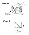
- FIGS. 3 to 6 Based on FIGS. 3 to 6 a structural design of the mixing device according to the invention is shown. This corresponds essentially to the structure of DE 10 2007 002 138.2 the same applicant, to which reference is additionally made.
- the mixing device 10 consists here of stacked substantially triangular running pockets 20 which are arranged in the flow cross-section of the substantially box-shaped mixer 10 to form gaps 22 are.
- the functions of the pockets 20 is that the warm circulating air entering from the printed area, ie the aircraft cabin, is deflected by 90 ° and exits the mixed air outlet 14 again as part of the mixed air.
- this recirculated air which is diverted by 90 °, mixes with the fresh air flowing through the mixing device 10 in the region of the intermediate spaces 22 between the pockets 20.
- the substantially triangular pocket 20 is shown with its rear wall 24.
- the circulating air flow or the fresh air flow is indicated by the corresponding arrows.
- From the sectional view AA in FIG. 5 shows that 12 individual flaps 26 is disposed in the region of the spaces between the pockets 20 as a check valve.
- the cold fresh air coming from the unprinted area flows through these intermediate spaces 22.
- the flaps, which are hinged to the corresponding pockets 20 fall down due to their force of gravity and close the passage slots 22, which constitute the connection between the unprinted and the printed part. In this way, these flaps, which form in FIG. 6 are shown in the closed position, a simply constructed check valve.
- flaps In the present embodiment, four flaps are shown. However, it is also possible to use other embodiments with fewer flaps, for example one or two flaps or even more flaps, in the context of the present invention.
- a fresh air connection is shown. Instead of a fresh air connection but can also be provided two or more connections. In the same way, instead of the one recirculation connection shown here, two or more connections for the circulating air may also be provided. Finally, additional connections for tapping fresh air may be present. Also, the flaps 26 can not only with circulating air, but also with not shown in here manner hot fresh air, d. H. so-called trim air, are heated from the air conditioning.
Landscapes
- Engineering & Computer Science (AREA)
- Health & Medical Sciences (AREA)
- General Health & Medical Sciences (AREA)
- Pulmonology (AREA)
- Aviation & Aerospace Engineering (AREA)
- Chemical & Material Sciences (AREA)
- Combustion & Propulsion (AREA)
- Mechanical Engineering (AREA)
- General Engineering & Computer Science (AREA)
- Air-Conditioning For Vehicles (AREA)
- Duct Arrangements (AREA)
Applications Claiming Priority (1)
| Application Number | Priority Date | Filing Date | Title |
|---|---|---|---|
| DE200710010268 DE102007010268A1 (de) | 2007-03-02 | 2007-03-02 | Mischvorrichtung für Flugzeugklimaanlage |
Publications (3)
| Publication Number | Publication Date |
|---|---|
| EP1964775A2 true EP1964775A2 (fr) | 2008-09-03 |
| EP1964775A3 EP1964775A3 (fr) | 2012-03-07 |
| EP1964775B1 EP1964775B1 (fr) | 2014-04-16 |
Family
ID=39434146
Family Applications (1)
| Application Number | Title | Priority Date | Filing Date |
|---|---|---|---|
| EP20080003811 Active EP1964775B1 (fr) | 2007-03-02 | 2008-02-29 | Dispositif de mélange pour installation de climatisation d'avion |
Country Status (3)
| Country | Link |
|---|---|
| US (1) | US8789766B2 (fr) |
| EP (1) | EP1964775B1 (fr) |
| DE (1) | DE102007010268A1 (fr) |
Cited By (2)
| Publication number | Priority date | Publication date | Assignee | Title |
|---|---|---|---|---|
| WO2013092727A1 (fr) * | 2011-12-20 | 2013-06-27 | Airbus Operations Gmbh | Dispositif de mélange avec risque réduit de givrage |
| FR3028241A1 (fr) * | 2014-11-06 | 2016-05-13 | Airbus Operations Sas | Aeronef dote d'un systeme de conditionnement d'air ameliore |
Families Citing this family (11)
| Publication number | Priority date | Publication date | Assignee | Title |
|---|---|---|---|---|
| DE102008058451B4 (de) * | 2008-11-21 | 2010-11-18 | Airbus Deutschland Gmbh | Verfahren und System zur Notbelüftung einer Flugzeugkabine im Fall eines Lecks im Bereich eines Luftmischers |
| WO2011124390A1 (fr) * | 2010-04-09 | 2011-10-13 | Airbus Operations Gmbh | Ensemble mélangeur pour système de conditionnement d'air d'avion |
| US9151539B2 (en) * | 2011-04-07 | 2015-10-06 | Hamilton Sundstrand Corporation | Heat exchanger having a core angled between two headers |
| DE102011078248A1 (de) * | 2011-06-28 | 2013-01-03 | Behr Gmbh & Co. Kg | Mischer zur Mischung von Luftströmen |
| CN104251547B (zh) * | 2014-09-23 | 2017-03-22 | 中国商用飞机有限责任公司 | 用于飞机空调系统的除水装置 |
| US10023317B2 (en) * | 2015-06-23 | 2018-07-17 | The Boeing Company | Flight deck takeoff duct and trim air mix muff |
| US10859286B2 (en) * | 2015-11-30 | 2020-12-08 | Blender Products, Inc. | Combined economizer and mixer for air handling unit |
| US10605481B2 (en) | 2016-03-24 | 2020-03-31 | Gregory Mark Huseman | Systems and methods for replaceable multiple filter units |
| US10809021B2 (en) * | 2016-12-08 | 2020-10-20 | Hamilton Sunstrand Corporation | Heat exchanger with sliding aperture valve |
| US20190255912A1 (en) * | 2018-02-19 | 2019-08-22 | Ford Global Technologies, Llc | Cabin heating system with sealed heat transfer loop |
| FI129583B (fi) * | 2021-04-29 | 2022-05-13 | Napalmi Tietotekniikka Oy | Puhallin |
Citations (1)
| Publication number | Priority date | Publication date | Assignee | Title |
|---|---|---|---|---|
| US6971607B2 (en) | 2003-09-22 | 2005-12-06 | Hamilton Sundstrand | Aircraft air conditioning system mixer with corrugations |
Family Cites Families (44)
| Publication number | Priority date | Publication date | Assignee | Title |
|---|---|---|---|---|
| US76717A (en) * | 1868-04-14 | Improvement in ventilators | ||
| US1300416A (en) * | 1918-02-05 | 1919-04-15 | Joseph Koenig | Heating apparatus. |
| US2085761A (en) * | 1933-02-15 | 1937-07-06 | Milo Ab | Aircraft power plant |
| US2370035A (en) * | 1942-11-16 | 1945-02-20 | Stewart Warner Corp | Heating system |
| US2400617A (en) * | 1943-04-17 | 1946-05-21 | L J Wing Mfg Co | Heating means |
| US2465728A (en) * | 1944-08-16 | 1949-03-29 | Cons Vultee Aircraft Corp | Air scoop |
| US2521866A (en) * | 1946-09-09 | 1950-09-12 | Oran W Ott | Air-heating furnace with automatically controlled air by-pass for preventing condensation |
| US2628482A (en) * | 1950-08-26 | 1953-02-17 | Garrett Corp | Air conditioning means for enclosures |
| US2674177A (en) * | 1951-08-04 | 1954-04-06 | C A Olson Mfg Company | Recirculating entrainment device for forced air heating systems |
| US2884228A (en) * | 1956-01-03 | 1959-04-28 | Buffalo Forge Co | Air conditioning units |
| FR1261312A (fr) * | 1960-04-05 | 1961-05-19 | Saint Gobain | Procédé et dispositif statique de mélange de fluides |
| US3187768A (en) * | 1960-08-10 | 1965-06-08 | Buensod Stacey Corp | Flow control |
| US3203473A (en) * | 1960-10-05 | 1965-08-31 | Lockheed Aircraft Corp | Aircraft heating system |
| FR1281715A (fr) * | 1961-02-24 | 1962-01-12 | British Oxygen Co Ltd | Dispositif d'alimentation en oxygène sur avion |
| US3212424A (en) * | 1963-05-14 | 1965-10-19 | Trane Co | Fluid control device |
| US3405758A (en) * | 1966-03-16 | 1968-10-15 | Itt | Air mixing apparatus with auxiliary air outlet |
| US3911804A (en) * | 1974-05-20 | 1975-10-14 | William K Y Tao | Air mixing device |
| US4203485A (en) * | 1976-12-17 | 1980-05-20 | Aronoff Melvin S | Multizone air terminal |
| US4328926A (en) * | 1978-05-19 | 1982-05-11 | Hall Jr William K | Air-handling unit |
| US4301833A (en) * | 1979-10-05 | 1981-11-24 | Donald Iii Robert A | Flow responsive safety valve |
| US4350100A (en) * | 1979-11-13 | 1982-09-21 | James Howden Australia Pty. Limited | Air infiltration and mixing device |
| US4470342A (en) * | 1980-11-07 | 1984-09-11 | Hall Jr William K | Air-handling unit |
| JPS60209318A (ja) * | 1984-04-04 | 1985-10-21 | Nissan Motor Co Ltd | 自動車用空気調和装置のヒ−タユニツト |
| JPS61195286A (ja) * | 1985-02-22 | 1986-08-29 | Matsushita Electric Works Ltd | 換気装置 |
| NL8602338A (nl) * | 1986-09-16 | 1988-04-18 | Hoogovens Groep Bv | Gasmenger. |
| DE3715133A1 (de) * | 1987-05-07 | 1988-11-24 | Ahlbrandt Andreas | Mischkammer |
| DE8711340U1 (de) * | 1987-08-18 | 1987-10-15 | Hansa Ventilatoren u. Maschinenbau Neumann GmbH & Co KG, 2915 Saterland | Luftmischeinrichtung |
| DE3817215C1 (en) * | 1988-05-17 | 1989-07-13 | Wolf Klimatechnik Gmbh, 8302 Mainburg, De | Mixing-air part for a mixing chamber of a ventilation or air-conditioning installation |
| US5031514A (en) * | 1989-09-08 | 1991-07-16 | Kice John E | Apparatus and method for controlling the mixing of atmospheric air with return air from a building |
| US5463967A (en) * | 1994-07-21 | 1995-11-07 | Airflow Sciences Corporation | Static mixer device for improving homogeneity of a characteristic of a mixture stream created from fluid streams separately entering the device |
| US5634964A (en) * | 1995-02-13 | 1997-06-03 | United Technologies Corporation | Air mixer with water separator |
| US6006142A (en) * | 1997-07-14 | 1999-12-21 | Seem; John E. | Environmental control system and method |
| DE19963280C1 (de) * | 1999-12-27 | 2001-08-23 | Liebherr Aerospace Gmbh | Klimatisierungssystem für Flugzeugkabinen |
| US6346041B1 (en) * | 2000-02-04 | 2002-02-12 | Cox Engineering Company, Inc. | Economizer |
| JP4396014B2 (ja) * | 2000-06-06 | 2010-01-13 | 株式会社デンソー | 空調装置 |
| US6401473B1 (en) * | 2000-07-31 | 2002-06-11 | The Boeing Company | Aircraft air conditioning system and method |
| US6318096B1 (en) * | 2000-09-05 | 2001-11-20 | The University Of Akron | Single sensor mixing box and methodology for preventing air handling unit coil freeze-up |
| US6547433B2 (en) * | 2001-01-05 | 2003-04-15 | M & I Heat Transfer Products, Ltd. | Air mixing device having series of parallel airflow passages |
| FR2839948B1 (fr) * | 2002-05-22 | 2004-12-17 | Airbus France | Echangeur pour circuit de conditionnement d'air d'aeronef et ensemble de propulsion integrant un tel echangeur |
| KR100617078B1 (ko) * | 2005-02-07 | 2006-08-30 | 엘지전자 주식회사 | 콤팩트형 환기시스템 |
| DE202005005902U1 (de) * | 2005-04-07 | 2005-06-16 | M + W Zander Facility Engineering Gmbh | Gerät zur Handhabung und/oder Behandlung von Erzeugnissen |
| DE102005046728A1 (de) * | 2005-09-29 | 2007-04-12 | Airbus Deutschland Gmbh | Geräuscharme Durchflussdrosselung fluidführender Rohre |
| DE102007002138A1 (de) | 2007-01-15 | 2008-07-17 | Liebherr-Aerospace Lindenberg Gmbh | Mischvorrichtung für Flugzeugklimaanlage |
| CN101848759B (zh) * | 2007-12-14 | 2013-06-05 | 陶氏技术投资有限公司 | 低剪切气体混合器 |
-
2007
- 2007-03-02 DE DE200710010268 patent/DE102007010268A1/de not_active Ceased
-
2008
- 2008-02-29 EP EP20080003811 patent/EP1964775B1/fr active Active
- 2008-03-03 US US12/074,367 patent/US8789766B2/en active Active
Patent Citations (1)
| Publication number | Priority date | Publication date | Assignee | Title |
|---|---|---|---|---|
| US6971607B2 (en) | 2003-09-22 | 2005-12-06 | Hamilton Sundstrand | Aircraft air conditioning system mixer with corrugations |
Cited By (5)
| Publication number | Priority date | Publication date | Assignee | Title |
|---|---|---|---|---|
| WO2013092727A1 (fr) * | 2011-12-20 | 2013-06-27 | Airbus Operations Gmbh | Dispositif de mélange avec risque réduit de givrage |
| US10457400B2 (en) | 2011-12-20 | 2019-10-29 | Airbus Operations Gmbh | Mixing device with reduced risk of icing |
| FR3028241A1 (fr) * | 2014-11-06 | 2016-05-13 | Airbus Operations Sas | Aeronef dote d'un systeme de conditionnement d'air ameliore |
| EP3020626A1 (fr) * | 2014-11-06 | 2016-05-18 | Airbus Operations (Sas) | Aéronef doté d'un système de conditionnement d'air amélioré |
| US10099790B2 (en) | 2014-11-06 | 2018-10-16 | Airbus Operations Sas | Aircraft provided with an improved air conditioning system |
Also Published As
| Publication number | Publication date |
|---|---|
| EP1964775A3 (fr) | 2012-03-07 |
| DE102007010268A1 (de) | 2008-09-04 |
| US20080251592A1 (en) | 2008-10-16 |
| US8789766B2 (en) | 2014-07-29 |
| EP1964775B1 (fr) | 2014-04-16 |
Similar Documents
| Publication | Publication Date | Title |
|---|---|---|
| EP1964775B1 (fr) | Dispositif de mélange pour installation de climatisation d'avion | |
| DE10201426B4 (de) | Klimatisierungssystem | |
| EP1752377B1 (fr) | Procédé de mise en oeuvre d'un système d'aéronef | |
| DE2336500C3 (de) | Vorrichtung zur Klimatisierung von Luftfahrzeugkabinen | |
| EP2285678B1 (fr) | Systeme de ventilation d' une zone d'avion | |
| EP1439123B1 (fr) | Système de climatisation et son procédé de fonctionnement | |
| EP1078854B1 (fr) | Dispositif de climatisation d'avion pour le transport de passagers | |
| EP1527994B1 (fr) | Système de climatisation et procédé de conditionnement d'air pour la climatisation d'un espace | |
| EP2307274B1 (fr) | Système de refroidissement d'une zone d'un avion relié à une unité d'aération externe à l'avion | |
| DE10139483B4 (de) | Klimatisierungssystem | |
| EP3191329B1 (fr) | Système de climatisation de véhicule et véhicule comprenant un système de climatisation de véhicule | |
| EP1944235B1 (fr) | Dispositif de mélange pour installation de climatisation d'avion | |
| EP2340202A1 (fr) | Système et procédé de climatisation d'une cabine d'aéronef permettant d'obtenir une puissance de refroidissement améliorée | |
| DE102015122887B4 (de) | Prozessventilinsel und Wärmetauschersystem | |
| DE10361658B4 (de) | Vorrichtung und Verfahren zum Beheizen einer Flugzeugkabine | |
| EP1580123A2 (fr) | Système et procédé pour traiter de l'air comprimé | |
| DE102007039195B4 (de) | Anordnung zum Klimatisieren eines Fahrzeugs | |
| DE102014209452A1 (de) | Klimaanlage mit Bypassvorrichtung | |
| DE102018113175A1 (de) | Heck-Klimagerät für ein Fahrzeug | |
| DE102004030672B4 (de) | V-förmige Wärmetauscheranordnung einer Heiz-Klimaanlage | |
| DE10361989A1 (de) | Komponentenanordnung einer Heiz-Klimaanlage | |
| EP1674368B1 (fr) | Installations de conditionnement d'air pour véhicules ferroviaires | |
| DE102006052234A1 (de) | Verdichteranordnung und Klimatisierungssystem mit Verdichteranordnung | |
| DE102023120143A1 (de) | Temperiersystem, insbesondere für ein Fahrzeug | |
| DE102021133658A1 (de) | Kraftfahrzeug-Klimagerät und Verfahren zum Betreiben desselben |
Legal Events
| Date | Code | Title | Description |
|---|---|---|---|
| PUAI | Public reference made under article 153(3) epc to a published international application that has entered the european phase |
Free format text: ORIGINAL CODE: 0009012 |
|
| AK | Designated contracting states |
Kind code of ref document: A2 Designated state(s): AT BE BG CH CY CZ DE DK EE ES FI FR GB GR HR HU IE IS IT LI LT LU LV MC MT NL NO PL PT RO SE SI SK TR |
|
| AX | Request for extension of the european patent |
Extension state: AL BA MK RS |
|
| PUAL | Search report despatched |
Free format text: ORIGINAL CODE: 0009013 |
|
| AK | Designated contracting states |
Kind code of ref document: A3 Designated state(s): AT BE BG CH CY CZ DE DK EE ES FI FR GB GR HR HU IE IS IT LI LT LU LV MC MT NL NO PL PT RO SE SI SK TR |
|
| AX | Request for extension of the european patent |
Extension state: AL BA MK RS |
|
| RIC1 | Information provided on ipc code assigned before grant |
Ipc: B64D 13/00 20060101AFI20120127BHEP Ipc: F24F 13/04 20060101ALI20120127BHEP |
|
| 17P | Request for examination filed |
Effective date: 20120820 |
|
| 17Q | First examination report despatched |
Effective date: 20120924 |
|
| AKX | Designation fees paid |
Designated state(s): DE ES FR GB IT |
|
| GRAP | Despatch of communication of intention to grant a patent |
Free format text: ORIGINAL CODE: EPIDOSNIGR1 |
|
| INTG | Intention to grant announced |
Effective date: 20140120 |
|
| RAP1 | Party data changed (applicant data changed or rights of an application transferred) |
Owner name: LIEBHERR-AEROSPACE LINDENBERG GMBH |
|
| GRAS | Grant fee paid |
Free format text: ORIGINAL CODE: EPIDOSNIGR3 |
|
| GRAA | (expected) grant |
Free format text: ORIGINAL CODE: 0009210 |
|
| AK | Designated contracting states |
Kind code of ref document: B1 Designated state(s): DE ES FR GB IT |
|
| REG | Reference to a national code |
Ref country code: GB Ref legal event code: FG4D Free format text: NOT ENGLISH |
|
| REG | Reference to a national code |
Ref country code: DE Ref legal event code: R096 Ref document number: 502008011589 Country of ref document: DE Effective date: 20140522 |
|
| PG25 | Lapsed in a contracting state [announced via postgrant information from national office to epo] |
Ref country code: ES Free format text: LAPSE BECAUSE OF FAILURE TO SUBMIT A TRANSLATION OF THE DESCRIPTION OR TO PAY THE FEE WITHIN THE PRESCRIBED TIME-LIMIT Effective date: 20140416 |
|
| REG | Reference to a national code |
Ref country code: DE Ref legal event code: R097 Ref document number: 502008011589 Country of ref document: DE |
|
| PLBE | No opposition filed within time limit |
Free format text: ORIGINAL CODE: 0009261 |
|
| STAA | Information on the status of an ep patent application or granted ep patent |
Free format text: STATUS: NO OPPOSITION FILED WITHIN TIME LIMIT |
|
| 26N | No opposition filed |
Effective date: 20150119 |
|
| PG25 | Lapsed in a contracting state [announced via postgrant information from national office to epo] |
Ref country code: IT Free format text: LAPSE BECAUSE OF FAILURE TO SUBMIT A TRANSLATION OF THE DESCRIPTION OR TO PAY THE FEE WITHIN THE PRESCRIBED TIME-LIMIT Effective date: 20140416 |
|
| REG | Reference to a national code |
Ref country code: DE Ref legal event code: R097 Ref document number: 502008011589 Country of ref document: DE Effective date: 20150119 |
|
| GBPC | Gb: european patent ceased through non-payment of renewal fee |
Effective date: 20150228 |
|
| PG25 | Lapsed in a contracting state [announced via postgrant information from national office to epo] |
Ref country code: GB Free format text: LAPSE BECAUSE OF NON-PAYMENT OF DUE FEES Effective date: 20150228 |
|
| REG | Reference to a national code |
Ref country code: FR Ref legal event code: PLFP Year of fee payment: 9 |
|
| REG | Reference to a national code |
Ref country code: FR Ref legal event code: PLFP Year of fee payment: 10 |
|
| REG | Reference to a national code |
Ref country code: FR Ref legal event code: PLFP Year of fee payment: 11 |
|
| PGFP | Annual fee paid to national office [announced via postgrant information from national office to epo] |
Ref country code: DE Payment date: 20250225 Year of fee payment: 18 |
|
| PGFP | Annual fee paid to national office [announced via postgrant information from national office to epo] |
Ref country code: FR Payment date: 20250218 Year of fee payment: 18 |