EP1965016A2 - Dichtungsstreifen, insbesondere für Holztüren - Google Patents
Dichtungsstreifen, insbesondere für Holztüren Download PDFInfo
- Publication number
- EP1965016A2 EP1965016A2 EP08002735A EP08002735A EP1965016A2 EP 1965016 A2 EP1965016 A2 EP 1965016A2 EP 08002735 A EP08002735 A EP 08002735A EP 08002735 A EP08002735 A EP 08002735A EP 1965016 A2 EP1965016 A2 EP 1965016A2
- Authority
- EP
- European Patent Office
- Prior art keywords
- fixed profile
- draft excluder
- profile
- engagement member
- draft
- Prior art date
- Legal status (The legal status is an assumption and is not a legal conclusion. Google has not performed a legal analysis and makes no representation as to the accuracy of the status listed.)
- Withdrawn
Links
Images

Classifications
-
- E—FIXED CONSTRUCTIONS
- E06—DOORS, WINDOWS, SHUTTERS, OR ROLLER BLINDS IN GENERAL; LADDERS
- E06B—FIXED OR MOVABLE CLOSURES FOR OPENINGS IN BUILDINGS, VEHICLES, FENCES OR LIKE ENCLOSURES IN GENERAL, e.g. DOORS, WINDOWS, BLINDS, GATES
- E06B7/00—Special arrangements or measures in connection with doors or windows
- E06B7/16—Sealing arrangements on wings or parts co-operating with the wings
- E06B7/18—Sealing arrangements on wings or parts co-operating with the wings by means of movable edgings, e.g. draught sealings additionally used for bolting, e.g. by spring force or with operating lever
- E06B7/20—Sealing arrangements on wings or parts co-operating with the wings by means of movable edgings, e.g. draught sealings additionally used for bolting, e.g. by spring force or with operating lever automatically withdrawn when the wing is opened, e.g. by means of magnetic attraction, a pin or an inclined surface, especially for sills
- E06B7/21—Sealing arrangements on wings or parts co-operating with the wings by means of movable edgings, e.g. draught sealings additionally used for bolting, e.g. by spring force or with operating lever automatically withdrawn when the wing is opened, e.g. by means of magnetic attraction, a pin or an inclined surface, especially for sills with sealing strip movable in plane of wing
Definitions
- the present invention relates to a draft excluder particularly for wood doors.
- Such excluder is generally constituted by a fixed profile and a movable profile; the movable profile is lowered by a mechanism when the door is closed, so as to move the gasket that covers the movable profile into contact with the floor.
- draft excluders are usually inserted in receptacles, which have a transverse cross-section which is substantially complementary to the cross-section of the draft excluder and are formed by milling the lower edge of the doors.
- both the movable profile and the mechanism that actuates it are extracted from the fixed profile, so as to be able to fix the fixed profile to the door and then reassemble the draft excluder completely.
- An alternative assembly system is based instead on the use of draft excluders which have preassembled self-drilling screws, which are screwed by means of a power screwdriver to the door, anchoring the fixed profile.
- the aim of the invention is to solve the problems described above by providing a draft excluder which allows the simplest and quickest possible installation without resorting to drilling or to the use of power tools.
- an object of the invention is to provide a draft excluder in which, in order to proceed with installation, it is not necessary to disassemble the movable profile and the mechanism that actuates it, while the possibility to extract it completely, even after installation, is ensured.
- Another object of the invention is to provide a draft excluder which can be easily disassembled if needed.
- Another object of the invention is to provide a draft excluder which is sturdy and also economic.
- a draft excluder particularly for wood doors, comprising a fixed profile with a substantially U-shaped transverse cross-section, which can be accommodated in a recess formed at the lower edge of a door, a movable profile which is provided with a sealing means and is at least partially inserted within said fixed profile, said movable profile being functionally connected to said fixed profile by a means for automatic movement, in order to pass from a raised position to a lowered position during the closure of said door, characterized in that it comprises an expansion-type coupling means associated with said fixed profile in order to allow its anchoring within said recess, said expansion-type coupling means passing, during anchoring, from a closed condition, in which said means does not protrude from said fixed profile, to an open condition, in which said means protrudes laterally from said fixed profile, interfering with said recess.
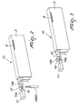
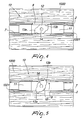
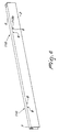
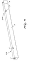
- a draft excluder generally designated by the reference numeral 1, has a fixed profile 2, which has a substantially U-shaped transverse cross-section and is accommodated within a recess 1001 which is provided at a lower edge of a door 1000, and a movable profile 3, which is provided with a sealing means 4 and is at least partially inserted within the fixed profile 2.
- the movable profile 3 is functionally connected to the fixed profile 2 by means of an automatic movement means 5 which, during the closure of the door 1000, allows the movable profile 3 to pass from a raised position, in which the movable profile 3 and the sealing means 4 are spaced from the floor, to a lowered position, in which the movable profile 3 and the sealing means 4 are in contact with the floor.
- the recess 1001 in which the fixed profile 2 is accommodated, is obtained by means of a milling performed beforehand on the lower edge of the door 1000, with a transverse cross-section which is substantially complementary to the transverse cross-section of the fixed profile 2.
- the draft excluder 1 includes an expansion-type coupling means 10 arranged at its end and slidingly associated with a sliding guide 7, which is formed at a back 6 of the fixed profile 2 and is provided with a plurality of openings 8 formed on opposite sides of the sliding guide 7 so as to face each other.
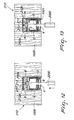
- the expansion-type coupling means 10 is constituted by a pair of substantially mutually identical devices, which are capable of passing from a closed condition, in which they do not protrude from the contour of the fixed profile 2, to an open position, in which they protrude at least partially laterally from the fixed profile 2, interfering with the recess 1001 and consequently fixing the draft excluder 1 to the door 1000.
- each of the devices that constitute the expansion-type coupling means 10 is formed by a base support 11, with a transverse cross-section which is substantially complementary to the transverse cross-section of the sliding guide 7, and by an engagement member, which in practice is constituted by a pawl 12 which is rotatably joined to the base support 11.
- the pawl 12 is provided with a shaped portion 14, or with a notch.
- the shaped portion 14 allows to impart thereto a rotation by using a suitable tool 2000, constituted by a simple hex key.
- transition in fact occurs from the closed condition, in which the protrusions 13a and 13b do not protrude from the contour of the fixed profile 2, to the open condition, in which the protrusions 13a and 13b protrude at least partially from the fixed profile 2 through the openings 8 and interfere with the recess 1001, fixing the draft excluder 1 to the door 1000.
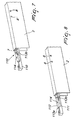
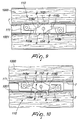
- each of the devices that constitute the expansion-type coupling means is composed of a base support 111, which has a transverse cross-section which is substantially complementary to the transverse cross-section of the sliding guide 7, and an engagement member, which is constituted by an eccentric member 112 which is rotatably joined to the base support 111, is provided with two diametrically opposite cams 115a and 115b, and is functionally connected to a pair of hooks 113a and 113b, which in turn are articulated with respect to the base support 111 I substantially at the two ends thereof.
- a shaped portion or notch 114 is provided on the eccentric member 112 and, through the open side of the fixed profile 2, allows to impart thereto a rotation by using a suitable tool 2000, which is constituted by a simple hex key.
- transition is in fact achieved from the closed condition, in which the hooks 113a and 113b do not protrude from the contour of the fixed profile 2, to the open condition, in which the hooks 113a and 113b, pushed by the cams 115a and 115b of the eccentric member 112, protrude from the fixed profile 2 through the openings 8 and interfere with the recess 1001, fixing the draft excluder 1 to the door 1000.
- the hooks 113a and 113b can be simply in contact with the eccentric member 112 or, preferably, can be articulated to the eccentric member 112 at the two cams 115a and 115b.
- each of the devices that constitute the expansion-type coupling means comprises a base support 211, which has a transverse cross-section which is substantially complementary to the transverse cross-section of the sliding guide 7, and an engagement member constituted by a pair of mutually facing sliders 212a and 212b, which are transversely and slidingly associated with the base support 211, and between which a wedge 213 is interposed.
- the operation of the draft excluder according to the invention is evident from what has been described and illustrated, and in particular it is evident that it is sufficient to arrange the expansion-type coupling means, designated respectively by the reference numerals 10, 110 and 210, inside the sliding guide 7 at the openings 8 and then, by means of a tool 2000, constituted by a hex key or a screwdriver, impart respectively a rotation substantially of a quarter turn to the pawl 12, a rotation of substantially one eighth of a turn to the eccentric 112, or a translational motion in a direction which lies transversely to the sliding direction of the sliders 212a and 212b to the wedge 213, so as to cause the at least partial protrusion from the fixed profile 2 of the engagement members that will interfere with the recess 1001 and consequently fix the draft excluder 1 to the door 1000.
- a tool 2000 constituted by a hex key or a screwdriver
- the tool 2000 used to make the engagement members pass from the closed condition to the open condition in practice is inserted in through holes 9, which are formed both on the sealing means 4 and on the movable profile 3 and allow to anchor to the door 1000 the draft excluder 1 even when the excluder is already completely assembled.
Landscapes
- Engineering & Computer Science (AREA)
- Civil Engineering (AREA)
- Structural Engineering (AREA)
- Specific Sealing Or Ventilating Devices For Doors And Windows (AREA)
- Wing Frames And Configurations (AREA)
- Chemical And Physical Treatments For Wood And The Like (AREA)
Applications Claiming Priority (1)
| Application Number | Priority Date | Filing Date | Title |
|---|---|---|---|
| ITVI20070058 ITVI20070058A1 (it) | 2007-02-28 | 2007-02-28 | Dispositivo paraspifferi, particolarmente per porte in legno. |
Publications (2)
| Publication Number | Publication Date |
|---|---|
| EP1965016A2 true EP1965016A2 (de) | 2008-09-03 |
| EP1965016A3 EP1965016A3 (de) | 2013-03-06 |
Family
ID=39477978
Family Applications (1)
| Application Number | Title | Priority Date | Filing Date |
|---|---|---|---|
| EP08002735A Withdrawn EP1965016A3 (de) | 2007-02-28 | 2008-02-14 | Dichtungsstreifen, insbesondere für Holztüren |
Country Status (2)
| Country | Link |
|---|---|
| EP (1) | EP1965016A3 (de) |
| IT (1) | ITVI20070058A1 (de) |
Cited By (2)
| Publication number | Priority date | Publication date | Assignee | Title |
|---|---|---|---|---|
| EP2840221A1 (de) * | 2011-08-02 | 2015-02-25 | Planet GDZ AG | Dichtung für eine schwellenlose Türe |
| IT201700010384A1 (it) * | 2017-01-31 | 2018-07-31 | Luca Geron | Dispositivo paraspifferi ad ancoraggio facilitato |
Family Cites Families (3)
| Publication number | Priority date | Publication date | Assignee | Title |
|---|---|---|---|---|
| IT1296362B1 (it) * | 1997-11-05 | 1999-06-25 | Luigi Geron | Dispositivo paraspifferi autoregolante |
| IT1315306B1 (it) * | 2000-03-31 | 2003-02-10 | Luigi Geron | Dispositivo di fissaggio per apparecchi paraspifferi automatici edapparecchio paraspifferi incorporante tale dispositivo |
| ITVI20050122A1 (it) * | 2005-04-26 | 2006-10-27 | Luigi Geron | Dispositivo antispiffero particolarmente per infissi |
-
2007
- 2007-02-28 IT ITVI20070058 patent/ITVI20070058A1/it unknown
-
2008
- 2008-02-14 EP EP08002735A patent/EP1965016A3/de not_active Withdrawn
Cited By (2)
| Publication number | Priority date | Publication date | Assignee | Title |
|---|---|---|---|---|
| EP2840221A1 (de) * | 2011-08-02 | 2015-02-25 | Planet GDZ AG | Dichtung für eine schwellenlose Türe |
| IT201700010384A1 (it) * | 2017-01-31 | 2018-07-31 | Luca Geron | Dispositivo paraspifferi ad ancoraggio facilitato |
Also Published As
| Publication number | Publication date |
|---|---|
| EP1965016A3 (de) | 2013-03-06 |
| ITVI20070058A1 (it) | 2008-09-01 |
Similar Documents
| Publication | Publication Date | Title |
|---|---|---|
| CA2364823C (en) | Casement window with improved tie bar guide and striker | |
| CA2345207A1 (en) | Snap-on door sweep | |
| EA000888B1 (ru) | Поддерживающее средство для экранирующего устройства | |
| KR101910365B1 (ko) | 적어도 리프팅 되며, 바람직하게는 이동 가능한 윈도우 또는 도어의 윙을 위한 피팅장치. | |
| EP2447452A1 (de) | Schließblech für ein Schloss, Anordnung aus Schließblech und Schloss und/oder eines Schließelements und Verfahren zum Schließen eines Schließelements | |
| FI3101214T4 (fi) | Tiivisteet, ovilevyt ja menetelmä tiivisteiden ja ovien asentamiseksi tiivisteiden kera | |
| PL198221B1 (pl) | Okucie blokujące | |
| GB2105428A (en) | Improvements in or relating to a corner guide for drive rod fittings on windows, doors or the like | |
| CA2628755C (en) | Fire plate for a bored in lock assembly | |
| EP1145667A1 (de) | Verbesserter Haltewinkel für die Tür eines eingebauten Kühlschrankes | |
| KR20150112986A (ko) | 가이드 레일을 통해 가이드 방향으로 가구 부품을 가이드하기 위한 주행부 및 가구 피팅 | |
| CN208943395U (zh) | 固定钩环 | |
| CN1158510C (zh) | 冷却或冷冻装置的门的密封件 | |
| PL199797B1 (pl) | Zespół okucia ramy skrzydła okna lub drzwi | |
| EP1167667B1 (de) | Beschlagelement für ein Fenster oder eine Tür und Verfahren zur Montage | |
| KR100866997B1 (ko) | 건물용 현관문 | |
| CN116458755A (zh) | 用于窗户配件的连接轨道 | |
| EP1972723A2 (de) | Revisionsabdeckung | |
| GB2391257A (en) | Bi-fold door assembly | |
| GB2546332A (en) | Locking cluster and drive line connector | |
| KR100991053B1 (ko) | 미닫이문의 도난방지용 잠금장치 | |
| EP2233678B1 (de) | Befestigungsverbindungsglied für jalousien | |
| JP2009062750A (ja) | 扉用ピボットヒンジ及びこれを備えた扉 | |
| EP2924208B1 (de) | Gegen gewaltsames eindringen beständiges schloss | |
| NL2038146B1 (en) | Frame-securing clip |
Legal Events
| Date | Code | Title | Description |
|---|---|---|---|
| PUAI | Public reference made under article 153(3) epc to a published international application that has entered the european phase |
Free format text: ORIGINAL CODE: 0009012 |
|
| AK | Designated contracting states |
Kind code of ref document: A2 Designated state(s): AT BE BG CH CY CZ DE DK EE ES FI FR GB GR HR HU IE IS IT LI LT LU LV MC MT NL NO PL PT RO SE SI SK TR |
|
| AX | Request for extension of the european patent |
Extension state: AL BA MK RS |
|
| PUAL | Search report despatched |
Free format text: ORIGINAL CODE: 0009013 |
|
| AK | Designated contracting states |
Kind code of ref document: A3 Designated state(s): AT BE BG CH CY CZ DE DK EE ES FI FR GB GR HR HU IE IS IT LI LT LU LV MC MT NL NO PL PT RO SE SI SK TR |
|
| AX | Request for extension of the european patent |
Extension state: AL BA MK RS |
|
| RIC1 | Information provided on ipc code assigned before grant |
Ipc: E06B 7/21 20060101AFI20130130BHEP |
|
| 17P | Request for examination filed |
Effective date: 20130808 |
|
| RBV | Designated contracting states (corrected) |
Designated state(s): AT BE BG CH CY CZ DE DK EE ES FI FR GB GR HR HU IE IS IT LI LT LU LV MC MT NL NO PL PT RO SE SI SK TR |
|
| AKX | Designation fees paid |
Designated state(s): AT BE BG CH CY CZ DE DK EE ES FI FR GB GR HR HU IE IS IT LI LT LU LV MC MT NL NO PL PT RO SE SI SK TR |
|
| 17Q | First examination report despatched |
Effective date: 20131112 |
|
| GRAP | Despatch of communication of intention to grant a patent |
Free format text: ORIGINAL CODE: EPIDOSNIGR1 |
|
| INTG | Intention to grant announced |
Effective date: 20141106 |
|
| STAA | Information on the status of an ep patent application or granted ep patent |
Free format text: STATUS: THE APPLICATION IS DEEMED TO BE WITHDRAWN |
|
| 18D | Application deemed to be withdrawn |
Effective date: 20150317 |