EP1965178A2 - Capteur inductif - Google Patents
Capteur inductif Download PDFInfo
- Publication number
- EP1965178A2 EP1965178A2 EP08003471A EP08003471A EP1965178A2 EP 1965178 A2 EP1965178 A2 EP 1965178A2 EP 08003471 A EP08003471 A EP 08003471A EP 08003471 A EP08003471 A EP 08003471A EP 1965178 A2 EP1965178 A2 EP 1965178A2
- Authority
- EP
- European Patent Office
- Prior art keywords
- metal sheet
- sensor according
- inductive sensor
- insulating layer
- winding
- Prior art date
- Legal status (The legal status is an assumption and is not a legal conclusion. Google has not performed a legal analysis and makes no representation as to the accuracy of the status listed.)
- Granted
Links
Images



Classifications
-
- G—PHYSICS
- G01—MEASURING; TESTING
- G01D—MEASURING NOT SPECIALLY ADAPTED FOR A SPECIFIC VARIABLE; ARRANGEMENTS FOR MEASURING TWO OR MORE VARIABLES NOT COVERED IN A SINGLE OTHER SUBCLASS; TARIFF METERING APPARATUS; MEASURING OR TESTING NOT OTHERWISE PROVIDED FOR
- G01D5/00—Mechanical means for transferring the output of a sensing member; Means for converting the output of a sensing member to another variable where the form or nature of the sensing member does not constrain the means for converting; Transducers not specially adapted for a specific variable
- G01D5/12—Mechanical means for transferring the output of a sensing member; Means for converting the output of a sensing member to another variable where the form or nature of the sensing member does not constrain the means for converting; Transducers not specially adapted for a specific variable using electric or magnetic means
- G01D5/14—Mechanical means for transferring the output of a sensing member; Means for converting the output of a sensing member to another variable where the form or nature of the sensing member does not constrain the means for converting; Transducers not specially adapted for a specific variable using electric or magnetic means influencing the magnitude of a current or voltage
- G01D5/20—Mechanical means for transferring the output of a sensing member; Means for converting the output of a sensing member to another variable where the form or nature of the sensing member does not constrain the means for converting; Transducers not specially adapted for a specific variable using electric or magnetic means influencing the magnitude of a current or voltage by varying inductance, e.g. by a movable armature
- G01D5/2006—Mechanical means for transferring the output of a sensing member; Means for converting the output of a sensing member to another variable where the form or nature of the sensing member does not constrain the means for converting; Transducers not specially adapted for a specific variable using electric or magnetic means influencing the magnitude of a current or voltage by varying inductance, e.g. by a movable armature by influencing the self-induction of one or more coils
-
- F—MECHANICAL ENGINEERING; LIGHTING; HEATING; WEAPONS; BLASTING
- F16—ENGINEERING ELEMENTS AND UNITS; GENERAL MEASURES FOR PRODUCING AND MAINTAINING EFFECTIVE FUNCTIONING OF MACHINES OR INSTALLATIONS; THERMAL INSULATION IN GENERAL
- F16C—SHAFTS; FLEXIBLE SHAFTS; ELEMENTS OR CRANKSHAFT MECHANISMS; ROTARY BODIES OTHER THAN GEARING ELEMENTS; BEARINGS
- F16C29/00—Bearings for parts moving only linearly
-
- G—PHYSICS
- G01—MEASURING; TESTING
- G01B—MEASURING LENGTH, THICKNESS OR SIMILAR LINEAR DIMENSIONS; MEASURING ANGLES; MEASURING AREAS; MEASURING IRREGULARITIES OF SURFACES OR CONTOURS
- G01B7/00—Measuring arrangements characterised by the use of electric or magnetic techniques
- G01B7/02—Measuring arrangements characterised by the use of electric or magnetic techniques for measuring length, width or thickness
- G01B7/023—Measuring arrangements characterised by the use of electric or magnetic techniques for measuring length, width or thickness for measuring distance between sensor and object
-
- G—PHYSICS
- G01—MEASURING; TESTING
- G01B—MEASURING LENGTH, THICKNESS OR SIMILAR LINEAR DIMENSIONS; MEASURING ANGLES; MEASURING AREAS; MEASURING IRREGULARITIES OF SURFACES OR CONTOURS
- G01B7/00—Measuring arrangements characterised by the use of electric or magnetic techniques
- G01B7/14—Measuring arrangements characterised by the use of electric or magnetic techniques for measuring distance or clearance between spaced objects or spaced apertures
-
- Y—GENERAL TAGGING OF NEW TECHNOLOGICAL DEVELOPMENTS; GENERAL TAGGING OF CROSS-SECTIONAL TECHNOLOGIES SPANNING OVER SEVERAL SECTIONS OF THE IPC; TECHNICAL SUBJECTS COVERED BY FORMER USPC CROSS-REFERENCE ART COLLECTIONS [XRACs] AND DIGESTS
- Y10—TECHNICAL SUBJECTS COVERED BY FORMER USPC
- Y10T—TECHNICAL SUBJECTS COVERED BY FORMER US CLASSIFICATION
- Y10T29/00—Metal working
- Y10T29/49—Method of mechanical manufacture
- Y10T29/49002—Electrical device making
- Y10T29/4902—Electromagnet, transformer or inductor
Definitions
- the invention relates to an inductive sensor according to the preamble of claim 1, a position measuring system with this sensor and a method for its production.
- An inductive sensor is for example from the EP 0 743 508 A2 known.
- a sensor is shown in FIGS. 16A and 16B, in which a plurality of electrical line windings 102, 104 are applied to a substrate 126.
- the line windings are arranged in multiple layers, which are electrically separated from each other by thin insulating layers 162.
- an insulating layer 162 is also provided, so that the line windings are protected against environmental influences such as penetrating electrically conductive liquids.
- the substrate 126 is in the form of an electrical circuit board. This substrate gives the entire assembly the necessary mechanical strength.
- the lead winding is made from a thin copper layer applied over its entire area by a photochemical etching process.
- the insulating layers 162 are lacquer layers. The thickness of the line windings and the insulating layers is greatly exaggerated in FIG. 16B compared to the substrate.
- the signals generated by the sensor when scanning the assigned material measure are weakened. This weakening will u. a. caused by eddy currents induced by the AC currents in the sensor line turns. These eddy currents can be minimized by using a particularly thin cover plate (thickness 50 to 200 ⁇ m).
- the signal is weakened by the increased distance between the line windings and the material measure.
- This distance is on the one hand increased by the thickness of the cover plate.
- the distance is increased by the adhesive layer between the sensor and the cover plate.
- the distance is further increased by the covering insulating layer which is provided in the preparation of the line winding on the substrate.
- the pitch is 1 mm in the above-mentioned linear position measuring device, with smaller pitches being sought to increase the measurement accuracy. As far as technically possible, the said distance should be as small as possible.
- the metal sheet is used to cover simultaneously as a substrate that gives the line winding the necessary stability.
- the separate substrate can therefore be dispensed with.
- On a separate adhesive layer can be omitted.
- an insulating layer must be provided on the side of the line winding. This can be done much thinner than a separate adhesive layer.
- the insulating layer is preferably thinner than 10 ⁇ m. Most preferably, a single-phase layer is provided, since these can be made very thin.
- the metal sheet is preferably thinner than 0.2 mm.
- the line winding can be produced in a simple manner with a known photochemical etching process, it is designed as a planar spiral.
- a full-area metal layer preferably of copper, is first applied to the substrate and coated with a photosensitive lacquer.
- the desired conductor structures are then exposed by means of a mask on this lacquer.
- the exposed lacquer surfaces are then removed chemically.
- the exposed areas of the metal layer can thus be etched away with an etching liquid, so that only the desired line windings remain.
- junction-free planar conductor arrangements can be produced inexpensively, which is why the aforementioned spiral-shaped coils are preferred.
- the spiral need not necessarily be circular for this purpose. It may also be provided square or rectangular shapes. In order for the sensor to emit a sufficiently strong signal, the spiral has at least 10 turns.
- the insulating layer can be made very thin by using a spin method.
- a liquid plastic preferably polyimide
- applied to the metal sheet which is then placed around an axis perpendicular to the sheet plane in rapid rotation, so that the liquid plastic is distributed by the centrifugal force to a thin layer over the entire surface of the sheet. Excess plastic is thrown off the sheet surface. After the spinning process, the plastic is cured to a solid layer.
- Polyimide is particularly well suited for the production of very thin insulating layers. In addition, adheres to this material, the subsequently applied metal layer for the line windings particularly well.
- the sensors can be produced particularly cost-effectively if the insulating layer and the at least one line winding for a plurality of sensors are each applied simultaneously to a metal sheet, wherein then the individual sensors are preferably cut out of the metal sheet with a laser beam.
- the process steps in the photochemical etching and the application of the insulating layer can be carried out simultaneously with little additional effort for several sensors simultaneously, so that the workload per sensor decreases.
- the division of the sheet with a laser beam is preferred, because in this case no bending of the thin metal sheet is to be feared.
- the sensor may comprise a housing having at least a first opening, wherein the first opening is closed with the metal sheet such that the conduit winding is located in the interior of the housing.
- the housing supports the relatively unstable metal sheet.
- the metal sheet can be fastened via the housing to a superordinate subassembly such as, for example, the guide carriage of a linear roller bearing.
- the housing has for this purpose fastening means which are adapted to adjust the distance between the metal sheet and the material measure on the guide rail to the desired low value of preferably less than 0.1 mm.
- the metal sheet should not touch the material measure.
- the housing also serves to protect the sensitive line winding. Therefore, it makes sense if the metal sheet completely closes the first opening, so that no foreign matter such as coolant / lubricant can penetrate into the housing.
- the preferably flat metal sheet is welded to the housing, wherein the weld does not protrude beyond the plane defined by the outer surface of the metal sheet.
- the housing is preferably made of metal in this embodiment, as a result of a particularly strong welded joint can be produced.
- the welded joint can easily be made liquid-tight.
- a flat metal sheet is preferred because it is particularly easy to produce. The same applies to the flat contact surface for the metal sheet on the housing.
- the metal sheet may be welded to the housing by means of a laser beam.
- a laser beam By using a laser beam, it is particularly easy to produce a weld that does not protrude over the metal sheet. This is due to the fact that a very thin weld seam can be generated with a laser beam.
- the laser beam can be directed by means of a suitable optics very accurately to the desired spot weld. In the present case, it has proven useful to align the laser beam to a position on the edge of the housing, which is located about half the weld seam width away from the support surface of the metal sheet, so that the weld edge just barely detects the metal sheet. In this way, a projection of the weld can be effectively prevented.
- the housing may have at least one second opening, in which a potting compound is filled, which supports the metal sheet.
- a second housing opening the contacting of the cable winding is made with the connection cable for the transmitter.
- the second opening together with the first opening preferably forms an opening in the housing, so that the rear side of the metal sheet is particularly easily accessible.
- the potting compound serves on the one hand to protect the line winding and the contact of environmental influences.
- the potting compound should cover or enclose all components to be protected.
- the potting compound should give the metal sheet the necessary strength, so that it can not be bent by carelessness, for example when mounting the sensor.
- a flexible circuit board with a Mull istungens- and a connection portion may be provided, wherein the contacting portion is completely covered with the potting compound and wherein the connection portion protrudes from the potting compound.
- a flexible printed circuit board is a particularly cost-effective way to realize multiple electrical connection lines between two modules. In connection with the present sensor usually many connecting lines are necessary because it can have several separate Samswindungen that need to be connected to the transmitter. With several separate line windings, among other things, the evaluation accuracy of the relevant position measuring device can be increased.
- the contacting section of the flexible printed circuit board is preferably arranged parallel to the metal sheet, whereby the distance between the contacting points on the flexible printed circuit board and on the metal sheet can be made particularly small, in particular in the case that the contacting points are distributed over the entire surface of the metal sheet.
- the fact that the contacting portion is covered with potting compound, the contacting points are particularly well protected against environmental influences.
- a separating layer which has a substantially lower modulus of elasticity and at least five times the thickness of the metal sheet. With the separating layer of the contacting portion is aligned relative to the metal sheet.
- the separating layer is preferably made of an electrically non-conductive material and is preferably provided on both sides with an adhesive layer, so that there is a firm connection between the contact portion and metal sheet. In order to avoid that unevenness of the contacting section is transferred to the metal sheet, the separating layer has the said thickness or elastic modulus.
- At least one contact surface can be provided on the contacting section of the flexible printed circuit board, which is electrically conductively connected to the at least one line winding on the metal sheet via a wire, wherein an electrical conductor leads from the contact surface into the connection section of the flexible printed circuit board.
- the proposed bonding a particularly cost-effective connection between the Needlesssensabêt and the conduit winding is possible because conventional automated devices can be used for the production.
- the wires in question are preferably made very thin (less than 0.1 mm in diameter) and made of aluminum or gold. Due to the low strength of the wires is to ensure that the thermal expansion coefficients of the potting compound, the wires, the contacting and the metal sheet are coordinated so that the wires do not tear due to temperature changes.
- connection point between the wire and the at least one line winding is not covered by the contacting portion of the flexible circuit board, so that it is easily accessible to the bonding device.
- Fig. 1 and Fig. 2 is an inventive inductive sensor generally designated 10. It comprises a housing 40 with a slot-shaped opening 46, which at its ends a first and a second opening 41; 42 has.
- the housing is made of stainless and non-magnetic steel and is manufactured using the Metal Injection Molding (MIM) process.
- MIM Metal Injection Molding
- the first opening 41 of the housing is closed with a 100 micron thick metal sheet, which consists of stainless and non-magnetic steel.
- a 100 micron thick metal sheet which consists of stainless and non-magnetic steel.
- seven contact surfaces 24 are shown on the metal sheet, which are arranged in two rows. Between the contact surfaces 24, the (not shown) line windings are provided, which according to the embodiment of FIG. 9 in conjunction with FIG. 16 of EP 1 164 358 B1 are executed.
- the contact surfaces 24 are electrically connected to the line windings.
- a flexible printed circuit board 60 having a contacting portion 61 and a connection portion 62, on which in turn seven contact surfaces 64 and 65 are provided, which are electrically conductively connected to each other.
- the width b of the connection section 62 is made smaller than the distance a of the contact surfaces 24, so that the connection section does not cover the contact surfaces 24.
- the contact surfaces 24 on the metal sheet and the contact surfaces 65 on the connection section are electrically conductively connected to one another via thin aluminum wires, so that an overall electrically conductive connection exists between the contact surfaces 64 on the contacting section and the line windings.
- a release layer 63 of double-sided adhesive tape is attached to said components.
- a sealing compound is filled up to the level 45 in order to protect the above-mentioned components from environmental influences, in particular penetrating liquids.
- the potting compound gives the metal sheet the necessary stability.
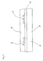
- Fig. 3 is a rough schematic cross section of the metal sheet 21 with the line windings 22, the electrically insulating layer 23 and an electrically insulating protective layer 26 is shown.
- the insulating layers 23; 26 are each formed by a single, single-phase polyimide layer.
- the cable turns are made of copper and are about 2 microns thick.
- the width of the line windings and their distance is about 10 microns. The values mentioned should be as small as possible so that as many line windings as possible can be accommodated on the given area, so that the sensor is very sensitive.
- Fig. 3 For the sake of clarity, only one layer is shown with conductor tracks. Of course, u are for line intersections. ⁇ . Provided in a known manner further layers with copper lines, which are separated from each other by polyimide layers electrically.
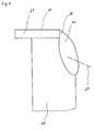
- Fig. 4 shows a cross section of the weld 44, with which the metal sheet 21 is fixed to the housing 40.
- the laser weld was applied so that it does not protrude beyond the outer surface 25 of the metal sheet.
- a laser beam was used in the Fig. 4 directed alignment directed to the housing so that it melts.
- the laser power has just been set so high that the molten metal of the housing just barely detects the metal sheet. Due to the surface tension of the melt, the end face 28 of the metal sheet is completely wetted without the finished weld over the outer surface 25 of the metal sheet.
- Fig. 5 It is shown how the sensor 10 according to the invention cooperates with a linear measuring graduation 81.
- the measuring graduation 81 is designed in the form of a sheet metal strip made of magnetizable steel sheet, which has a plurality of periodically arranged rectangular cutouts. It is according to the EP 1 052 480 B1 attached to the guide rail 80 of a linear roller bearing.
- the sensor 10 is in the measuring head of DE 103 47 360 A1 housed, which in turn is attached to the carriage of the linear roller bearing.
Landscapes
- Physics & Mathematics (AREA)
- General Physics & Mathematics (AREA)
- Engineering & Computer Science (AREA)
- General Engineering & Computer Science (AREA)
- Mechanical Engineering (AREA)
- Transmission And Conversion Of Sensor Element Output (AREA)
- Measurement Of Length, Angles, Or The Like Using Electric Or Magnetic Means (AREA)
Applications Claiming Priority (1)
| Application Number | Priority Date | Filing Date | Title |
|---|---|---|---|
| DE102007009994A DE102007009994A1 (de) | 2007-03-01 | 2007-03-01 | Induktiver Sensor |
Publications (3)
| Publication Number | Publication Date |
|---|---|
| EP1965178A2 true EP1965178A2 (fr) | 2008-09-03 |
| EP1965178A3 EP1965178A3 (fr) | 2013-10-02 |
| EP1965178B1 EP1965178B1 (fr) | 2015-04-08 |
Family
ID=39582238
Family Applications (1)
| Application Number | Title | Priority Date | Filing Date |
|---|---|---|---|
| EP08003471.3A Active EP1965178B1 (fr) | 2007-03-01 | 2008-02-26 | Capteur inductif |
Country Status (3)
| Country | Link |
|---|---|
| US (1) | US9605980B2 (fr) |
| EP (1) | EP1965178B1 (fr) |
| DE (1) | DE102007009994A1 (fr) |
Cited By (1)
| Publication number | Priority date | Publication date | Assignee | Title |
|---|---|---|---|---|
| DE102009048913A1 (de) * | 2009-10-10 | 2011-04-14 | Mtu Aero Engines Gmbh | Aufnahmevorrichtung für ein zu bearbeitendes Gasturbinenbauteil und Verfahren zum Bearbeiten desselben |
Families Citing this family (10)
| Publication number | Priority date | Publication date | Assignee | Title |
|---|---|---|---|---|
| DE102008022312B4 (de) | 2008-05-06 | 2022-12-01 | Robert Bosch Gmbh | Abtastvorrichtung mit U-förmigem Deckel und Linearlager |
| DE102009009308A1 (de) | 2009-02-17 | 2010-08-19 | Robert Bosch Gmbh | Linearbewegungsvorrichtung mit Abtastvorrichtung |
| DE102009042940A1 (de) | 2009-09-24 | 2011-05-19 | Robert Bosch Gmbh | Positionsmesseinrichtung mit sich mehrfach kreuzender Senderwindungsanordnung |
| DE102010045008B4 (de) * | 2010-09-10 | 2013-02-28 | Brose Fahrzeugteile Gmbh & Co. Kommanditgesellschaft, Hallstadt | Kapazitiver Abstandssensor |
| CH703722B1 (de) | 2010-09-14 | 2014-08-15 | Bosch Gmbh Robert | Kollektion von Linearlagern mit im Wesentlichen identischer Abtastbaugruppe. |
| DE102010042832B4 (de) * | 2010-10-22 | 2016-11-10 | Endress+Hauser Conducta Gmbh+Co. Kg | Verfahren zur Herstellung eines induktiven Sensors |
| EP3183817B1 (fr) * | 2014-08-22 | 2021-05-05 | Balluff GmbH | Capteur de proximité à induction présentant un mode de construction intégré |
| EP3355032B1 (fr) * | 2017-01-30 | 2019-03-27 | Dr. Johannes Heidenhain GmbH | Capteur de mesure de position |
| DE102019214643A1 (de) | 2019-09-25 | 2021-03-25 | Robert Bosch Gmbh | Verfahren zur Herstellung eines Messkopfgehäuses, Deckel und Messkopfgehäuse |
| DE102020214020A1 (de) | 2020-11-09 | 2022-05-12 | Robert Bosch Gesellschaft mit beschränkter Haftung | Positionssensor und Führungswagen mit einem Positionssensor und Verfahren zur Herstellung eines Positionssensors |
Citations (5)
| Publication number | Priority date | Publication date | Assignee | Title |
|---|---|---|---|---|
| EP0743508A2 (fr) | 1995-05-16 | 1996-11-20 | Mitutoyo Corporation | Capteur de position employant un courant d'induction |
| EP1052480B1 (fr) | 1999-05-14 | 2004-03-03 | Rexroth Star GmbH | Dispositif de détection de la position relative de deux corps |
| DE10347360A1 (de) | 2003-10-11 | 2005-05-12 | Rexroth Star Gmbh | Führung mit Messeinrichtung und Verfahren zur Herstellung einer solchen Führung |
| DE10360941A1 (de) | 2003-12-23 | 2005-07-28 | Sensor-Technik Wiedemann Gmbh | Rohrförmiger Drucksensor |
| EP1164358B1 (fr) | 2000-06-16 | 2005-08-24 | AMO Automatisierung Messtechnik Optik GmbH | Système inductif de mesure de longueur |
Family Cites Families (21)
| Publication number | Priority date | Publication date | Assignee | Title |
|---|---|---|---|---|
| IE55855B1 (en) * | 1984-10-19 | 1991-01-30 | Kollmorgen Ireland Ltd | Position and speed sensors |
| JPH0789119B2 (ja) * | 1986-05-30 | 1995-09-27 | 住友電気工業株式会社 | 電磁発電式回転センサ |
| FR2650471B1 (fr) * | 1989-07-27 | 1991-10-11 | Bull Sa | Procede de formation de piliers du reseau multicouche d'une carte de connexion d'au moins un circuit integre de haute densite |
| JP2539053B2 (ja) * | 1989-09-25 | 1996-10-02 | 三菱電機株式会社 | 回転電機の製造方法 |
| DE4205957A1 (de) * | 1992-02-27 | 1993-09-02 | Vogt Electronic Ag | Spulenaufbau |
| RU2040788C1 (ru) * | 1993-04-29 | 1995-07-25 | Товарищество с ограниченной ответственностью "Интрон Плюс" | Вихретоковый датчик для неразрушающего контроля металлизации отверстий и трубок и способ его изготовления |
| GB9605278D0 (en) * | 1996-03-13 | 1996-05-15 | Renishaw Plc | Opto-electronic scale reading apparatus |
| US5835350A (en) * | 1996-12-23 | 1998-11-10 | Lucent Technologies Inc. | Encapsulated, board-mountable power supply and method of manufacture therefor |
| US5901458A (en) * | 1997-11-21 | 1999-05-11 | Mitutoyo Corporation | Electronic caliper using a reduced offset induced current position transducer |
| DE19844738C1 (de) * | 1998-09-29 | 2000-05-31 | Siemens Ag | Dreidimensionaler, integrierter Spulenaufbau und Verfahren zur Herstellung des Spulenaufbaus |
| JP3504904B2 (ja) * | 2000-03-13 | 2004-03-08 | 株式会社ミツトヨ | 誘導型トランスデューサ及び電子ノギス |
| JP2002031545A (ja) * | 2000-07-13 | 2002-01-31 | Mitsutoyo Corp | 相対変位検出ユニット |
| DE10066293B4 (de) * | 2000-09-29 | 2007-11-29 | Balluff Gmbh | Induktiver Sensor |
| FR2820476B1 (fr) * | 2001-02-02 | 2004-04-02 | Skf Ab | Dispositif de detection de la vitesse de rotation d'un element tournant |
| US20020168800A1 (en) * | 2001-05-01 | 2002-11-14 | Smith Marshall E. | Method for forming a sensing apparatus having a cut-plane sensor and signal conditioner formed in a seamless monolithic substrate |
| GB2397652B (en) * | 2002-11-15 | 2005-12-21 | Immobilienges Helmut Fischer | Measurement probe for measurement of the thickness of thin layers |
| US6975108B2 (en) * | 2003-11-13 | 2005-12-13 | Yuli Bilik | Methods and devices for eddy current PCB inspection |
| JP2005150329A (ja) * | 2003-11-14 | 2005-06-09 | Canon Inc | 配線構造及びその作製方法 |
| WO2005090806A1 (fr) * | 2004-03-17 | 2005-09-29 | Siemens Aktiengesellschaft | Corps de guidage pour guidage lineaire aerostatique, et systeme de guidage lineaire aerostatique avec ledit corps de guidage |
| PT1580889E (pt) * | 2004-03-26 | 2008-03-17 | Senstronic S A | Sensor de proximidade indutivo |
| WO2006084675A1 (fr) * | 2005-02-08 | 2006-08-17 | Firma Pepperl + Fuchs Gmbh | Declencheur de proximite inductif base sur le principe du coefficient de couplage de transformateur |
-
2007
- 2007-03-01 DE DE102007009994A patent/DE102007009994A1/de not_active Withdrawn
-
2008
- 2008-02-26 EP EP08003471.3A patent/EP1965178B1/fr active Active
- 2008-02-26 US US12/037,554 patent/US9605980B2/en not_active Expired - Fee Related
Patent Citations (5)
| Publication number | Priority date | Publication date | Assignee | Title |
|---|---|---|---|---|
| EP0743508A2 (fr) | 1995-05-16 | 1996-11-20 | Mitutoyo Corporation | Capteur de position employant un courant d'induction |
| EP1052480B1 (fr) | 1999-05-14 | 2004-03-03 | Rexroth Star GmbH | Dispositif de détection de la position relative de deux corps |
| EP1164358B1 (fr) | 2000-06-16 | 2005-08-24 | AMO Automatisierung Messtechnik Optik GmbH | Système inductif de mesure de longueur |
| DE10347360A1 (de) | 2003-10-11 | 2005-05-12 | Rexroth Star Gmbh | Führung mit Messeinrichtung und Verfahren zur Herstellung einer solchen Führung |
| DE10360941A1 (de) | 2003-12-23 | 2005-07-28 | Sensor-Technik Wiedemann Gmbh | Rohrförmiger Drucksensor |
Cited By (1)
| Publication number | Priority date | Publication date | Assignee | Title |
|---|---|---|---|---|
| DE102009048913A1 (de) * | 2009-10-10 | 2011-04-14 | Mtu Aero Engines Gmbh | Aufnahmevorrichtung für ein zu bearbeitendes Gasturbinenbauteil und Verfahren zum Bearbeiten desselben |
Also Published As
| Publication number | Publication date |
|---|---|
| DE102007009994A1 (de) | 2008-09-04 |
| US9605980B2 (en) | 2017-03-28 |
| US20080211489A1 (en) | 2008-09-04 |
| EP1965178B1 (fr) | 2015-04-08 |
| EP1965178A3 (fr) | 2013-10-02 |
Similar Documents
| Publication | Publication Date | Title |
|---|---|---|
| EP1965178B1 (fr) | Capteur inductif | |
| EP3355032B1 (fr) | Capteur de mesure de position | |
| DE69832249T2 (de) | Chip-induktivität und sein herstellungsverfahren | |
| DE102019125537B3 (de) | Sensorvorrichtungen mit Sensorchip und Stromschiene | |
| EP0667514A2 (fr) | Méthode de fabrication de jauges de contrainte | |
| DE102015010349B4 (de) | Kodierermassstab und verfahren für seine herstellung | |
| DE69429293T2 (de) | Autoglasscheibe mit einer gedruckten Leiterstruktur | |
| DE102013201926A1 (de) | Verfahren zum elektrischen Kontaktieren eines Bauteils und Bauteilverbund | |
| DE10018269B4 (de) | Abtasteinheit | |
| EP0460249B1 (fr) | Jauge de contrainte | |
| EP3399284B1 (fr) | Capteur de mesure de position | |
| DE102016216330A1 (de) | Flexible Spulenordnung für einen magnetoelektrischen Weggeber, Weggeber und Herstellungsverfahren | |
| DE19843471A1 (de) | Druckerkennungsvorrichtung | |
| DE102021200441A1 (de) | Abtasteinheit und damit ausgestatteter drehgeber | |
| EP0992778A2 (fr) | Capteur et son procédé de fabricage | |
| DE68914214T2 (de) | Zusammenbau- und Packungsverfahren eines Sensorelementes. | |
| EP3263471B1 (fr) | Capteur d'étiquettes destiné à détecter des étiquettes sur une bande support | |
| EP4677368A1 (fr) | Transducteur doté d'un capteur de tension flexible | |
| DE3818191C2 (fr) | ||
| EP3708978B1 (fr) | Système compacte de mesure directe | |
| DE19927108A1 (de) | Verfahren zur Herstellung von Sensoren sowie Sensor, insbesondere Temperatursensor | |
| WO2019057582A1 (fr) | Condensateur à plaques équipé d'une plaque en matériau élastique | |
| EP0651912A1 (fr) | Boitier miniaturise pour composants electroniques | |
| DE102019214149A1 (de) | Steuergerät für ein Kraftfahrzeug und Verfahren zur Herstellung und Messung der Dichtigkeit eines Steuergeräts | |
| EP0453023B1 (fr) | Plaque de circuit flexible et procédé pour établir le contact d'au moins une surface de contact avec la plaque de circuit |
Legal Events
| Date | Code | Title | Description |
|---|---|---|---|
| PUAI | Public reference made under article 153(3) epc to a published international application that has entered the european phase |
Free format text: ORIGINAL CODE: 0009012 |
|
| AK | Designated contracting states |
Kind code of ref document: A2 Designated state(s): AT BE BG CH CY CZ DE DK EE ES FI FR GB GR HR HU IE IS IT LI LT LU LV MC MT NL NO PL PT RO SE SI SK TR |
|
| AX | Request for extension of the european patent |
Extension state: AL BA MK RS |
|
| RIN1 | Information on inventor provided before grant (corrected) |
Inventor name: HAUSER, KARIN Inventor name: HOLLWECK, ROMAN Inventor name: REUSING, GUENTE Inventor name: HOHNKE, FLORIAN Inventor name: STIER, ANTON |
|
| PUAL | Search report despatched |
Free format text: ORIGINAL CODE: 0009013 |
|
| AK | Designated contracting states |
Kind code of ref document: A3 Designated state(s): AT BE BG CH CY CZ DE DK EE ES FI FR GB GR HR HU IE IS IT LI LT LU LV MC MT NL NO PL PT RO SE SI SK TR |
|
| AX | Request for extension of the european patent |
Extension state: AL BA MK RS |
|
| RIC1 | Information provided on ipc code assigned before grant |
Ipc: H01L 21/48 20060101ALI20130823BHEP Ipc: H01L 23/14 20060101ALI20130823BHEP Ipc: G12B 9/06 20060101ALI20130823BHEP Ipc: G01D 5/20 20060101AFI20130823BHEP Ipc: F16C 29/00 20060101ALI20130823BHEP |
|
| 17P | Request for examination filed |
Effective date: 20140402 |
|
| 17Q | First examination report despatched |
Effective date: 20140502 |
|
| AKX | Designation fees paid |
Designated state(s): CH DE FR IT LI |
|
| REG | Reference to a national code |
Ref country code: DE Ref legal event code: R079 Ref document number: 502008012847 Country of ref document: DE Free format text: PREVIOUS MAIN CLASS: G01D0005200000 Ipc: F16C0029000000 |
|
| RIC1 | Information provided on ipc code assigned before grant |
Ipc: G01D 5/20 20060101ALI20140822BHEP Ipc: F16C 29/00 20060101AFI20140822BHEP |
|
| GRAP | Despatch of communication of intention to grant a patent |
Free format text: ORIGINAL CODE: EPIDOSNIGR1 |
|
| INTG | Intention to grant announced |
Effective date: 20141028 |
|
| GRAP | Despatch of communication of intention to grant a patent |
Free format text: ORIGINAL CODE: EPIDOSNIGR1 |
|
| GRAS | Grant fee paid |
Free format text: ORIGINAL CODE: EPIDOSNIGR3 |
|
| INTG | Intention to grant announced |
Effective date: 20150121 |
|
| RIN1 | Information on inventor provided before grant (corrected) |
Inventor name: HOLLWECK, ROMAN Inventor name: HAUSER, KARIN Inventor name: REUSING, GUENTER Inventor name: HOHNKE, FLORIAN Inventor name: STIER, ANTON |
|
| GRAA | (expected) grant |
Free format text: ORIGINAL CODE: 0009210 |
|
| AK | Designated contracting states |
Kind code of ref document: B1 Designated state(s): CH DE FR IT LI |
|
| REG | Reference to a national code |
Ref country code: CH Ref legal event code: EP |
|
| REG | Reference to a national code |
Ref country code: DE Ref legal event code: R096 Ref document number: 502008012847 Country of ref document: DE Effective date: 20150521 |
|
| REG | Reference to a national code |
Ref country code: DE Ref legal event code: R097 Ref document number: 502008012847 Country of ref document: DE |
|
| PLBE | No opposition filed within time limit |
Free format text: ORIGINAL CODE: 0009261 |
|
| STAA | Information on the status of an ep patent application or granted ep patent |
Free format text: STATUS: NO OPPOSITION FILED WITHIN TIME LIMIT |
|
| REG | Reference to a national code |
Ref country code: FR Ref legal event code: PLFP Year of fee payment: 9 |
|
| 26N | No opposition filed |
Effective date: 20160111 |
|
| REG | Reference to a national code |
Ref country code: FR Ref legal event code: PLFP Year of fee payment: 10 |
|
| REG | Reference to a national code |
Ref country code: FR Ref legal event code: PLFP Year of fee payment: 11 |
|
| PGFP | Annual fee paid to national office [announced via postgrant information from national office to epo] |
Ref country code: DE Payment date: 20250422 Year of fee payment: 18 |
|
| REG | Reference to a national code |
Ref country code: CH Ref legal event code: U11 Free format text: ST27 STATUS EVENT CODE: U-0-0-U10-U11 (AS PROVIDED BY THE NATIONAL OFFICE) Effective date: 20260301 |
|
| PGFP | Annual fee paid to national office [announced via postgrant information from national office to epo] |
Ref country code: IT Payment date: 20260227 Year of fee payment: 19 |
|
| PGFP | Annual fee paid to national office [announced via postgrant information from national office to epo] |
Ref country code: FR Payment date: 20260219 Year of fee payment: 19 |
|
| PGFP | Annual fee paid to national office [announced via postgrant information from national office to epo] |
Ref country code: CH Payment date: 20260301 Year of fee payment: 19 |