EP1965207B1 - Versiegelungszustandinspektionsvorrichtung und - verfahren - Google Patents
Versiegelungszustandinspektionsvorrichtung und - verfahren Download PDFInfo
- Publication number
- EP1965207B1 EP1965207B1 EP06834687A EP06834687A EP1965207B1 EP 1965207 B1 EP1965207 B1 EP 1965207B1 EP 06834687 A EP06834687 A EP 06834687A EP 06834687 A EP06834687 A EP 06834687A EP 1965207 B1 EP1965207 B1 EP 1965207B1
- Authority
- EP
- European Patent Office
- Prior art keywords
- hole
- layer
- conductive barrier
- barrier layer
- opening
- Prior art date
- Legal status (The legal status is an assumption and is not a legal conclusion. Google has not performed a legal analysis and makes no representation as to the accuracy of the status listed.)
- Not-in-force
Links
- 238000000034 method Methods 0.000 title claims description 13
- 238000007789 sealing Methods 0.000 title description 10
- 230000004888 barrier function Effects 0.000 claims description 84
- 239000000523 sample Substances 0.000 claims description 60
- 239000005022 packaging material Substances 0.000 claims description 53
- 238000007689 inspection Methods 0.000 claims description 42
- 230000002093 peripheral effect Effects 0.000 claims description 35
- 239000012815 thermoplastic material Substances 0.000 claims description 31
- 230000002950 deficient Effects 0.000 claims description 23
- 239000000758 substrate Substances 0.000 claims description 22
- 238000010030 laminating Methods 0.000 claims description 11
- 239000011800 void material Substances 0.000 claims description 11
- 230000000149 penetrating effect Effects 0.000 claims description 9
- 238000005520 cutting process Methods 0.000 claims description 8
- 229920001169 thermoplastic Polymers 0.000 claims description 8
- 239000004416 thermosoftening plastic Substances 0.000 claims description 8
- 238000004806 packaging method and process Methods 0.000 description 25
- 239000000047 product Substances 0.000 description 13
- 230000007547 defect Effects 0.000 description 11
- 238000004519 manufacturing process Methods 0.000 description 11
- 235000021056 liquid food Nutrition 0.000 description 6
- 230000007257 malfunction Effects 0.000 description 6
- 230000000694 effects Effects 0.000 description 5
- 239000004020 conductor Substances 0.000 description 3
- 238000001514 detection method Methods 0.000 description 3
- 235000011389 fruit/vegetable juice Nutrition 0.000 description 3
- 239000000463 material Substances 0.000 description 3
- 235000013336 milk Nutrition 0.000 description 3
- 239000008267 milk Substances 0.000 description 3
- 210000004080 milk Anatomy 0.000 description 3
- 239000010902 straw Substances 0.000 description 3
- 229910052782 aluminium Inorganic materials 0.000 description 2
- XAGFODPZIPBFFR-UHFFFAOYSA-N aluminium Chemical compound [Al] XAGFODPZIPBFFR-UHFFFAOYSA-N 0.000 description 2
- 239000012467 final product Substances 0.000 description 2
- 239000011888 foil Substances 0.000 description 2
- 239000002648 laminated material Substances 0.000 description 2
- 239000007788 liquid Substances 0.000 description 2
- 238000012986 modification Methods 0.000 description 2
- 230000004048 modification Effects 0.000 description 2
- 238000005452 bending Methods 0.000 description 1
- 238000007796 conventional method Methods 0.000 description 1
- 238000005336 cracking Methods 0.000 description 1
- 238000005516 engineering process Methods 0.000 description 1
- 235000013305 food Nutrition 0.000 description 1
- 239000003205 fragrance Substances 0.000 description 1
- 230000006872 improvement Effects 0.000 description 1
- 229910052500 inorganic mineral Inorganic materials 0.000 description 1
- 229910052751 metal Inorganic materials 0.000 description 1
- 239000002184 metal Substances 0.000 description 1
- 239000011707 mineral Substances 0.000 description 1
- 235000010755 mineral Nutrition 0.000 description 1
- 238000012545 processing Methods 0.000 description 1
- 238000012360 testing method Methods 0.000 description 1
- XLYOFNOQVPJJNP-UHFFFAOYSA-N water Substances O XLYOFNOQVPJJNP-UHFFFAOYSA-N 0.000 description 1
Images


Classifications
-
- G—PHYSICS
- G01—MEASURING; TESTING
- G01N—INVESTIGATING OR ANALYSING MATERIALS BY DETERMINING THEIR CHEMICAL OR PHYSICAL PROPERTIES
- G01N27/00—Investigating or analysing materials by the use of electric, electrochemical, or magnetic means
- G01N27/02—Investigating or analysing materials by the use of electric, electrochemical, or magnetic means by investigating impedance
- G01N27/04—Investigating or analysing materials by the use of electric, electrochemical, or magnetic means by investigating impedance by investigating resistance
- G01N27/20—Investigating the presence of flaws
-
- G—PHYSICS
- G01—MEASURING; TESTING
- G01M—TESTING STATIC OR DYNAMIC BALANCE OF MACHINES OR STRUCTURES; TESTING OF STRUCTURES OR APPARATUS, NOT OTHERWISE PROVIDED FOR
- G01M3/00—Investigating fluid-tightness of structures
- G01M3/02—Investigating fluid-tightness of structures by using fluid or vacuum
- G01M3/26—Investigating fluid-tightness of structures by using fluid or vacuum by measuring rate of loss or gain of fluid, e.g. by pressure-responsive devices, by flow detectors
- G01M3/32—Investigating fluid-tightness of structures by using fluid or vacuum by measuring rate of loss or gain of fluid, e.g. by pressure-responsive devices, by flow detectors for containers, e.g. radiators
- G01M3/3236—Investigating fluid-tightness of structures by using fluid or vacuum by measuring rate of loss or gain of fluid, e.g. by pressure-responsive devices, by flow detectors for containers, e.g. radiators by monitoring the interior space of the containers
- G01M3/3272—Investigating fluid-tightness of structures by using fluid or vacuum by measuring rate of loss or gain of fluid, e.g. by pressure-responsive devices, by flow detectors for containers, e.g. radiators by monitoring the interior space of the containers for verifying the internal pressure of closed containers
-
- G—PHYSICS
- G01—MEASURING; TESTING
- G01M—TESTING STATIC OR DYNAMIC BALANCE OF MACHINES OR STRUCTURES; TESTING OF STRUCTURES OR APPARATUS, NOT OTHERWISE PROVIDED FOR
- G01M3/00—Investigating fluid-tightness of structures
- G01M3/40—Investigating fluid-tightness of structures by using electric means, e.g. by observing electric discharges
-
- G—PHYSICS
- G01—MEASURING; TESTING
- G01N—INVESTIGATING OR ANALYSING MATERIALS BY DETERMINING THEIR CHEMICAL OR PHYSICAL PROPERTIES
- G01N33/00—Investigating or analysing materials by specific methods not covered by groups G01N1/00 - G01N31/00
- G01N33/0078—Testing material properties on manufactured objects
- G01N33/0081—Containers; Packages; Bottles
-
- B—PERFORMING OPERATIONS; TRANSPORTING
- B31—MAKING ARTICLES OF PAPER, CARDBOARD OR MATERIAL WORKED IN A MANNER ANALOGOUS TO PAPER; WORKING PAPER, CARDBOARD OR MATERIAL WORKED IN A MANNER ANALOGOUS TO PAPER
- B31B—MAKING CONTAINERS OF PAPER, CARDBOARD OR MATERIAL WORKED IN A MANNER ANALOGOUS TO PAPER
- B31B50/00—Making rigid or semi-rigid containers, e.g. boxes or cartons
- B31B50/006—Controlling; Regulating; Measuring; Improving safety
Definitions
- the present invention relates to an apparatus for and a method of inspecting a sealed condition of a paper-made packaging container with a liquid food product such as juice or milk contained filled therein as well as of a laminated material for packaging.
- a paper-made packaging container capable of preserving drinks or fluidized foods such as milk, juice, and mineral water at the room temperature is obtained, for instance, from an outermost layer made of a thermoplastic material, a paper-made substrate layer, a conductive barrier layer (made of, for instance, aluminum foil), and a heat-sealable innermost layer.
- a packaging container for a liquid food product has an opening for mounting thereon a lip from which the liquid food product is poured out or a cover, and a straw hole (opening) through which a straw is inserted, and the opening and the straw hole are provided at a vertex portion of the container. Furthermore a through hole as an opening is formed in the packaging container, and the opening is sealed with a barrier pull-tab from the outside and also with a batch film from the inside.
- FIG. 2 illustrates two examples of a packaging container. An opening 22 from which a liquid food product is poured out is formed at a vertex portion of a container 21 shown in FIG.
- a through hole 23 is formed in the laminated material for packaging, and an area including the through hole 23 is sealed by a paper-made substrate layer with an outermost layer made of a thermoplastic material, a conductive barrier layer, and a heat-sealable innermost layer laminated on both surfaces thereof.
- FIG. 3 illustrates an example of an apparatus used for manufacturing a packaging container shown in FIG. 2 .
- a packaging material web 31 having thermoplastic material layers on both outer and inner layers of the paper-made substrate layer and wound up into a form like a roll is fed out and transferred by a roller in the filling machine; a through hole is provided by an pull-tab applicator 33 in the packaging material; the area is sealed with a barrier pull-tab from the outer side and with a batch fill from the inner side; the packaging material web is sterilized in a sterilizer bath 32; the packaging material is formed into a tube-like form with a forming roller 34; both end sides of the packaging material are overlaid on each other to form an overlap; the overlapped area is sealed with a longitudinal seal element 36 along the longitudinal direction of the tubular section; a liquid food product is filled into the tube from a filling pipe 35; this tube is fed downward by a length corresponding to one packaging container and is sealed in the transversal direction with a trans
- a container produced for preserving a quality of a paper-made packaging container is required to be inspected for such properties as the appearance, the sealing capability, and the capability of maintaining the fragrance. Because there is not the paper-made substrate layer in the opening and an undesirable condition for sealing may occur, it is especially desirable to inspect the sealing capability of the opening. There have been proposed various ideas for improvement of the sealing capability.
- the ideas include, for instance, a seal inspection method enabling precise inspection of a sealed condition in a sealed section by energizing an aluminum foil layer inside a packaging material forming a paper-made container to measure an electrostatic capacitance (Refer to patent document 1), and a method in which flaps are peeled off from a wall of the container with the processing unit; a the container wall is cut with a sample preparing unit to prepare a sample; a sealing quality is inspected with a seal quality inspecting unit; a sealed zone is inspected with an image processor; and damages of the sealed zone are inspected with a seal damage inspecting unit (Refer to Patent document 2).
- Patent document 1 Japanese Patent Laid-Open Publication No. 2005-326276
- Patent document 2 Japanese Patent Laid-Open Publication No. 2004-144503
- Document EP 1 057 619 A1 discloses a control unit for checking the integrity of patch elements applied to respective openings of multilayer packaging material with at least one electrically conductive sheet, comprising at least one contact surface and detecting means connected to said packaging material and to the contact surface to determine the presence of microholes in the patch elements.
- An object of the present invention is to provide a sealed condition inspection apparatus and a sealed condition inspection method not requiring breaking up nor cutting of a paper-made container to prepare a sample for testing, and enabling inspection of all products on a production line.
- a sealed condition inspection apparatus that inspects an opening provided on a laminated packaging material having an thermoplastic outermost layer, a paper-made substrate layer, a conductive barrier layer, and a heat-sealable innermost layer, the opening prepared by partially cutting at least the thermoplastic outermost layer and the paper-made substrate layer and also the opening sealed in the easily-openable condition, and in the apparatus, a probe electrode and an earth electrode are provided outside and inside the opening, a current flowing between the probe electrode and the earth electrode is detected with the conductive barrier layer, and a sealed condition of the opening is inspected by a determining unit.
- an opening is formed with a through hole provided on a laminated packaging material and an area including an outer peripheral portion of the through hole is sealed with a barrier pull-tag from the outside and with a patch film from the inside;
- the probe electrode has a form covering up to the outer peripheral portion of the through hole and is provided on the patch film from the inside;
- the earth electrode is provided so that detection can be made for the conductive barrier layer on at least one edge face of the web-like laminated packaging material; and the determining unit detects conductivity between the probe electrode and the conductive barrier layer on the edge face of the through hole via the patch film to determine whether the sealed condition is defective or not.
- a sealed condition inspection apparatus an opening is formed with a through hole provided on a paper-made substrate layer, an area including the through hole is sealed by laminating an thermoplastic material outermost layer, a conductive barrier layer, and a heat-sealable innermost layer;
- the probe electrode has a form covering up to the outer peripheral portion of the through hole and is provided on the patch film from the inside;
- the earth electrode is provided so that detection can be made for the conductive barrier layer on at least one edge face of the web-like laminated packaging material; and the determining unit determines conductivity via the conductive barrier layer through a space penetrating the thermoplastic material outermost layer, the conductive barrier layer, and the heat-sealable innermost layer within the through hole to determine whether the sealed condition is defective or not.
- the present invention provides a sealed condition inspection method for inspecting an opening provided on a laminated packaging material having a thermoplastic outermost layer, a paper-made substrate layer, a conductive barrier layer, and a heat-sealable innermost layer, the opening prepared by partially cutting at least the thermoplastic outermost layer and the paper-made substrate layer and also the opening sealed in the easily-openable condition, wherein a probe electrode and an earth electrode are provided outside and inside the opening; a high voltage is loaded between the probe electrode and the earth electrode and a current flowing between the probe electrode and the earth electrode is detected via the conductive barrier layer; and a sealed condition of the opening is inspected by a determining unit.
- the opening is formed with a through hole provided on a laminated packaging material and an areas including an outer peripheral portion of the through hole is sealed with a barrier pull-tag from the outside and with a patch film from the inside;
- the probe electrode has a form covering up to an outer peripheral portion of the through hole and is provided on the patch film from the inner side;
- the earth electrode is provided so that the conductive barrier layer on at least one end face of the we-like laminated packaging material can be detected; and the determining unit detects conduction between the probe electrode and the conductive barrier layer on the end face of the through hole via the patch film to determine whether the sealed condition is defective or not.
- the opening is formed with a through hole provided on the paper-made substrate layer and an area including the through hole is sealed by laminating the thermoplastic material outermost layer, the conductive barrier layer, and the heat-sealable innermost layer;
- the probe electrode has a form covering at least an outer peripheral portion of the through hole and is provided on the heat-sealable innermost layer from the inner side;
- the earth electrode has a form covering up to an outer peripheral portion of the through hole and is provided on the thermoplastic material outermost layer from the outer side;
- the determining unit detects conduction by a void penetrating the thermoplastic material outermost layer, the conductive barrier layer, and the heat-sealable innermost layer inside the through hole to determine whether the sealed condition is defective or not.
- the opening provided at a vertex portion of a container is formed with a through hole provided on the paper-made substrate layer, and an area including the through hole is sealed by laminating the thermoplastic material outermost layer, the conductive barrier layer, and the heat-sealable innermost layer;
- the probe electrode has a form covering at least an outer peripheral portion of the through hole and is provided on the thermoplastic outermost layer from the outer side;
- the earth electrode is provided so that the conductive barrier layer can be detected provided at least one end face of the laminated packaging material formed on the container; and the determining unit detects conduction via the conduction barrier by a void penetrating the thermoplastic material outermost layer, the conductive barrier layer, and the heat-sealable innermost layer inside the through hole to determine whether the sealed condition is defective or not.
- the present invention provides the following advantages.
- the present invention provides an apparatus for inspecting an opening provided on a laminated packaging material having a thermoplastic material outermost layer, a paper-made material layer, a conductor barrier layer, and a heat-sealable innermost layer.
- This opening is formed by partially cutting at least the thermoplastic material outermost layer and the paper-made material layer and is sealed in the easily openable condition. Because the paper-made material layer is not present in the opening portion, the opening is mechanically weak and has a step or a peripheral portion, and therefore a sealing defect may occur, which in turn may give negative defects to the content.
- it is possible to detect a container having a sealing defect in the opening and also to prevent the container from being shipped as a product.
- the probe electrode and the earth electrode does not mechanically contact a surface of a laminated packaging material, and are provided in adjacent to each other in the outer side and in the inner side respectively, so that an outer surface of the laminated packaging material are not damaged by the electrodes (during inspection) and all products (packaging material and packaged containers) can be inspected on the production line).
- the conductor barrier layer which is one of layers in the laminated packaging material, and therefore parts, means and tools other than the electrodes are not required, which contributes to simplification of the apparatus.
- the use of the conductor barrier layer for inspection means that an electric current is flown between a probe electrode and an earth electrode by making use of conductivity of a barrier layer or by energizing the barrier layer when there is any defect, or that an electric current is flown between a probe electrode and an earth electrode by energizing through a pin hole, cracking, or a space inside the barrier layer when there is any defect.
- an opening is formed with a through hole provided on a laminated packaging material and an area including an outer peripheral portion of the through hole is sealed with a barrier pull-tag from the outside and with a patch film from the inside;
- the probe electrode has a form covering up to the outer peripheral portion of the through hole and is provided on the patch film from the inside;
- the earth electrode is provided so that detection can be made for the conductive barrier layer on at least one edge face of the web-like laminated packaging material; and the determining unit detects conductivity between the probe electrode and the conductive barrier layer on the edge face of the through hole via the patch film to determine whether the sealed condition is defective or not.
- Each layer of the laminated packaging material is exposed on an end face of a peripheral portion of the through hole, and therefore the barrier effect is not provided in the opening.
- the opening is sealed with a pull-tab providing the barrier effect from the outer side and also with a patch film from the inner side to cover the peripheral portion. If there is any pin hole in the peripheral portion of the inner patch film which is relatively weak mechanically , a content liquid may ooze out from the portion or atmospheric air may come into the inside, which may negatively affect the content.
- the probe electrode is provided on the patch film from the inner side, when there is any pin hole in the peripheral portion of the inner patch film, the probe electrode and the conductive barrier layer on an end face of the through holt are conducted to each other via the pin hole, and furthermore inside of the conductive barrier layer becomes conductive. Furthermore, because the earth electrode is provided so that the conductive barrier layer at least on an end face of the web-like laminated packaging material can be detected, when any defect is caused by the pin hole, a current flows between the probe electrode and the earth electrode via the conductive barrier layer.
- the probe electrode has a form covering up to an outer peripheral portion of the through hole, even if there is any pin hole (causing no defect) at a position off from the outer peripheral portion of the through hole inside the inner patch film or inside the heat-sealable innermost layer, an electric current does not flow between the probe electrode and the earth electrode, so that a malfunction detecting a not-defective condition as a defective condition can be prevented.
- an opening is formed with a through hole provided on a paper-made substrate layer, an area including the through hole is sealed by laminating an thermoplastic material outermost layer, a conductive barrier layer, and a heat-sealable innermost layer. Because of the configuration, the opening can be inspected before a packaging material is formed into a container and a content is filled in the container. This configuration be preferable because inspection of a sealed condition of the opening becomes more difficult after the packaging material is formed into a container and a content is filled in the container.
- a probe electrode having a form covering up to at least a peripheral portion of the through hole is provided on a heat-sealable innermost layer from the inner side. Even when there is any pin hole (causing no defect) at a position off from the outer peripheral portion of the through hole inside the inner patch film or inside the heat-sealable innermost layer, an electric current does not flow between the probe electrode and the earth electrode, so that a malfunction detecting a not-defective condition as a defective condition can be prevented. Furthermore, the earth electrode has a form covering up to the peripheral portion of the through hole, a malfunction enabling conductivity with the conductive barrier layer on an end face of the web-like laminated packaging material never occurs. In this embodiment, the determining unit detects conductivity through a void penetrating the thermoplastic material outermost layer, the conductive barrier layer, and the heat-sealable innermost layer to determine whether the sealed condition is defective or not.
- an opening at a vertex of a container is formed with a through hole provided on a paper-made substrate layer, and an area including the through hole is sealed by laminating a thermoplastic material outermost layer, a conductive barrier layer, and a heat-sealable innermost layer.
- inspection can be made after a packaging material is formed into a container and a content is filled in the container, namely after a final product is manufactured. Because of the configuration, a product with high reliability can be shipped.
- a probe electrode having a form covering up to at least a peripheral portion of the through hole is provided on the thermoplastic material outermost layer from the outer side.
- An earth electrode is provided so that the conductive barrier layer provided at least on an end face of the laminated packaging material formed into a container can be detected.
- the conductive barrier layer at an end face of the laminated packaging material is exposed when bent in various ways. Conductivity with the earth electrode is provided by making use of the exposed face.
- a void penetrating the thermoplastic material outermost layer, the conductive barrier iayer, and the heat-sealable innermost layer is generated.
- the conductive barrier layer is exposed on an end face of the void or the pin hole, and an electric current flows between the probe electrode and the earth electrode via the conductive face.
- the determining unit detect the conductivity to determine whether the sealed condition is defective or not.
- Fig. 1 provides a perspective view illustrating a packaging container and an unsealing apparatus for the packaging container according to a first embodiment of the present invention, and a partially enlarged view illustrating a function of a hinge section.
- Fig. 2 is a side view illustrating an appearance of an unsealing apparatus for a container according to a second embodiment of the present invention.
- Fig. 3 is a view illustrating functions of a first hooking section and a second hooking section of the hinge section in an unsealing apparatus for a container according to a second embodiment of the present invention.
- Fig. 4 is a view illustrating functions of the first hooking section and the second hooking section of the hinge section in an unsealing apparatus for a container according to a second embodiment of the present invention.
- Fig. 5 is a view illustrating functions of the first hooking section and the second hooking section of the hinge section in an unsealing apparatus for a container according to a second embodiment of the present invention.
- Fig. 6 is a view illustrating functions of the first hooking section and the second hooking section of the hinge section in an unsealing apparatus for a container according to a second embodiment of the present invention.
- Fig. 7 is a perspective view illustrating an appearance of the unsealing apparatus for a container according to the second embodiment of the present invention.
- Fig. 8 is a perspective view illustrating an example of the conventional hybrid packaging container.
- Fig. 9 is a conceptual perspective view illustrating an example of an apparatus used for manufacturing the hybrid packaging container.
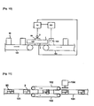
- Fig. 10 provides a side view, a front view, a flat view, and a bottom view each illustrating an appearance of a packaging container and an unsealing apparatus for the container according to a second embodiment of the present invention.
- Fig. 11 is a general front view illustrating the model shown in FIG. 10 in which an inspection apparatus according to a third embodiment of the present invention is incorporated in a production line.
- the inspection apparatus is used for inspection of an opening 2 of a web-like laminated packaging material having a thermoplastic material outermost layer, a paper-made substrate layer, a conductive barrier layer, and a heat-sealable innermost layer.
- the opening 2 is formed by cutting off the thermoplastic material outermost layer, the paper-made substrate layer, the conductive barrier layer, and the heat-sealable innermost layer, and is sealed in the easily-openable condition.
- the opening 2 is formed with a through hole provided on the laminated packaging material, and an area including an outré peripheral portion of the through hole is sealed with a pull-tag providing the barrier effect from the outer side and also with a patch film 5 from the inner side. As shown in Fig.
- a probe electrode 3 is provided on the patch film 5 from the inner side.
- a plate-like earth electrode 4 having a length equivalent to a transversal width of the laminating packaging material is provided so that a conductive barrier layer on an end face 6 of the web-like laminated packaging material can be detected.
- the probe electrode and the earth electrode 4 are provided adjacent to each other in the outer side and in the inner side from the opening 3 respectively without mechanically contacting a surface of the laminated packaging material 1. Therefore, an outer surface of the laminated packaging material is not damaged by the electrodes (during inspection), and all products (packaging material and a packaging container) can be inspected on a production line. Operations for detecting a defective sealed condition with the inspection apparatus according to the first embodiment are described with reference to FIG.
- the opening 2 is formed with a through hole provided on the laminated packaging material having a thermoplastic material outer most layer 7, a paper-made substrate layer 8, a conductive barrier layer 9, and a heat-sealable innermost layer 10, and an area including an outer peripheral portion of the through hole is sealed with the pull-tab 1 providing the barrier effect from the outer side and also with the patch film 5 from the inner side.
- the conductive barrier layer is used for inspection, and conductivity of the barrier layer is utilized.
- a high voltage power line 12 is connected to a section between the probe electrode 3 and the earth electrode 4, and a high voltage is applied to the section.
- a determining unit 13 detects conduction between the probe electrode 3 and the conductive barrier layer 9 provided on an end face of the through hole via the pin hole 14 on the patch film 5 to determine whether the sealed condition is defective or not.
- the probe electrode and the conductive barrier layer provided on an end face of the through hole are electrically connected to each other via the pin hole and furthermore inside of the conductive barrier layer is energized. Because the earth electrode is provided so that the conductive barrier layer on an end face of the web-like laminated packaging material can be detected, and therefore when there is any pin hole, an electric current flows between the probe electrode and the earth electrode via the conductive barrier layer.
- the probe electrode 3 is pyriform and has a form covering up to an outer peripheral portion of the through hole. Therefore, even when a pin hole is present in the heat-sealable innermost layer at a position 15 off from the outer peripheral portion of the through hole, an electric current does not flow between the probe electrode 3 and the earth electrode 4, so that a malfunction of detecting a not-defective condition as a defective condition can be prevented.
- FIG. 5 showing an appearance of an inspection apparatus according to a second embodiment of the present invention
- FIG. 6 which is an enlarged view of FIG. 5
- the opening 2 is formed with a through hole provided on the paper-made substrate layer 8, and an area including the through hole is sealed by laminating the thermoplastic material outermost layer 7, the conductive barrier layer 9, and the heat-sealable innermost layer 19. Because of the configuration as described above, an opening can be inspected before the packaging material is formed into a container and a liquid content is filled in the container, namely, for instance, before the filling step with a packaging/filling machine shown in FIG. 3 is started.
- the probe electrode 3 is shown in a simplified condition in FIG. 6
- the probe electrode has a form covering up to at least a peripheral portion of the through hole.
- a form the probe electrode 3 is shown in FIG. 7 .
- the electrode 3 has a circular form covering a peripheral portion 72 of a through hole 71.
- the probe electrode 3 is provided on the heat-sealable innermost layer 10 from the inner side. Therefore, even when a pin hole is present in the heat-sealable innermost layer at a position 15 off from the outer peripheral portion of the through hole, an electric current does not flow between the probe electrode 3 and the earth electrode 4, so that a malfunction of detecting a not-defective condition as a defective condition can be prevented.
- the determining unit 13 detects a conductive condition caused by a void 14 penetrating the thermoplastic material outermost layer 7, the conductive barrier layer 9, and the heat-sealable innermost layer inside the through hole to determine whether the sealed condition is defective or not.
- the opening 2 at a vertex 21 of a container 80 with a content 81 filled therein is formed with a through hole on the paper-made substrate layer 8, and an area including the through hole is sealed by laminating the thermoplastic material outermost layer 7, the conductive barrier layer 9, and the heat-sealable innermost layer 10.
- the probe electrode 3 having a form covering up to at least a peripheral portion of the through hole is provided on the thermoplastic material outermost layer 7 from the outer side.
- the earth electrode 4 is provided so that the conductive barrier layer 9 provided on an end face 82 of the laminated packaging material having been formed into a container can be detected.
- the earth electrode 4 having a plate-like form is provided so that the earth electrode 4 contacts a bottom of the container.
- the high voltage power line 12 is connected to a section between the probe electrode 3 and the earth electrode 4 and a high voltage is applied to the section.
- the void 14 penetrating the thermoplastic material outermost layer 7, the conductive barrier layer 9, and the heat-sealable innermost layer 10 inside the through hole.
- the conductive barrier layer 9 is exposed on an end face of the void or the pin hole, and the determining unit 13 detects the electric connection to determine that the sealed condition is defective.
- inspection is performed after a final product is manufactured. Because of the feature, a product with high reliability can be shipped.
- FIG. 9 illustrates a variant.
- the opening 2 provided at a vertex of the container 80 is sealed by laminating the thermoplastic material outermost layer 7, the conductive barrier layer 9, and the heat-sealable innermost layer 10.
- the probe electrode 3 is provided from the outer side from the opening 2.
- the earth electrode 4 is provided so that the conductive barrier layer 9 provided on an end face of the laminated packaging material having been formed into a container can be detected.
- the earth electrode 4 made of a fibrous metal is provided so that the earth electrode 4 contacts a bottom of the container.
- the high voltage power line 12 is connected to a section between the probe electrode 3 and the earth electrode 4, and a high voltage is applied to the section.
- FIG 1o and FIG. 11 each illustrate a model in which the inspection apparatus according to the third embodiment of the present invention is incorporated in a production line.
- the containers 80 are successively transferred by a belt conveyor 101.
- a vertical conveyor 102 for transferring each container 80 gripping from the side face side is provided on the way of the line, and the probe electrode 3 is provided above the vertical conveyor 102 and the earth electrode 4 is provided under the vertical conveyor 102.
- the determining unit detects the electrically connected condition to determine that the sealed condition is defective.
- a defective product take-out device 103 activates a pusher 104 to remove the defective container from the production line.
- the packaging container according to the present invention can be applied to a packaging container with a liquid food such as juice or milk filled therein.
Landscapes
- General Physics & Mathematics (AREA)
- Physics & Mathematics (AREA)
- Chemical & Material Sciences (AREA)
- Life Sciences & Earth Sciences (AREA)
- Health & Medical Sciences (AREA)
- General Health & Medical Sciences (AREA)
- Analytical Chemistry (AREA)
- Biochemistry (AREA)
- Immunology (AREA)
- Pathology (AREA)
- Electrochemistry (AREA)
- Chemical Kinetics & Catalysis (AREA)
- Engineering & Computer Science (AREA)
- Food Science & Technology (AREA)
- Medicinal Chemistry (AREA)
- Examining Or Testing Airtightness (AREA)
- Other Investigation Or Analysis Of Materials By Electrical Means (AREA)
- Investigating Or Analyzing Materials By The Use Of Electric Means (AREA)
Claims (4)
- Verfahren zur Inspektion einer Öffnung (2), welche an einem laminierten Verpackungsmaterial (1) vorgesehen ist, welches eine thermoplastische äußerste Schicht (7), eine aus Papier hergestellte Substratschicht (8), eine leitende Barriereschicht (9) und eine heißsiegelbare innerste Schicht (10) aufweist, wobei die Öffnung (2) durch teilweises Schneiden wenigstens der thermoplastischen äußersten Schicht und der aus Papier hergestellten Substratschicht angefertigt wird und auch die Öffnung (2) in dem leicht zu öffnenden Zustand versiegelt ist, wobei
eine Sondenelektrode (3) und eine Erdungselektrode (4) außerhalb und innerhalb der Öffnung (2) vorgesehen sind, wobei
die Sondenelektrode (3) keinen mechanischen Kontakt mit einer Oberfläche des laminierten Verpackungsmaterials (1) hat;
eine hohe Spannung zwischen der Sondenelektrode (3) und der Erdungselektrode (4) geladen bzw. angelegt wird und ein Strom, welcher zwischen der Sondenelektrode (3) und der Erdungselektrode (4) über die leitende Sperrschicht (9) fließt, festgestellt wird; und
ein versiegelter Zustand der Öffnung (2) durch eine Bestimmungseinheit inspiziert wird. - Versiegelungszustandsinpektionsverfahren nach Anspruch 1, wobei die Öffnung (2) mit einem Durchgangsloch gebildet wird, welches an einem laminierten Verpackungsmaterial (1) vorgesehen ist, und ein Bereich beinhaltend einen äußeren peripheren Abschnitt des Durchgangsloches mit einem als Barriere wirkenden Abziehetikett von der Außenseite und mit einer Verstärkungsfolie von der Innenseite versiegelt wird;
die Sondenelektrode (3) eine Form aufweist, welche bis zu einem äußeren peripheren Abschnitt des Durchgangsloches abdeckt und an der Verstärkungsfolie von der Innenseite vorgesehen ist;
die Erdungselektrode (4) derart vorgesehen ist, dass die leitende Sperrschicht (9) an wenigstens einer Stirnseite des bahnartigen laminierten Verpackungsmaterials (1) festgestellt werden kann; und
die Bestimmungseinheit Leitung zwischen der Sondenelektrode (3) und der leitenden Sperrschicht (9) an der Stirnseite des Durchgangsloches über die Verstärkungsfolie feststellt, um zu bestimmen, ob der versiegelte Zustand fehlerhaft ist oder nicht. - Versiegelungszustandsinpektionsverfahren nach Anspruch 1 oder 2, wobei die Öffnung mit einem Durchgangsloch gebildet wird, welches auf der aus Papier hergestellten Substratschicht (8) vorgesehen ist, und ein Bereich beinhaltend das Durchgangsloch durch Laminieren der äußersten Schicht (7) aus thermoplastischem Material, der leitenden Sperrschicht (9) und der heißsiegelbaren innersten Schicht (10) versiegelt wird;
die Sondenelektrode (3) eine Form aufweist, welche wenigstens einen äußeren peripheren Abschnitt des Durchgangslochs abdeckt und an der heißsiegelbaren innersten Schicht (10) von der Innenseite vorgesehen ist; die Erdungselektrode (4) eine Form aufweist, welche bis zu einem äußeren peripheren Abschnitt des Durchgangslochs abdeckt und an der äußersten Schicht (7) aus thermoplastischem Material von der Außenseite vorgesehen ist; und
die Bestimmungseinheit Leitung feststellt durch eine Leere, welche die äußerste Schicht (7) aus thermoplastischem Material, die leitende Sperrschicht (9) und die heißsiegelbare innerste Schicht (10) in dem Durchgangsloch durchdringt, um zu bestimmen, ob der versiegelte Zustand fehlerhaft ist oder nicht. - Versiegelungszustandsinpektionsverfahren nach einem der vorhergehenden Ansprüche, wobei
die Öffnung (2), welche an einem Scheitelabschnitt eines Behälters vorgesehen ist, mit einem Durchgangsloch gebildet wird, welches an der aus Papier hergestellten Substratschicht (8) vorgesehen ist, und ein Bereich beinhaltend das Durchgangsloch durch Laminieren der äußersten Schicht (7) aus thermoplastischem Material, der leitenden Sperrschicht (9) und der heißsiegelbaren innersten Schicht (10) versiegelt wird;
die Sondenelektrode (3) eine Form aufweist, welche wenigstens einen äußeren peripheren Abschnitt des Durchgangslochs abdeckt und an der thermoplastischen äußersten Schicht (7) von der Außenseite vorgesehen ist;
die Erdungselektrode (4) derart vorgesehen ist, dass die leitende Sperrschicht (9), welche vorgesehen ist an wenigstens einer Stirnseite des laminierten Verpackungsmaterials (9), welches zu dem Behälter gebildet wird, festgestellt werden kann; und
die Bestimmungseinheit Leitung feststellt über die Leitungssperre durch eine Leere, welche die äußerste Schicht (7) aus thermoplastischem Material, die leitende Sperrschicht (9) und die heißsiegelbare innerste Schicht (10) innerhalb des Durchgangsloches durchdringt, um zu bestimmen, ob der versiegelte Zustand fehlerhaft ist oder nicht.
Applications Claiming Priority (2)
| Application Number | Priority Date | Filing Date | Title |
|---|---|---|---|
| JP2005366010A JP4698405B2 (ja) | 2005-12-20 | 2005-12-20 | シール状態検査装置及びシール状態検査方法 |
| PCT/JP2006/324933 WO2007072729A1 (ja) | 2005-12-20 | 2006-12-14 | シール状態検査装置及びシール状態検査方法 |
Publications (3)
| Publication Number | Publication Date |
|---|---|
| EP1965207A1 EP1965207A1 (de) | 2008-09-03 |
| EP1965207A4 EP1965207A4 (de) | 2010-09-15 |
| EP1965207B1 true EP1965207B1 (de) | 2013-03-06 |
Family
ID=38188510
Family Applications (1)
| Application Number | Title | Priority Date | Filing Date |
|---|---|---|---|
| EP06834687A Not-in-force EP1965207B1 (de) | 2005-12-20 | 2006-12-14 | Versiegelungszustandinspektionsvorrichtung und - verfahren |
Country Status (6)
| Country | Link |
|---|---|
| US (1) | US8104363B2 (de) |
| EP (1) | EP1965207B1 (de) |
| JP (1) | JP4698405B2 (de) |
| CN (1) | CN101341400B (de) |
| BR (1) | BRPI0620214A2 (de) |
| WO (1) | WO2007072729A1 (de) |
Families Citing this family (15)
| Publication number | Priority date | Publication date | Assignee | Title |
|---|---|---|---|---|
| JP4698406B2 (ja) * | 2005-12-20 | 2011-06-08 | 日本テトラパック株式会社 | シール状態検査装置及びシール状態検査方法 |
| BR112013015409A2 (pt) * | 2010-12-29 | 2016-09-20 | Tetra Laval Holdings & Finance | método e dispositivo para detecção de defeitos em um laminado de embalagem |
| DE102012207736B4 (de) * | 2012-05-09 | 2023-05-17 | Syntegon Technology Gmbh | Vorrichtung und Verfahren zum Fördern gefüllter Behälter und Prüfen derselben auf ausgetretene Flüssigkeit |
| KR102043179B1 (ko) * | 2013-02-18 | 2019-11-12 | 삼성디스플레이 주식회사 | 배리어 막의 결함 검출 방법 및 배리어 막의 결함 검출 장치 |
| US9354090B2 (en) * | 2013-05-22 | 2016-05-31 | Honeywell Limited | Scanning sensor arrangement for paper machines or other systems |
| US9796274B2 (en) | 2013-05-22 | 2017-10-24 | Honeywell Limited | Power delivery system for providing power to sensor head of paper machine or other system |
| CN104062232B (zh) * | 2014-07-17 | 2017-04-05 | 济南兰光机电技术有限公司 | 一种热封参数及强度检测系统及方法 |
| GB2532797A (en) * | 2014-11-28 | 2016-06-01 | Clifton Packaging Group Ltd | A food product and methods of packaging raw wet protein for retail |
| CN105004495B (zh) * | 2015-07-02 | 2017-07-18 | 高田(长兴)汽车安全装置有限公司 | 气体发生器出气口铝箔贴附密封性检测装置及其检测方法 |
| DE102015118287B3 (de) | 2015-10-27 | 2017-01-12 | Intravis Gmbh | Verfahren und Vorrichtung zur Prüfung von Prüfobjekten auf das Vorliegen von Beschädigungen |
| CN106742697B (zh) * | 2017-01-23 | 2025-07-22 | 北京数码通科技有限公司 | 一种制作包材结构的生产方法、包材结构及产品包装 |
| CN106989878B (zh) * | 2017-05-17 | 2023-09-05 | 浙江环球滤清器有限公司 | 外密件漏装检测组件 |
| CN109624397B (zh) * | 2018-12-27 | 2021-05-07 | 江苏美嘉包装有限公司 | 一种酒盒加工用涂胶压平设备及其加工方法 |
| EP3782760A1 (de) * | 2019-08-22 | 2021-02-24 | Linde GmbH | Brenner zum lichtbogenschweissen oder schneiden und verfahren mit diesem brenner |
| EP4435414A1 (de) * | 2023-03-24 | 2024-09-25 | Tetra Laval Holdings & Finance S.A. | Verfahren zur erkennung von anomalien in einer öffnungsvorrichtung |
Family Cites Families (33)
| Publication number | Priority date | Publication date | Assignee | Title |
|---|---|---|---|---|
| US3254526A (en) * | 1964-01-27 | 1966-06-07 | Sinclair Research Inc | Method and apparatus of testing fluidimpermeable films for holes |
| BE795830A (fr) * | 1972-03-06 | 1973-06-18 | Baxter Laboratories Inc | Procede pour verifier des dispositifs membraneux quant a la presence de fuites |
| US3937064A (en) * | 1975-01-17 | 1976-02-10 | Baxter Laboratories, Inc. | Membrane leak checking technique |
| US4728800A (en) * | 1985-04-24 | 1988-03-01 | Young Engineering, Inc. | Apparatus and method for detecting defects in a moving web |
| US4768371A (en) * | 1985-12-06 | 1988-09-06 | Ceramatec, Inc. | Leak detector |
| JPH06171620A (ja) * | 1992-07-29 | 1994-06-21 | Nippon North Kk | 流体包装品の漏れ検出装置 |
| CN1162741A (zh) * | 1996-02-16 | 1997-10-22 | 乔维恩电机株式会社 | 密封包装物的检查方法 |
| JP3137591B2 (ja) * | 1996-12-04 | 2001-02-26 | 太陽工業株式会社 | 導電層を有するシートの接合部の検査方法 |
| JP4057139B2 (ja) * | 1998-04-16 | 2008-03-05 | 日本テトラパック株式会社 | 損傷検出装置 |
| JP2000088788A (ja) * | 1998-07-10 | 2000-03-31 | Jiyooben Denki Kk | 密封包装物の検査方法 |
| FI990159A7 (fi) * | 1999-01-28 | 2000-07-29 | Metso Paper Automation Oy | Menetelmä kuiturainan laadun valvomiseksi |
| JP4223620B2 (ja) * | 1999-03-03 | 2009-02-12 | 株式会社インテリジェントセンサーテクノロジー | 漏れ検出方法及び漏れ検出装置 |
| JP3494585B2 (ja) * | 1999-03-10 | 2004-02-09 | ジョーベン電機株式会社 | 密封包装物の検査方法 |
| DK1057619T3 (da) * | 1999-05-14 | 2004-07-05 | Tetra Laval Holdings & Finance | Fejldetektor til emballagelukninger |
| JP2002202277A (ja) * | 2000-12-27 | 2002-07-19 | Nihon Tetra Pak Kk | 損傷検出装置 |
| US6792807B2 (en) * | 2001-04-23 | 2004-09-21 | Cmd Corporation | Method and apparatus for sensing a seal on a film |
| JP4802420B2 (ja) * | 2001-08-30 | 2011-10-26 | 東洋製罐株式会社 | 多層フィルムの欠陥検出装置 |
| JP4867108B2 (ja) * | 2001-08-30 | 2012-02-01 | 東洋製罐株式会社 | 袋状容器の製造装置 |
| US6895811B2 (en) * | 2001-12-14 | 2005-05-24 | Shawmut Corporation | Detection of small holes in laminates |
| JP2004101412A (ja) * | 2002-09-11 | 2004-04-02 | Dainippon Printing Co Ltd | スカイブヘミング加工部のピンホール欠陥検査装置 |
| JP2004132714A (ja) * | 2002-10-08 | 2004-04-30 | Nihon Tetra Pak Kk | 品質検査方法及び品質検査装置 |
| JP2004132713A (ja) * | 2002-10-08 | 2004-04-30 | Nihon Tetra Pak Kk | 品質検査方法及び品質検査装置 |
| JP3818954B2 (ja) * | 2002-10-22 | 2006-09-06 | 日本テトラパック株式会社 | 容器検査方法及び容器検査装置 |
| US6840108B2 (en) * | 2003-01-08 | 2005-01-11 | Packaging Technologies & Inspection Llc | Method and apparatus for airborne ultrasonic testing of package and container seals |
| UA64623C2 (en) * | 2003-07-25 | 2005-03-15 | Subsidiary Entpr With Foreign | Method for nondestructive testing the tightness of an article using gas discharge |
| JP2005121054A (ja) * | 2003-10-14 | 2005-05-12 | Nihon Tetra Pak Kk | 包材検査装置 |
| US7030400B2 (en) * | 2003-12-30 | 2006-04-18 | Xerox Corporation | Real-time web inspection method and apparatus using combined reflected and transmitted light images |
| US7623699B2 (en) * | 2004-04-19 | 2009-11-24 | 3M Innovative Properties Company | Apparatus and method for the automated marking of defects on webs of material |
| JP4405850B2 (ja) * | 2004-05-14 | 2010-01-27 | 日本テトラパック株式会社 | シール検査方法及びシール検査装置 |
| JP4726001B2 (ja) * | 2005-12-20 | 2011-07-20 | 日本テトラパック株式会社 | シール状態検査装置及びシール状態検査方法 |
| JP4698406B2 (ja) * | 2005-12-20 | 2011-06-08 | 日本テトラパック株式会社 | シール状態検査装置及びシール状態検査方法 |
| JP5105505B2 (ja) * | 2006-12-19 | 2012-12-26 | 日本テトラパック株式会社 | 容器検査方法及び容器検査装置 |
| US7649365B1 (en) * | 2007-03-24 | 2010-01-19 | Kla-Tencor Corporation | Inline inspection of photovoltaics for electrical defects |
-
2005
- 2005-12-20 JP JP2005366010A patent/JP4698405B2/ja not_active Expired - Fee Related
-
2006
- 2006-12-14 CN CN2006800481607A patent/CN101341400B/zh not_active Expired - Fee Related
- 2006-12-14 BR BRPI0620214-4A patent/BRPI0620214A2/pt not_active Application Discontinuation
- 2006-12-14 EP EP06834687A patent/EP1965207B1/de not_active Not-in-force
- 2006-12-14 US US12/097,210 patent/US8104363B2/en not_active Expired - Fee Related
- 2006-12-14 WO PCT/JP2006/324933 patent/WO2007072729A1/ja not_active Ceased
Also Published As
| Publication number | Publication date |
|---|---|
| EP1965207A1 (de) | 2008-09-03 |
| BRPI0620214A2 (pt) | 2013-01-15 |
| JP4698405B2 (ja) | 2011-06-08 |
| US8104363B2 (en) | 2012-01-31 |
| WO2007072729A1 (ja) | 2007-06-28 |
| CN101341400A (zh) | 2009-01-07 |
| CN101341400B (zh) | 2012-01-11 |
| JP2007170893A (ja) | 2007-07-05 |
| US20090165536A1 (en) | 2009-07-02 |
| EP1965207A4 (de) | 2010-09-15 |
Similar Documents
| Publication | Publication Date | Title |
|---|---|---|
| EP1965207B1 (de) | Versiegelungszustandinspektionsvorrichtung und - verfahren | |
| JP3818954B2 (ja) | 容器検査方法及び容器検査装置 | |
| KR100655567B1 (ko) | 유동성 식료품의 무균성 밀봉 포장 제품을 제조하기 위한 스트립 포장재 중의 각각의 개구에 적용된 착탈가능한 폐쇄 장치의 무결성을 검사하기 위한 제어 장치 | |
| JP3818952B2 (ja) | 品質検査方法及び品質検査装置 | |
| JP4726001B2 (ja) | シール状態検査装置及びシール状態検査方法 | |
| US6029421A (en) | Method of quality control and appropriately prepared packaging container and blank | |
| JP2007170894A5 (de) | ||
| JP2000035373A (ja) | フレキシブルパウチの検査機および検査方法 | |
| AU2002219537B2 (en) | Flaw detector | |
| JP4698406B2 (ja) | シール状態検査装置及びシール状態検査方法 | |
| JP2009236505A (ja) | 容器のシール不良検査方法 | |
| JP2004132713A (ja) | 品質検査方法及び品質検査装置 | |
| JP5105505B2 (ja) | 容器検査方法及び容器検査装置 | |
| JP2006084362A (ja) | シール状態検査装置 | |
| JP3948732B2 (ja) | 品質検査方法 | |
| JP4795090B2 (ja) | 包材検査装置 | |
| JPH10132776A (ja) | 積層蓋体の金属露出の検出方法 | |
| JP2004136911A (ja) | 被検体調製方法及び被検体調製装置 | |
| JP2014199236A (ja) | 紙容器用シール検査装置 | |
| JP2010163204A (ja) | シール不良検査可能な密封容器の製造方法 | |
| JP2008230683A (ja) | 包装充填装置及び包装充填方法 |
Legal Events
| Date | Code | Title | Description |
|---|---|---|---|
| PUAI | Public reference made under article 153(3) epc to a published international application that has entered the european phase |
Free format text: ORIGINAL CODE: 0009012 |
|
| 17P | Request for examination filed |
Effective date: 20080612 |
|
| AK | Designated contracting states |
Kind code of ref document: A1 Designated state(s): DE FR GB IT |
|
| DAX | Request for extension of the european patent (deleted) | ||
| RBV | Designated contracting states (corrected) |
Designated state(s): DE FR GB IT |
|
| A4 | Supplementary search report drawn up and despatched |
Effective date: 20100813 |
|
| RIC1 | Information provided on ipc code assigned before grant |
Ipc: G01M 3/16 20060101ALI20100809BHEP Ipc: G01N 27/92 20060101AFI20070816BHEP Ipc: B31B 1/74 20060101ALI20100809BHEP |
|
| 17Q | First examination report despatched |
Effective date: 20110620 |
|
| RAP1 | Party data changed (applicant data changed or rights of an application transferred) |
Owner name: TETRA LAVAL HOLDINGS & FINANCE S.A. |
|
| REG | Reference to a national code |
Ref country code: DE Ref legal event code: R079 Ref document number: 602006034959 Country of ref document: DE Free format text: PREVIOUS MAIN CLASS: G01N0027920000 Ipc: G01M0003320000 |
|
| RIC1 | Information provided on ipc code assigned before grant |
Ipc: G01M 3/32 20060101ALI20120911BHEP Ipc: G01N 27/20 20060101ALI20120911BHEP Ipc: G01N 27/92 20060101AFI20120911BHEP Ipc: G01M 3/40 20060101ALI20120911BHEP Ipc: B31B 1/74 20060101ALI20120911BHEP Ipc: G01M 3/16 20060101ALI20120911BHEP |
|
| GRAP | Despatch of communication of intention to grant a patent |
Free format text: ORIGINAL CODE: EPIDOSNIGR1 |
|
| RIC1 | Information provided on ipc code assigned before grant |
Ipc: G01M 3/32 20060101AFI20120918BHEP Ipc: G01M 3/40 20060101ALI20120918BHEP Ipc: G01N 27/20 20060101ALI20120918BHEP |
|
| GRAS | Grant fee paid |
Free format text: ORIGINAL CODE: EPIDOSNIGR3 |
|
| GRAA | (expected) grant |
Free format text: ORIGINAL CODE: 0009210 |
|
| AK | Designated contracting states |
Kind code of ref document: B1 Designated state(s): DE FR GB IT |
|
| REG | Reference to a national code |
Ref country code: GB Ref legal event code: FG4D |
|
| REG | Reference to a national code |
Ref country code: DE Ref legal event code: R096 Ref document number: 602006034959 Country of ref document: DE Effective date: 20130425 |
|
| PLBE | No opposition filed within time limit |
Free format text: ORIGINAL CODE: 0009261 |
|
| STAA | Information on the status of an ep patent application or granted ep patent |
Free format text: STATUS: NO OPPOSITION FILED WITHIN TIME LIMIT |
|
| 26N | No opposition filed |
Effective date: 20131209 |
|
| REG | Reference to a national code |
Ref country code: DE Ref legal event code: R097 Ref document number: 602006034959 Country of ref document: DE Effective date: 20131209 |
|
| REG | Reference to a national code |
Ref country code: FR Ref legal event code: PLFP Year of fee payment: 10 |
|
| REG | Reference to a national code |
Ref country code: FR Ref legal event code: PLFP Year of fee payment: 11 |
|
| PGFP | Annual fee paid to national office [announced via postgrant information from national office to epo] |
Ref country code: FR Payment date: 20161111 Year of fee payment: 11 Ref country code: GB Payment date: 20161214 Year of fee payment: 11 Ref country code: DE Payment date: 20161206 Year of fee payment: 11 |
|
| PGFP | Annual fee paid to national office [announced via postgrant information from national office to epo] |
Ref country code: IT Payment date: 20161221 Year of fee payment: 11 |
|
| REG | Reference to a national code |
Ref country code: DE Ref legal event code: R119 Ref document number: 602006034959 Country of ref document: DE |
|
| GBPC | Gb: european patent ceased through non-payment of renewal fee |
Effective date: 20171214 |
|
| REG | Reference to a national code |
Ref country code: FR Ref legal event code: ST Effective date: 20180831 |
|
| PG25 | Lapsed in a contracting state [announced via postgrant information from national office to epo] |
Ref country code: IT Free format text: LAPSE BECAUSE OF NON-PAYMENT OF DUE FEES Effective date: 20171214 Ref country code: FR Free format text: LAPSE BECAUSE OF NON-PAYMENT OF DUE FEES Effective date: 20180102 Ref country code: DE Free format text: LAPSE BECAUSE OF NON-PAYMENT OF DUE FEES Effective date: 20180703 |
|
| PG25 | Lapsed in a contracting state [announced via postgrant information from national office to epo] |
Ref country code: GB Free format text: LAPSE BECAUSE OF NON-PAYMENT OF DUE FEES Effective date: 20171214 |