EP1966067B1 - Vorrichtung zur einstellung von spuren auf einem fliessband - Google Patents
Vorrichtung zur einstellung von spuren auf einem fliessband Download PDFInfo
- Publication number
- EP1966067B1 EP1966067B1 EP06847109A EP06847109A EP1966067B1 EP 1966067 B1 EP1966067 B1 EP 1966067B1 EP 06847109 A EP06847109 A EP 06847109A EP 06847109 A EP06847109 A EP 06847109A EP 1966067 B1 EP1966067 B1 EP 1966067B1
- Authority
- EP
- European Patent Office
- Prior art keywords
- walls
- lanes
- carriage
- conveyor
- shafts
- Prior art date
- Legal status (The legal status is an assumption and is not a legal conclusion. Google has not performed a legal analysis and makes no representation as to the accuracy of the status listed.)
- Not-in-force
Links
- 238000011144 upstream manufacturing Methods 0.000 claims description 30
- 230000007246 mechanism Effects 0.000 claims description 19
- 230000033001 locomotion Effects 0.000 claims description 8
- 230000000694 effects Effects 0.000 claims description 6
- 238000000926 separation method Methods 0.000 claims 2
- 238000005192 partition Methods 0.000 abstract 2
- 238000011084 recovery Methods 0.000 description 8
- 238000009434 installation Methods 0.000 description 7
- 238000010586 diagram Methods 0.000 description 5
- 238000006073 displacement reaction Methods 0.000 description 5
- 230000008093 supporting effect Effects 0.000 description 5
- 238000012550 audit Methods 0.000 description 3
- 230000008859 change Effects 0.000 description 3
- 230000000295 complement effect Effects 0.000 description 2
- 235000021183 entrée Nutrition 0.000 description 2
- 230000006872 improvement Effects 0.000 description 2
- 239000003607 modifier Substances 0.000 description 2
- 238000004806 packaging method and process Methods 0.000 description 2
- 238000013519 translation Methods 0.000 description 2
- 238000004804 winding Methods 0.000 description 2
- 230000008901 benefit Effects 0.000 description 1
- 230000004087 circulation Effects 0.000 description 1
- 238000007373 indentation Methods 0.000 description 1
- 239000000463 material Substances 0.000 description 1
- 239000002184 metal Substances 0.000 description 1
- 229910052751 metal Inorganic materials 0.000 description 1
- 230000010363 phase shift Effects 0.000 description 1
Images



Classifications
-
- B—PERFORMING OPERATIONS; TRANSPORTING
- B65—CONVEYING; PACKING; STORING; HANDLING THIN OR FILAMENTARY MATERIAL
- B65G—TRANSPORT OR STORAGE DEVICES, e.g. CONVEYORS FOR LOADING OR TIPPING, SHOP CONVEYOR SYSTEMS OR PNEUMATIC TUBE CONVEYORS
- B65G21/00—Supporting or protective framework or housings for endless load-carriers or traction elements of belt or chain conveyors
- B65G21/20—Means incorporated in, or attached to, framework or housings for guiding load-carriers, traction elements or loads supported on moving surfaces
- B65G21/2045—Mechanical means for guiding or retaining the load on the load-carrying surface
- B65G21/2063—Mechanical means for guiding or retaining the load on the load-carrying surface comprising elements not movable in the direction of load-transport
- B65G21/2072—Laterial guidance means
-
- B—PERFORMING OPERATIONS; TRANSPORTING
- B65—CONVEYING; PACKING; STORING; HANDLING THIN OR FILAMENTARY MATERIAL
- B65G—TRANSPORT OR STORAGE DEVICES, e.g. CONVEYORS FOR LOADING OR TIPPING, SHOP CONVEYOR SYSTEMS OR PNEUMATIC TUBE CONVEYORS
- B65G2201/00—Indexing codes relating to handling devices, e.g. conveyors, characterised by the type of product or load being conveyed or handled
- B65G2201/02—Articles
- B65G2201/0235—Containers
- B65G2201/0244—Bottles
Definitions
- the present invention relates to a corridor adjusting device which is arranged on a conveyor for guiding objects such as, for example, bottles, according to the preamble of claim 1.
- corridors meet in all applications that require the arrival of products or objects on multiple channels.
- these corridors are used on packaging machines and / or palletizing objects of the bottle type. They allow precise positioning of these bottles on several lines, for their gripping, for example, by means of an appropriate handling tool.
- the document EP 1507722 describes a device that allows to adapt at will, and simultaneously, the width of the corridors on a conveyor for transporting bottles, cans or other.
- the present invention provides an improvement to this type of installation that improves its universal character.
- the system for coordinating the width adjustment of the walls comprises means for rapidly changing the position of a side wall and for retracting it, which means are arranged at the end of the wall. corresponding rod and in particular on the lever, which lever comprises a push button which cooperates with a notch arranged on said connecting rod, the latter further comprising a stop which makes it easy to return to the initial setting.
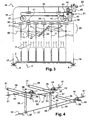
- the figure 1 represents a system of corridors (1) which is installed at the end of a conveyor (2) such as, for example, an endless belt type conveyor (3), whose upper strand, which is only visible in said figure, carries and drives objects of the bottle type (4), which bottles (4) advance in the different corridors (1) in the direction represented by the arrow (5).
- a conveyor (2) such as, for example, an endless belt type conveyor (3), whose upper strand, which is only visible in said figure, carries and drives objects of the bottle type (4), which bottles (4) advance in the different corridors (1) in the direction represented by the arrow (5).
- the belt (3) slides on a sole (6) which is part of the general structure of the conveyor (2) and is driven conventionally by means of a gear motor (7) which is arranged at the upstream end of said conveyor (2), on one of the flanks (8) of the structure of the latter.
- This system of corridors is generally located at a post (10) of recovery in a packaging installation and / or palletizing bottles (4), for example.
- the bottles (4) are ordered to be taken up by appropriate means, not shown, of the type of gripping heads, which heads are associated with a handling tool or other.
- the corridor system (1) consists of walls (11) in the form of metal plates, or other materials, which extend in a vertical plane, above the belt (3) of the conveyor, over the entire length of the post office (10) and even well upstream.
- These various gantries (12, 13, 14) are arranged to carry the walls (11) and to maintain their spacing; they comprise, in addition, on the one hand, means that allow to adjust the width of each corridor, that is to say means that adjust the spacing between the different walls (11), so as to adapt easily the installation to the different sizes of bottles (4) and, secondly, means that allow to shift transversely all of said walls (11) forming the corridors relative to the median vertical plane of the conveyor, without changing the width between said corridors.
- This arrangement makes it possible to wedge the corridors relative to the gripping head, in case of change in the latter.
- the height of the gantries (13, 14) upstream is chosen according to the height of the bottles (4) which are on the conveyor (2); the height of the gantry downstream (12) is different because it is simply positioned above the end of the walls (11) to not clutter the space at the post (10) recovery.
- the walls (11) are carried and guided by a system of slides which is integrated in the various boxes (15), which slide system is detailed below, in connection with the figures 3 , 5, 7 to 9 .
- the walls (11) are also integral with an operating mechanism which is actuated by a control member (21); this control member (21) adjusts the spacing of said walls relative to each other and, consequently, to adjust the width of each corridor.
- the walls (11) are also subjected to a second control member (22) which makes it possible to adjust the transversal position of the corridors (1), that is to say their position relative to the plane and to the median longitudinal axis of the conveyor.
- This member (22) makes it possible to make a transverse displacement of all of said lanes (1) without changing their width, so as to be able to guide, as the case may be, queues of bottles or the like, the number of which may vary, passing from an even number to an odd number.
- Each box (15) of the gantries (12, 13, 14) encloses the various means of maneuvering the walls (11) and in particular the system (30) which makes it possible to coordinate and adjust the spacing of these different walls, one by compared to others.
- This coordination system (30) as well as the other control means have been represented in the form of a block diagram, figure 3 , to facilitate understanding of the whole.
- the different guide passages of the bottles (4) are delimited by the walls (11) which are associated with a system of slides to allow their transverse displacement above the belt (3) of the conveyor.
- These walls (11) comprise, at their upper part and at each gantry (12), (13), (14), a slider-shaped guide member (31) which cooperates with a slide (32), which slide is secured to the box (15).
- All the walls (11) are connected to the aforementioned coordination system (30), which system comprises: - a lever (33) which is articulated on one of the walls (11) and in particular on the central wall, and - connecting rods (34) which connect this lever (33) to the other walls (11) disposed on either side of said central wall.
- the different links (34) are parallel to each other and they form, with the lever (33), the two sides of homothetic triangular figures which allow the simultaneous adjustment of the different walls (11) with the same spacing.
- the third side of these triangles is constituted by the line (35) which is parallel to the slide (32), which line passes through the axis of articulation of the lever (33) and by the axes of articulation of the connecting rods (34). ), which axes are arranged on the corresponding walls (11).
- the different connecting rods (34) are arranged in the same plane and this plane is vertical, perpendicular to the longitudinal axis of the conveyor. This arrangement of connecting rods (34) allows free spacing above the walls (11) to intervene, if necessary, bottles that circulate in the corridors, to raise or remove if necessary.
- the drive system comprises an endless belt or chain (36) which is tensioned between two wheels (37, 38), which wheels (37, 38) are mounted on a carriage-like support (39) and one said wheels, the wheel (38), is actuated by means of the control member (21).
- This control member (21), in the form of wheel, is arranged on a housing (40) which is integral with the carriage (39), movable therewith, which housing (40) comprises appropriate means for transmitting the movement to the wheel (38).
- the upper strand and the lower strand of the endless belt or chain (36) are each connected to one of the walls (11) by means of arms (41, 42) respectively, which arms are, for example, linked to the front -later side walls (11) which act as master walls.
- the setting in motion of the wheel (38), by the control member (21) and by the chain (36), causes spacing or bringing the arms (41) and (42) and the main walls closer together. (11), as the case may be, and, by means of the connecting rods (34) and the lever (33), causes an identical movement of spacing or bringing all the other walls (11) which are said walls .
- the carriage (39) is guided in the box (15) by means of another slide system arranged transversely with respect to the conveyor (2), which system will be detailed later in connection with the Figures 6 and 7 .
- This carriage (39) is operated by a control member (22) which makes it possible to move it transversely and which, consequently, makes it possible to move all the walls (11) globally, and this by way of the chain (36), arms (41) and (42), connecting rods (34) and lever (33). It is the entire adjustment mechanism of the width of the walls (11) which move with the carriage (39).
- the carriage (39) comprises, for example, a rack (43) which cooperates with a toothed wheel (44), which toothed wheel (44) is operated by the control member (22).
- the stroke C of the carriage (39), illustrated figure 6 is provided to change the position of the corridors relative to the median axis of the conveyor or rather of its carpet (3); this stroke C is chosen to allow stalling on said axis: - either the wall (11) central, - Or the median plane of one of the two corridors (1) arranged on either side of said wall (11) central.
- This race C is of the order of half of the maximum width of the corridors.
- this drive system consists of the chain (36) endless tensioned between the pairs of wheels (37), (38).
- the wheels (38) arranged in the gantries (13) and (14) are both mounted on the same shaft (23) which is the driving shaft; the wheel (38) disposed at the downstream gantry (12) is mounted on the shaft (24), which shaft (24) is driven by an endless chain (46) stretched between a wheel (47) mounted on said shaft (23) and a wheel (48) mounted on said shaft (24).
- the shaft (23) is operated by the control member (21) which is, for example, associated with a device of the type of return angle (50).
- the shafts (23) and (24) are guided in bearings which are integral with the carriages (39); they move at the same time as the different carriages (39) which carry the pairs of wheels (37, 38).
- the chain (46) is disposed in a housing (25), which housing is guided, at its lower part, directly by the shaft (27) of the other tree system.
- the shaft (24) may comprise, at each of its ends, patellar connections with the wheel ( 38) of the chain (36) and with the wheel (48) of its drive chain (46).
- Extensions of the shafts (23) or (24) are possible to control other operating mechanisms which cooperate with upstream extensions of the walls (11), not shown.
- the tree system that allows the overall translation of the corridors consists of several trees guided in the structure of the various gantries (12), (13), (14).
- the gears (44) of upstream gantries (13) and (14) are mounted on the same shaft (26) which is guided in bearings (51) integral with the box (15) of each of said gantries (13), (14).
- the toothed wheel (44) of the downstream gantry (12) is driven by a shaft (27) which is guided, on the one hand, in a bearing (51) on the casing (15) of said downstream gantry (12) and, on the other hand, in a bearing (52) located on the upright (18) of the gantry (14).
- Each wheel (44) cooperates with a rack (43) of the carriage (39) carrying the drive system walls (11) and in particular the wheels (37) and (38) of the chain (36) endlessly by which is made the adjustment of the width of said corridors.
- the shaft (26) is driven by the actuating member (22) which is associated, for example, with a bevel gear (54).
- the link between the driving shaft (26) and the driven shaft (27) is effected by means of the endless chain (28), which chain is tensioned between the wheels (56) and (57) which are mounted respectively on said shafts (26) and (27).
- FIG. 5 to 9 illustrate, in more detail, the embodiment of the different mechanisms that are integrated in each of the boxes (15), knowing that the box (12) downstream is substantially different because it is the mirror reflection of the boxes (13, 14) located in upstream.
- each wall (11) comprises a slider (31) whose lower end is provided with an axis (59) for the articulation of the corresponding connecting rod (34) or the lever (33); these different axes (59) are parallel to the longitudinal axis of the conveyor and they are substantially at the same level as the upper end of the endless chain (36), which chain is stretched between the two wheels (37) and (38) ), and these wheels (37) and (38) are mounted on the carriage (39).
- the carriage (39) is in the form of a U-section profile and is guided on the vertical edge (60) of the box (15) by means of lights (61) which appear on the figure 6 .
- the figure 7 is an enlarged section of the figure 5 in the form of a block diagram; it shows the box (15) with the carriage (39) which is carried and guided by the vertical rim (60) of the box (15) by means of sliders (62); these slides (62) are guided in each corresponding light (61), visible figure 6 .
- This carriage (39) appears with the wheel (37) which serves to guide the chain (36) endlessly; the lower run of this chain (36) drives one of the walls (11) via the arm (41).
- the figure 8 is a section of the box (15) at the axis (59) of the lever (33); this axis (59) is integral with the lower end of the slider (31) and is located at the central wall (11).
- the entire coordination system that is to say the lever (33) and the rods (34), is located in the upper part of the walls (11) so as not to burden too much the space under the portico and risk to hinder the circulation of the bottles.
- the amplitude of the adjustment of the width of the corridors can be from 60 to 105 mm, for example.
- the figure 9 is a section of the box (15) which passes, on the one hand, at the shaft (23) of the wheel (38) which cooperates with the chain (36) and, on the other hand, at the level of the shaft (26) of the toothed wheel (44) which cooperates with the rack (43).
- This rack (43) is integral with the carriage (39); it is engaged with the toothed wheel (44) and is driven by the shaft (26), which shaft (26) is actuated from the housing (45) and also drives, via the chain ( 38) without end, the shaft (27), as shown figures 1 , 2 and 4 .
- the indentations (64, 64 ') made in the vertical rim (60) of the box (15), which notch (64, 64') allow the shaft (23) to move transversely at the same time as the trolley (39).
- the second indentation (64 '), which appears on the left side of the flange (60), is a special arrangement which can, according to the assembly, allow the passage of the end of the axis of articulation of the wheel (37). ) winding the endless chain (36) which serves to manipulate the two walls (11) masters.
- the figure 10 represents the detail of the fixing of a connecting rod (34) on the lever (33).
- the rod (34) corresponding is secured to the lever (33) by means of a slide assembly.
- the lever (33) has, at its end, a mechanism with a push button (65) which cooperates with a notch arranged on the end of the connecting rod (34).
- This push button (65) makes it possible to unlock said link (34) with respect to the lever (33) and in particular with respect to its axis (66) and to position it in a manner that is adapted to the situation.
- the end of the connecting rod (34) has a stop (67) which makes it easy to return to the initial setting.
- each wall (11) consists of two sections: - a section (11 ') downstream, which is arranged at the recovery station, and- a section (11 ") upstream, which is articulated on said section (11 ') downstream so as to form, with the or adjacent upstream sections (11 "), a kind of mouth or funnel.
- the articulation between the two sections (11 ') and (11 ") is arranged between the two gantries (13) and (14), about an axis which is perpendicular to the plane of movement of the bottles (4), c' that is, to the carpet (3).
- This articulation consists of a hinge (68) disposed at the upper part of the walls (11).
- the lower part of the walls (11) may comprise rod-shaped blades (69) which serve as guides for the bottles (4) in an off-label zone; these blades (69) also act as reinforcements for said walls.
- the ends of the upstream sections (11 ") are manipulated by the operating mechanisms described above, however the upstream wall spacing adjusting mechanism is slightly out of phase with the other mechanisms, i.e. the upstream entrance of the corridors (1) is wider so as to form a true mouth.
- This phase shift is obtained by a different setting of the arms (41) and (42) on the endless chain (36) of the upstream mechanism which is housed in the gantry (14).
- the width at the mouth of said corridors will be of the order of 90 mm.
Landscapes
- Engineering & Computer Science (AREA)
- Mechanical Engineering (AREA)
- Wrapping Of Specific Fragile Articles (AREA)
- Attitude Control For Articles On Conveyors (AREA)
- Intermediate Stations On Conveyors (AREA)
- Chain Conveyers (AREA)
- Auxiliary Devices For And Details Of Packaging Control (AREA)
- Escalators And Moving Walkways (AREA)
- Branching, Merging, And Special Transfer Between Conveyors (AREA)
- Paper (AREA)
- Impression-Transfer Materials And Handling Thereof (AREA)
- Framework For Endless Conveyors (AREA)
Claims (10)
- Vorrichtung zur Einstellung von Gängen (1) zum Führen von Gegenständen vom Typ Flaschen (4) auf einer Fördereinrichtung am Ende einer Anlage, die beispielsweise eine Entnahmestation (10) aufweist, wobei die Vorrichtung einen Mechanismus zum Dirigieren der die verschiedenen Gänge (1) begrenzenden Wände (11) umfasst, und der Mechanismus aus einem System zum koordinierten Antrieb gebildet ist, das auf die Wände (11) einwirkt, um gleichzeitig die Breite der Gänge (1) einzustellen, wobei die Wände (11) auf Querschienen (32) geführt sind, die fest mit über der Fördereinrichtung angeordneten Tragkonstruktionen verbunden sind,
dadurch gekennzeichnet, dass sie Mittel aufweist, um die Gänge (1) quer zur Mittellängsachse der Fördereinrichtung zu verschieben, wobei die Mittel im Bereich jeder Tragkonstruktion aus einem Support in Form eines Schlittens (39) gebildet sind, der zwischen der Tragkonstruktion und dem System zum koordinierten Antrieb der Wände (11) angeordnet ist, und der Schlitten (39) unter dem Einfluss geeigneter Mittel querbeweglich und von einem Schienensystem geführt ist, das im Bereich der Tragkonstruktionen vorgesehen ist, um die Querverschiebung aller Gänge (1) ohne Änderung ihrer Breite vorzunehmen. - Vorrichtung zur Einstellung von Gängen nach Anspruch 1, dadurch gekennzeichnet, dass sie einen Mechanismus zum Dirigieren der verschiedenen, in den Tragkonstruktionen angeordneten Schlitten (39) umfasst, der Verbindungsmittel in Form von Wellen aufweist, die die Schlitten (39) miteinander so verbinden, dass eine zentralisierte Einstellung der Querlage aller Gänge (1) relativ zur mittleren Symmetrieachse der Fördereinrichtung verwirklicht ist.
- Vorrichtung zur Einstellung von Gängen nach Anspruch 2, dadurch gekennzeichnet, dass der Dirigiermechanismus für jeden Schlitten (39) aus einer auf dem Schlitten angeordneten Zahnstange (43) und aus einem von einem Steuerelement (22) angetriebenen Ritzel (44) gebildet ist, wobei das Element (22) über ein System aus Wellen (26), (27) auf jeden Schlitten (39) einwirkt, und die Wellen so angeordnet sind, dass sie den Zugang zu den Gängen (1) nicht versperren.
- Vorrichtung zur Einstellung von Gängen nach einem der Ansprüche 1 bis 3, dadurch gekennzeichnet, dass das Antriebssystem für die Wände (11), mit dem die Breite der Gänge (1) eingestellt werden kann, einen Endlosriemen oder eine Endloskette (36) umfasst, der bzw. die zwischen zwei am Schlitten (39) montierten Wickelrädern (37), (38) gespannt ist, wobei die Kette (36) mit geeigneten unmittelbar an dem Schlitten (39) angeordneten Mitteln angetrieben ist, und ihre beiden Stränge parallel zum Schienensystem (32) zum Führen der Wände (11) verlaufen, wobei die Stränge der Kette (36) jeweils fest mit einer der Wände (11) verbunden sind, und die von der Kette (36) mitbewegten und als Hauptwände bezeichneten Wände (11) die anderen Wände (11) mittels eines Systems (30) zur Koordination ihres Abstands mitbewegen.
- Vorrichtung zur Einstellung von Gängen nach Anspruch 4, dadurch gekennzeichnet, dass das System (30) zur Koordination des Abstands der verschiedenen Wände (11) umfasst: - einen Hebel (33), der gelenkig mit einer der Wände (11) verbunden ist, und - zueinander parallele Stangen (34), die zwischen dem Hebel (33) und jeder der anderen Wände (11) angeordnet sind, mit dem Hebel (33) zwei der Seiten homothetischer dreieckiger Figuren bilden und in derselben Ebene angeordnet sind, die vertikal und rechtwinklig zur Längsachse der Fördereinrichtung verläuft.
- Vorrichtung zur Einstellung von Gängen nach einem der Ansprüche 1 bis 5, dadurch gekennzeichnet, dass jede Tragkonstruktion für die Wände (11) einen Kasten (15) aufweist, in dem die Gesamtheit der Mechanismen zum Führen und Dirigieren der Wände (11) untergebracht werden kann, wobei der Kasten (15) Stützen (17) und (18) zugeordnet ist, die seitlich an der Fördereinrichtung angeordnet sind, und mit diesen Stützen (17) eine Art Gerüst bildet, das sich über der Fördereinrichtung befindet, wobei die Gerüste (12, 13) auf beiden Seiten der Entnahmestation (10) angeordnet sind und das Gestell (14) dem Gestell (13) vorgelagert im Einlaufbereich der Gänge angeordnet ist.
- Vorrichtung zur Einstellung von Gängen nach Anspruch 6, dadurch gekennzeichnet, dass jeder Schlitten (39) an einem Rand (60) des Kastens (15) der Tragkonstruktion geführt wird, wobei die Führung mithilfe waagerechter Löcher (61) erfolgt, die in dem Rand (60) vorgesehen sind, und mithilfe der Gleitelemente (62), die fest mit dem Schlitten (39) verbunden sind.
- Vorrichtung zur Einstellung von Gängen nach Anspruch 6, dadurch gekennzeichnet, dass der Einstellmechanismus zwei Wellensysteme umfasst: - das aus den Wellen (26), (27) zum Dirigieren der Schlitten (39) gebildete System und - ein Wellensystem zum Dirigieren der Wände (11), wobei die Wellensysteme jeweils eine Hauptwelle (23), (26) umfassen, die zwischen den beiden Gerüsten (13), (14) verläuft, und eine getriebene Welle (24), (27), die mit der entsprechenden Hauptwelle über eine Endloskette (28) beziehungsweise (46) verbunden ist, wobei sich die Welle (24) von dem Gerüst (13) bis zu dem hinteren Gerüst (12) erstreckt, und die Kette (46), die zwischen den Wellen (23) und (24) angeordnet ist, in einem Gehäuse (25) läuft, das von der Welle (27) geführt wird, und sich die Welle (27) von dem Gerüst (14) bis zu dem nachgelagerten Gerüst (12) erstreckt, wobei die Wellen ganz allgemein in einem Bereich angeordnet sind, in dem sie einer Bedienperson den Zugang zu den Gängen (1) nicht versperren.
- Vorrichtung zur Einstellung von Gängen nach einem der Ansprüche 1 bis 8, dadurch gekennzeichnet, dass jede Wand (11) aus zwei Abschnitten gebildet ist, die beweglich miteinander verbunden sind: - einen nachgelagerten Abschnitt (11'), der im Bereich der Entnahmestation (10) angeordnet ist, und - einem vorgelagerten Abschnitt (11''), der um eine senkrechte Achse herum derart beweglich mit dem nachgelagerten Abschnitt (11') verbunden ist, dass mit dem oder den angrenzenden Abschnitten (11'') eine Art Öffnung oder Trichter gebildet wird, wobei die vorgelagerten Abschnitte (11'') im Bereich ihres vorgelagerten Endes vom Antriebsystem für die Wände (11) bewegt werden, wobei das Antriebssystem für die Abschnitte (11'') durch eine andere Einstellung zu Beginn relativ zu den anderen Antriebssystemen für die Abschnitte (11') verschoben ist, sodass im Einlaufbereich der vorgelagerten Abschnitte (11'') ein größerer Abstand erreicht wird.
- Vorrichtung zur Einstellung von Gängen nach einem der Ansprüche 5 bis 9, dadurch gekennzeichnet, dass sie Mittel umfasst, um schnell die Stellung einer Seitenwand (11) zu ändern und sie einzuziehen, die Mittel im Bereich des Endes der entsprechenden Stange (34) und insbesondere am Hebel (33) angeordnet sind, wobei der Hebel eine Drucktaste (65) aufweist, die mit Rillen zusammenwirkt, die auf der Stange (34) vorgesehen sind, wobei letztere des Weiteren einen Anschlag (67) aufweist, mit dem einfach in die Eingangseinstellung zurückgekehrt werden kann.
Applications Claiming Priority (2)
| Application Number | Priority Date | Filing Date | Title |
|---|---|---|---|
| FR0513342A FR2895382B1 (fr) | 2005-12-27 | 2005-12-27 | Dispositif pour regler des couloirs sur un convoyeur. |
| PCT/FR2006/002834 WO2007074230A1 (fr) | 2005-12-27 | 2006-12-22 | Dispositif pour regler des couloirs sur un convoyeur |
Publications (3)
| Publication Number | Publication Date |
|---|---|
| EP1966067A1 EP1966067A1 (de) | 2008-09-10 |
| EP1966067B1 true EP1966067B1 (de) | 2009-12-16 |
| EP1966067B8 EP1966067B8 (de) | 2010-05-19 |
Family
ID=37116949
Family Applications (1)
| Application Number | Title | Priority Date | Filing Date |
|---|---|---|---|
| EP06847109A Not-in-force EP1966067B8 (de) | 2005-12-27 | 2006-12-22 | Vorrichtung zur einstellung von spuren auf einem fliessband |
Country Status (10)
| Country | Link |
|---|---|
| US (1) | US7607531B2 (de) |
| EP (1) | EP1966067B8 (de) |
| JP (1) | JP2009521381A (de) |
| CN (1) | CN101351394B (de) |
| AT (1) | ATE452085T1 (de) |
| DE (1) | DE602006011213D1 (de) |
| ES (1) | ES2338466T3 (de) |
| FR (1) | FR2895382B1 (de) |
| PT (1) | PT1966067E (de) |
| WO (1) | WO2007074230A1 (de) |
Families Citing this family (38)
| Publication number | Priority date | Publication date | Assignee | Title |
|---|---|---|---|---|
| FR2899883B1 (fr) * | 2006-04-18 | 2008-07-04 | Sidel Sas | Aiguillage pourvu de caissons fixes modulaires |
| EP1985558B1 (de) * | 2007-04-27 | 2009-11-11 | Mechatronic System Company S.r.l. | Schalter für Produktzufuhrleitungen |
| FR2932466B1 (fr) * | 2008-06-13 | 2010-12-17 | Sidel Participations | Installation de convoyage multivoies |
| DE102008039970A1 (de) * | 2008-08-27 | 2010-03-04 | Krones Ag | Transportvorrichtung und Verfahren zum geordneten Transport von Artikeln |
| FR2936787B1 (fr) * | 2008-10-03 | 2015-02-27 | Sidel Participations | Procede de preparation de lots de produits, bouteilles ou autres, et installation pour sa mise en oeuvre |
| FR2946632B1 (fr) | 2009-06-11 | 2015-05-29 | Sidel Participations | Installation de convoyage comprenant au moins un couloir courbe |
| ES2499465T5 (es) * | 2010-05-21 | 2022-04-01 | Gebo Packaging Solutions Italy Srl | Método y línea para transportar recipientes, en concreto botellas |
| FR2966806B1 (fr) * | 2010-10-28 | 2014-01-17 | Sidel Participations | Installation pour la preparation de lots de produits, du genre flacons, bouteilles ou autres |
| FR2966807B1 (fr) * | 2010-10-28 | 2012-12-14 | Sidel Participations | Unite regulatrice versatile pour flux de recipients |
| IT1403908B1 (it) * | 2011-01-28 | 2013-11-08 | Ocme Srl | Dispositivo ordinatore di articoli, in particolare di bottiglie, flaconi e/o simili contenitori per prodotti alimentari in avanzamento su un piano di avanzamento non facente parte del dispositivo |
| US8499921B1 (en) * | 2012-01-17 | 2013-08-06 | The Procter & Gamble Company | Adjustable guide rail assemblies |
| ES2626445T3 (es) * | 2012-03-14 | 2017-07-25 | I.M.A. Industria Macchine Automatiche S.P.A. | Aparato para mover recipientes |
| CN103640886B (zh) * | 2013-12-17 | 2015-07-22 | 广西梧州双钱实业有限公司 | 一种包装机同步分离装置 |
| DE102014109522A1 (de) * | 2014-07-08 | 2016-01-14 | Krones Aktiengesellschaft | Transportabschnitt |
| US10351355B2 (en) | 2014-08-01 | 2019-07-16 | Douglas Machine Inc. | Auto changeover infeed assembly |
| CA2910774A1 (en) * | 2014-10-29 | 2016-04-29 | Septimatech Group Inc. | Lane adjustment system |
| CN104843444B (zh) * | 2015-05-21 | 2017-08-25 | 江苏比微曼智能科技有限公司 | 一种多部件传送装置 |
| CN105435269B (zh) * | 2015-12-31 | 2019-02-12 | 重庆房地产职业学院 | 一种全自动智能消毒装置 |
| US9988219B2 (en) * | 2016-04-05 | 2018-06-05 | Heraeus Noblelight America Llc | Metal container conveyor systems including diverter mechanisms, and metal container processing systems including the same |
| DE102016206984A1 (de) * | 2016-04-25 | 2017-10-26 | Krones Aktiengesellschaft | Transportvorrichtung für Artikelströme aus jeweils geordnet nacheinander transportierten Artikeln und Verfahren zur Anpassung einer Transportvorrichtung an verschieden breite Artikel |
| CN106005863B (zh) * | 2016-07-19 | 2018-06-05 | 合肥中鼎信息科技股份有限公司 | 一种自动调节异形包装分拣机 |
| DE102016115187A1 (de) * | 2016-08-16 | 2018-02-22 | Krones Aktiengesellschaft | Vorrichtung und Verfahren zum Transportieren und/oder Manipulieren von Stückgütern |
| BR112017001016A2 (pt) * | 2016-12-12 | 2020-10-27 | Sicpa Holding Sa | configuração de trilho guia, esteira transporte e método para transporte de recipientes |
| JP7197508B2 (ja) * | 2017-05-19 | 2022-12-27 | スパン テック エルエルシー | 調節可能なコンベヤベルトガイドレールおよび関連方法 |
| CO2018000148A1 (es) * | 2018-01-09 | 2019-07-10 | Ind Electromecanicas Acuna Ltda | Mecanismo enfilador helicoidal múltiple de ajuste simultáneo |
| TWM564031U (zh) * | 2018-02-14 | 2018-07-21 | 皇將科技股份有限公司 | 輸送機之護瓶調整結構 |
| DE102018205981A1 (de) * | 2018-04-19 | 2019-10-24 | Krones Ag | Formatteil zum Umlenken von Behältern |
| US10640295B1 (en) * | 2018-05-09 | 2020-05-05 | Septimatech Group Inc. | Conveyor assembly including adjustable lane guide elements |
| CN108820303A (zh) * | 2018-07-20 | 2018-11-16 | 廊坊永创包装机械有限公司 | 一种挡杆式双通道膜包机 |
| CN108860728A (zh) * | 2018-08-22 | 2018-11-23 | 歆坤智能装备(昆山)有限公司 | 药瓶分道机构及药瓶整理设备 |
| CN110002178B (zh) * | 2019-04-29 | 2023-10-13 | 北京好运达智创科技有限公司 | 一种成品井字块码垛装置 |
| PL241973B1 (pl) * | 2019-09-03 | 2023-01-02 | Puchalski Wieslaw | Kolektor do transportera powietrznego do ręcznej paletyzacji butelek PET |
| CN113955391A (zh) * | 2021-09-13 | 2022-01-21 | 山东博创重工股份有限公司 | 一种上料输送机 |
| CN113866841A (zh) * | 2021-09-26 | 2021-12-31 | 杭州睿影科技有限公司 | 安检门、安检设备及安检门的控制方法 |
| DE102022123630A1 (de) * | 2022-09-15 | 2024-03-21 | Khs Gmbh | Aufteilvorrichtung zum Aufteilen von Transportgütern, Transportstrecke mit einer solchen Aufteilvorrichtung und Verfahren zum Aufteilen von Transportgütern |
| JP7858520B2 (ja) * | 2022-12-20 | 2026-05-14 | 株式会社クボタ | 豆類選別機 |
| CN116654352B (zh) * | 2023-07-27 | 2023-11-03 | 献县欧联玻璃容器有限公司 | 玻璃瓶输送装置 |
| CN119305808B (zh) * | 2024-12-17 | 2025-04-29 | 内蒙古三胖蛋食品有限公司 | 一种全自动码垛装箱机 |
Family Cites Families (13)
| Publication number | Priority date | Publication date | Assignee | Title |
|---|---|---|---|---|
| US2951574A (en) * | 1959-04-29 | 1960-09-06 | Machinery Service Company | Path adjusting means for conveyors |
| US3767027A (en) * | 1972-07-25 | 1973-10-23 | Jergen Co A | Adjustable guide assembly for feeding bottles and the like to a horizontal moving platform |
| US4432189A (en) * | 1981-06-01 | 1984-02-21 | Standard-Knapp, Inc. | Shifting grid style packer with lane holdback |
| US4880104A (en) * | 1987-10-05 | 1989-11-14 | Kraft, Inc. | Lane adjusting apparatus for bottle guides |
| JPH0741690Y2 (ja) * | 1989-05-26 | 1995-09-27 | 三菱重工業株式会社 | コンベヤのガイド巾調整装置 |
| US5411129A (en) * | 1993-11-10 | 1995-05-02 | B & B Equipment, Inc. | Dual motion divider for non-round bottles |
| JP4020474B2 (ja) * | 1997-11-17 | 2007-12-12 | アサヒビール株式会社 | 物品の整列ガイド装置 |
| ITMI981247A1 (it) * | 1998-06-03 | 1999-12-03 | Ronchipack S R L | Apparecchiatura per la regolazione della posizione relativa di sponde di guida per contenitori in macchine per la formazione di matrici di |
| US6411129B1 (en) * | 2000-10-03 | 2002-06-25 | Semiconductor Components Industries Llc | Logic circuit with output high voltage boost and method of using |
| EP1344730A1 (de) * | 2002-03-11 | 2003-09-17 | BETT SISTEMI s.r.l. | Vorrichtung zum Anbringen von Führungselementen oder Werkzeugen in regelmässigen Abständen |
| DE20208127U1 (de) * | 2002-05-24 | 2003-01-09 | KRONES AG, 93073 Neutraubling | Transportvorrichtung für Behälter |
| EP1375393A1 (de) * | 2002-06-18 | 2004-01-02 | BETT SISTEMI s.r.l. | Vorrichtung zum Anbringen von Führungselementen oder Werkzeugen in regelmässigen Abständen |
| JP2004099282A (ja) * | 2002-09-11 | 2004-04-02 | Morishita Kikai Seisakusho:Kk | 容器整列集積装置における容器通路巾調整装置 |
-
2005
- 2005-12-27 FR FR0513342A patent/FR2895382B1/fr not_active Expired - Fee Related
-
2006
- 2006-12-22 WO PCT/FR2006/002834 patent/WO2007074230A1/fr not_active Ceased
- 2006-12-22 US US12/159,320 patent/US7607531B2/en not_active Expired - Fee Related
- 2006-12-22 ES ES06847109T patent/ES2338466T3/es active Active
- 2006-12-22 CN CN2006800497291A patent/CN101351394B/zh not_active Expired - Fee Related
- 2006-12-22 DE DE602006011213T patent/DE602006011213D1/de active Active
- 2006-12-22 AT AT06847109T patent/ATE452085T1/de not_active IP Right Cessation
- 2006-12-22 PT PT06847109T patent/PT1966067E/pt unknown
- 2006-12-22 EP EP06847109A patent/EP1966067B8/de not_active Not-in-force
- 2006-12-22 JP JP2008548005A patent/JP2009521381A/ja active Pending
Also Published As
| Publication number | Publication date |
|---|---|
| CN101351394B (zh) | 2011-06-22 |
| CN101351394A (zh) | 2009-01-21 |
| JP2009521381A (ja) | 2009-06-04 |
| PT1966067E (pt) | 2010-03-16 |
| WO2007074230A1 (fr) | 2007-07-05 |
| US20090000914A1 (en) | 2009-01-01 |
| FR2895382A1 (fr) | 2007-06-29 |
| US7607531B2 (en) | 2009-10-27 |
| ES2338466T3 (es) | 2010-05-07 |
| DE602006011213D1 (de) | 2010-01-28 |
| EP1966067A1 (de) | 2008-09-10 |
| EP1966067B8 (de) | 2010-05-19 |
| FR2895382B1 (fr) | 2012-07-20 |
| ATE452085T1 (de) | 2010-01-15 |
Similar Documents
| Publication | Publication Date | Title |
|---|---|---|
| EP1966067A1 (de) | Vorrichtung zur einstellung von spuren auf einem fliessband | |
| EP1413530B1 (de) | Maschine zum Bewegen von Behältern vor Prüfungsvorrichtungen | |
| EP2297009B1 (de) | Mehrwegeförderanlage | |
| EP3609814B1 (de) | Kommissionierungssystem | |
| CA2667021C (fr) | Table de repartition de bouteilles a l'entree de couloirs a file unique | |
| EP2331433B1 (de) | Anlage zur herstellung von chargen von produkten, flaschen und dergleichen | |
| EP2632827B1 (de) | Vielseitige regulierungseinheit für einen behälterstrom | |
| FR2490602A1 (fr) | Systeme convoyeur rassemblant | |
| CA1288678C (fr) | Machine d'encaissage pour caisses americaines | |
| EP0893374B1 (de) | Vorrichtung zur Beabstandung und Übergabe von Produkten, die kontinuierlich mit drei Ketten arbeitet | |
| FR3092574A1 (fr) | Système et procédé de manipulation d'articles tels que récipients à boisson ou similaire | |
| FR2462346A1 (fr) | Dispositif transporteur de petites pieces ou petits emballages pour machines a emballer ou analogues | |
| FR2491039A1 (fr) | Machine d'emballage | |
| EP1973819B1 (de) | Verfahren und gruppierstation für einen palettierer | |
| EP0987095B1 (de) | Versenkbare zentrale Zuführvorrichtung für eine Falt-Leimmaschine | |
| FR2810653A1 (fr) | Dispositif accumulateur en u pour reguler le transfert de produits entre un appareil amont et un appareil aval | |
| FR2508013A1 (fr) | Systeme de convoyeur a deux voies | |
| FR2792921A1 (fr) | Repartiteur de produits pour installation de convoyage | |
| FR2889510A1 (fr) | Procede de groupage de caisses sur un convoyeur et dispositif pour sa mise en oeuvre | |
| EP3720794A1 (de) | Herstellung von chargen von produkten zum palettisieren in schichten | |
| FR2639039A1 (fr) | Dispositif de convoyage a palettes | |
| CH367435A (fr) | Procédé et dispositif pour fournir à un dispositif de préhension d'une machine de manutention des groupes d'objects identiques ordonnés par rangées | |
| FR2581046A1 (fr) | Convoyeur continu perfectionne a palettes | |
| EP0491631B1 (de) | Fördereinrichtung, mit Seitenführungseinrichtung mit Synchronantrieb | |
| FR2530201A1 (fr) | Appareil de chargement automatique du volume total d'un vehicule de transport |
Legal Events
| Date | Code | Title | Description |
|---|---|---|---|
| PUAI | Public reference made under article 153(3) epc to a published international application that has entered the european phase |
Free format text: ORIGINAL CODE: 0009012 |
|
| 17P | Request for examination filed |
Effective date: 20080617 |
|
| AK | Designated contracting states |
Kind code of ref document: A1 Designated state(s): AT BE BG CH CY CZ DE DK EE ES FI FR GB GR HU IE IS IT LI LT LU LV MC NL PL PT RO SE SI SK TR |
|
| GRAP | Despatch of communication of intention to grant a patent |
Free format text: ORIGINAL CODE: EPIDOSNIGR1 |
|
| GRAS | Grant fee paid |
Free format text: ORIGINAL CODE: EPIDOSNIGR3 |
|
| GRAA | (expected) grant |
Free format text: ORIGINAL CODE: 0009210 |
|
| AK | Designated contracting states |
Kind code of ref document: B1 Designated state(s): AT BE BG CH CY CZ DE DK EE ES FI FR GB GR HU IE IS IT LI LT LU LV MC NL PL PT RO SE SI SK TR |
|
| REG | Reference to a national code |
Ref country code: GB Ref legal event code: FG4D Free format text: NOT ENGLISH |
|
| REG | Reference to a national code |
Ref country code: CH Ref legal event code: EP |
|
| REG | Reference to a national code |
Ref country code: IE Ref legal event code: FG4D |
|
| REF | Corresponds to: |
Ref document number: 602006011213 Country of ref document: DE Date of ref document: 20100128 Kind code of ref document: P |
|
| REG | Reference to a national code |
Ref country code: PT Ref legal event code: SC4A Free format text: AVAILABILITY OF NATIONAL TRANSLATION Effective date: 20100309 |
|
| REG | Reference to a national code |
Ref country code: NL Ref legal event code: VDEP Effective date: 20091216 |
|
| PG25 | Lapsed in a contracting state [announced via postgrant information from national office to epo] |
Ref country code: FI Free format text: LAPSE BECAUSE OF FAILURE TO SUBMIT A TRANSLATION OF THE DESCRIPTION OR TO PAY THE FEE WITHIN THE PRESCRIBED TIME-LIMIT Effective date: 20091216 Ref country code: LT Free format text: LAPSE BECAUSE OF FAILURE TO SUBMIT A TRANSLATION OF THE DESCRIPTION OR TO PAY THE FEE WITHIN THE PRESCRIBED TIME-LIMIT Effective date: 20091216 Ref country code: SE Free format text: LAPSE BECAUSE OF FAILURE TO SUBMIT A TRANSLATION OF THE DESCRIPTION OR TO PAY THE FEE WITHIN THE PRESCRIBED TIME-LIMIT Effective date: 20091216 |
|
| REG | Reference to a national code |
Ref country code: ES Ref legal event code: FG2A Ref document number: 2338466 Country of ref document: ES Kind code of ref document: T3 |
|
| LTIE | Lt: invalidation of european patent or patent extension |
Effective date: 20091216 |
|
| PG25 | Lapsed in a contracting state [announced via postgrant information from national office to epo] |
Ref country code: LV Free format text: LAPSE BECAUSE OF FAILURE TO SUBMIT A TRANSLATION OF THE DESCRIPTION OR TO PAY THE FEE WITHIN THE PRESCRIBED TIME-LIMIT Effective date: 20091216 Ref country code: PL Free format text: LAPSE BECAUSE OF FAILURE TO SUBMIT A TRANSLATION OF THE DESCRIPTION OR TO PAY THE FEE WITHIN THE PRESCRIBED TIME-LIMIT Effective date: 20091216 Ref country code: SI Free format text: LAPSE BECAUSE OF FAILURE TO SUBMIT A TRANSLATION OF THE DESCRIPTION OR TO PAY THE FEE WITHIN THE PRESCRIBED TIME-LIMIT Effective date: 20091216 |
|
| BERE | Be: lapsed |
Owner name: SIDEL PARTICIPATIONS Effective date: 20091231 |
|
| PG25 | Lapsed in a contracting state [announced via postgrant information from national office to epo] |
Ref country code: AT Free format text: LAPSE BECAUSE OF FAILURE TO SUBMIT A TRANSLATION OF THE DESCRIPTION OR TO PAY THE FEE WITHIN THE PRESCRIBED TIME-LIMIT Effective date: 20091216 |
|
| REG | Reference to a national code |
Ref country code: IE Ref legal event code: FD4D |
|
| PG25 | Lapsed in a contracting state [announced via postgrant information from national office to epo] |
Ref country code: IE Free format text: LAPSE BECAUSE OF FAILURE TO SUBMIT A TRANSLATION OF THE DESCRIPTION OR TO PAY THE FEE WITHIN THE PRESCRIBED TIME-LIMIT Effective date: 20091216 Ref country code: RO Free format text: LAPSE BECAUSE OF FAILURE TO SUBMIT A TRANSLATION OF THE DESCRIPTION OR TO PAY THE FEE WITHIN THE PRESCRIBED TIME-LIMIT Effective date: 20091216 Ref country code: NL Free format text: LAPSE BECAUSE OF FAILURE TO SUBMIT A TRANSLATION OF THE DESCRIPTION OR TO PAY THE FEE WITHIN THE PRESCRIBED TIME-LIMIT Effective date: 20091216 Ref country code: MC Free format text: LAPSE BECAUSE OF NON-PAYMENT OF DUE FEES Effective date: 20100701 Ref country code: BG Free format text: LAPSE BECAUSE OF FAILURE TO SUBMIT A TRANSLATION OF THE DESCRIPTION OR TO PAY THE FEE WITHIN THE PRESCRIBED TIME-LIMIT Effective date: 20100316 Ref country code: IS Free format text: LAPSE BECAUSE OF FAILURE TO SUBMIT A TRANSLATION OF THE DESCRIPTION OR TO PAY THE FEE WITHIN THE PRESCRIBED TIME-LIMIT Effective date: 20100416 Ref country code: EE Free format text: LAPSE BECAUSE OF FAILURE TO SUBMIT A TRANSLATION OF THE DESCRIPTION OR TO PAY THE FEE WITHIN THE PRESCRIBED TIME-LIMIT Effective date: 20091216 |
|
| PG25 | Lapsed in a contracting state [announced via postgrant information from national office to epo] |
Ref country code: CZ Free format text: LAPSE BECAUSE OF FAILURE TO SUBMIT A TRANSLATION OF THE DESCRIPTION OR TO PAY THE FEE WITHIN THE PRESCRIBED TIME-LIMIT Effective date: 20091216 Ref country code: SK Free format text: LAPSE BECAUSE OF FAILURE TO SUBMIT A TRANSLATION OF THE DESCRIPTION OR TO PAY THE FEE WITHIN THE PRESCRIBED TIME-LIMIT Effective date: 20091216 |
|
| PLBE | No opposition filed within time limit |
Free format text: ORIGINAL CODE: 0009261 |
|
| STAA | Information on the status of an ep patent application or granted ep patent |
Free format text: STATUS: NO OPPOSITION FILED WITHIN TIME LIMIT |
|
| PG25 | Lapsed in a contracting state [announced via postgrant information from national office to epo] |
Ref country code: BE Free format text: LAPSE BECAUSE OF NON-PAYMENT OF DUE FEES Effective date: 20091231 Ref country code: CY Free format text: LAPSE BECAUSE OF FAILURE TO SUBMIT A TRANSLATION OF THE DESCRIPTION OR TO PAY THE FEE WITHIN THE PRESCRIBED TIME-LIMIT Effective date: 20091216 Ref country code: GR Free format text: LAPSE BECAUSE OF FAILURE TO SUBMIT A TRANSLATION OF THE DESCRIPTION OR TO PAY THE FEE WITHIN THE PRESCRIBED TIME-LIMIT Effective date: 20100317 |
|
| 26N | No opposition filed |
Effective date: 20100917 |
|
| PG25 | Lapsed in a contracting state [announced via postgrant information from national office to epo] |
Ref country code: DK Free format text: LAPSE BECAUSE OF FAILURE TO SUBMIT A TRANSLATION OF THE DESCRIPTION OR TO PAY THE FEE WITHIN THE PRESCRIBED TIME-LIMIT Effective date: 20091216 |
|
| PG25 | Lapsed in a contracting state [announced via postgrant information from national office to epo] |
Ref country code: LU Free format text: LAPSE BECAUSE OF NON-PAYMENT OF DUE FEES Effective date: 20091222 |
|
| PG25 | Lapsed in a contracting state [announced via postgrant information from national office to epo] |
Ref country code: HU Free format text: LAPSE BECAUSE OF FAILURE TO SUBMIT A TRANSLATION OF THE DESCRIPTION OR TO PAY THE FEE WITHIN THE PRESCRIBED TIME-LIMIT Effective date: 20100617 |
|
| REG | Reference to a national code |
Ref country code: CH Ref legal event code: PL |
|
| PG25 | Lapsed in a contracting state [announced via postgrant information from national office to epo] |
Ref country code: TR Free format text: LAPSE BECAUSE OF FAILURE TO SUBMIT A TRANSLATION OF THE DESCRIPTION OR TO PAY THE FEE WITHIN THE PRESCRIBED TIME-LIMIT Effective date: 20091216 |
|
| PG25 | Lapsed in a contracting state [announced via postgrant information from national office to epo] |
Ref country code: LI Free format text: LAPSE BECAUSE OF NON-PAYMENT OF DUE FEES Effective date: 20101231 Ref country code: CH Free format text: LAPSE BECAUSE OF NON-PAYMENT OF DUE FEES Effective date: 20101231 |
|
| PGFP | Annual fee paid to national office [announced via postgrant information from national office to epo] |
Ref country code: DE Payment date: 20121122 Year of fee payment: 7 |
|
| PGFP | Annual fee paid to national office [announced via postgrant information from national office to epo] |
Ref country code: GB Payment date: 20121122 Year of fee payment: 7 Ref country code: PT Payment date: 20121204 Year of fee payment: 7 Ref country code: IT Payment date: 20121122 Year of fee payment: 7 Ref country code: ES Payment date: 20121205 Year of fee payment: 7 |
|
| PGFP | Annual fee paid to national office [announced via postgrant information from national office to epo] |
Ref country code: FR Payment date: 20130130 Year of fee payment: 7 |
|
| REG | Reference to a national code |
Ref country code: DE Ref legal event code: R119 Ref document number: 602006011213 Country of ref document: DE Ref country code: PT Ref legal event code: MM4A Free format text: LAPSE DUE TO NON-PAYMENT OF FEES Effective date: 20140623 |
|
| GBPC | Gb: european patent ceased through non-payment of renewal fee |
Effective date: 20131222 |
|
| PG25 | Lapsed in a contracting state [announced via postgrant information from national office to epo] |
Ref country code: PT Free format text: LAPSE BECAUSE OF NON-PAYMENT OF DUE FEES Effective date: 20140623 |
|
| REG | Reference to a national code |
Ref country code: FR Ref legal event code: ST Effective date: 20140829 |
|
| REG | Reference to a national code |
Ref country code: DE Ref legal event code: R119 Ref document number: 602006011213 Country of ref document: DE Effective date: 20140701 |
|
| PG25 | Lapsed in a contracting state [announced via postgrant information from national office to epo] |
Ref country code: DE Free format text: LAPSE BECAUSE OF NON-PAYMENT OF DUE FEES Effective date: 20140701 |
|
| PG25 | Lapsed in a contracting state [announced via postgrant information from national office to epo] |
Ref country code: GB Free format text: LAPSE BECAUSE OF NON-PAYMENT OF DUE FEES Effective date: 20131222 Ref country code: FR Free format text: LAPSE BECAUSE OF NON-PAYMENT OF DUE FEES Effective date: 20131231 |
|
| REG | Reference to a national code |
Ref country code: ES Ref legal event code: FD2A Effective date: 20150708 |
|
| PG25 | Lapsed in a contracting state [announced via postgrant information from national office to epo] |
Ref country code: ES Free format text: LAPSE BECAUSE OF NON-PAYMENT OF DUE FEES Effective date: 20131223 |
|
| PG25 | Lapsed in a contracting state [announced via postgrant information from national office to epo] |
Ref country code: IT Free format text: LAPSE BECAUSE OF NON-PAYMENT OF DUE FEES Effective date: 20131231 |
|
| PG25 | Lapsed in a contracting state [announced via postgrant information from national office to epo] |
Ref country code: IT Free format text: LAPSE BECAUSE OF NON-PAYMENT OF DUE FEES Effective date: 20131222 |