EP1966459B1 - Schienenlose fensterheberanordnung, türmodul und kraftfahrzeugtür - Google Patents
Schienenlose fensterheberanordnung, türmodul und kraftfahrzeugtür Download PDFInfo
- Publication number
- EP1966459B1 EP1966459B1 EP06830669A EP06830669A EP1966459B1 EP 1966459 B1 EP1966459 B1 EP 1966459B1 EP 06830669 A EP06830669 A EP 06830669A EP 06830669 A EP06830669 A EP 06830669A EP 1966459 B1 EP1966459 B1 EP 1966459B1
- Authority
- EP
- European Patent Office
- Prior art keywords
- positioning means
- driver
- window
- arrangement according
- positioning
- Prior art date
- Legal status (The legal status is an assumption and is not a legal conclusion. Google has not performed a legal analysis and makes no representation as to the accuracy of the status listed.)
- Not-in-force
Links
Images


Classifications
-
- E—FIXED CONSTRUCTIONS
- E05—LOCKS; KEYS; WINDOW OR DOOR FITTINGS; SAFES
- E05F—DEVICES FOR MOVING WINGS INTO OPEN OR CLOSED POSITION; CHECKS FOR WINGS; WING FITTINGS NOT OTHERWISE PROVIDED FOR, CONCERNED WITH THE FUNCTIONING OF THE WING
- E05F11/00—Man-operated mechanisms for operating wings, including those which also operate the fastening
- E05F11/38—Man-operated mechanisms for operating wings, including those which also operate the fastening for sliding windows, e.g. vehicle windows, to be opened or closed by vertical movement
- E05F11/382—Man-operated mechanisms for operating wings, including those which also operate the fastening for sliding windows, e.g. vehicle windows, to be opened or closed by vertical movement for vehicle windows
- E05F11/385—Fixing of window glass to the carrier of the operating mechanism
-
- B—PERFORMING OPERATIONS; TRANSPORTING
- B60—VEHICLES IN GENERAL
- B60J—WINDOWS, WINDSCREENS, NON-FIXED ROOFS, DOORS, OR SIMILAR DEVICES FOR VEHICLES; REMOVABLE EXTERNAL PROTECTIVE COVERINGS SPECIALLY ADAPTED FOR VEHICLES
- B60J1/00—Windows; Windscreens; Accessories therefor
- B60J1/08—Windows; Windscreens; Accessories therefor arranged at vehicle sides
- B60J1/12—Windows; Windscreens; Accessories therefor arranged at vehicle sides adjustable
- B60J1/16—Windows; Windscreens; Accessories therefor arranged at vehicle sides adjustable slidable
- B60J1/17—Windows; Windscreens; Accessories therefor arranged at vehicle sides adjustable slidable vertically
-
- E—FIXED CONSTRUCTIONS
- E05—LOCKS; KEYS; WINDOW OR DOOR FITTINGS; SAFES
- E05F—DEVICES FOR MOVING WINGS INTO OPEN OR CLOSED POSITION; CHECKS FOR WINGS; WING FITTINGS NOT OTHERWISE PROVIDED FOR, CONCERNED WITH THE FUNCTIONING OF THE WING
- E05F11/00—Man-operated mechanisms for operating wings, including those which also operate the fastening
- E05F11/38—Man-operated mechanisms for operating wings, including those which also operate the fastening for sliding windows, e.g. vehicle windows, to be opened or closed by vertical movement
- E05F11/48—Man-operated mechanisms for operating wings, including those which also operate the fastening for sliding windows, e.g. vehicle windows, to be opened or closed by vertical movement operated by cords or chains or other flexible elongated pulling elements, e.g. tapes
- E05F11/481—Man-operated mechanisms for operating wings, including those which also operate the fastening for sliding windows, e.g. vehicle windows, to be opened or closed by vertical movement operated by cords or chains or other flexible elongated pulling elements, e.g. tapes for vehicle windows
- E05F11/483—Man-operated mechanisms for operating wings, including those which also operate the fastening for sliding windows, e.g. vehicle windows, to be opened or closed by vertical movement operated by cords or chains or other flexible elongated pulling elements, e.g. tapes for vehicle windows by cables
- E05F11/488—Man-operated mechanisms for operating wings, including those which also operate the fastening for sliding windows, e.g. vehicle windows, to be opened or closed by vertical movement operated by cords or chains or other flexible elongated pulling elements, e.g. tapes for vehicle windows by cables with two cable connections to the window glass
-
- E—FIXED CONSTRUCTIONS
- E05—LOCKS; KEYS; WINDOW OR DOOR FITTINGS; SAFES
- E05F—DEVICES FOR MOVING WINGS INTO OPEN OR CLOSED POSITION; CHECKS FOR WINGS; WING FITTINGS NOT OTHERWISE PROVIDED FOR, CONCERNED WITH THE FUNCTIONING OF THE WING
- E05F11/00—Man-operated mechanisms for operating wings, including those which also operate the fastening
- E05F11/38—Man-operated mechanisms for operating wings, including those which also operate the fastening for sliding windows, e.g. vehicle windows, to be opened or closed by vertical movement
- E05F11/382—Man-operated mechanisms for operating wings, including those which also operate the fastening for sliding windows, e.g. vehicle windows, to be opened or closed by vertical movement for vehicle windows
-
- E—FIXED CONSTRUCTIONS
- E05—LOCKS; KEYS; WINDOW OR DOOR FITTINGS; SAFES
- E05Y—INDEXING SCHEME ASSOCIATED WITH SUBCLASSES E05D AND E05F, RELATING TO CONSTRUCTION ELEMENTS, ELECTRIC CONTROL, POWER SUPPLY, POWER SIGNAL OR TRANSMISSION, USER INTERFACES, MOUNTING OR COUPLING, DETAILS, ACCESSORIES, AUXILIARY OPERATIONS NOT OTHERWISE PROVIDED FOR, APPLICATION THEREOF
- E05Y2201/00—Constructional elements; Accessories therefor
- E05Y2201/20—Brakes; Disengaging means; Holders; Stops; Valves; Accessories therefor
- E05Y2201/218—Holders
-
- E—FIXED CONSTRUCTIONS
- E05—LOCKS; KEYS; WINDOW OR DOOR FITTINGS; SAFES
- E05Y—INDEXING SCHEME ASSOCIATED WITH SUBCLASSES E05D AND E05F, RELATING TO CONSTRUCTION ELEMENTS, ELECTRIC CONTROL, POWER SUPPLY, POWER SIGNAL OR TRANSMISSION, USER INTERFACES, MOUNTING OR COUPLING, DETAILS, ACCESSORIES, AUXILIARY OPERATIONS NOT OTHERWISE PROVIDED FOR, APPLICATION THEREOF
- E05Y2201/00—Constructional elements; Accessories therefor
- E05Y2201/60—Suspension or transmission members; Accessories therefor
- E05Y2201/622—Suspension or transmission members elements
- E05Y2201/64—Carriers
- E05Y2201/642—Trackless carriers
-
- E—FIXED CONSTRUCTIONS
- E05—LOCKS; KEYS; WINDOW OR DOOR FITTINGS; SAFES
- E05Y—INDEXING SCHEME ASSOCIATED WITH SUBCLASSES E05D AND E05F, RELATING TO CONSTRUCTION ELEMENTS, ELECTRIC CONTROL, POWER SUPPLY, POWER SIGNAL OR TRANSMISSION, USER INTERFACES, MOUNTING OR COUPLING, DETAILS, ACCESSORIES, AUXILIARY OPERATIONS NOT OTHERWISE PROVIDED FOR, APPLICATION THEREOF
- E05Y2600/00—Mounting or coupling arrangements for elements provided for in this subclass
- E05Y2600/50—Mounting methods; Positioning
- E05Y2600/56—Positioning, e.g. re-positioning, or pre-mounting
-
- E—FIXED CONSTRUCTIONS
- E05—LOCKS; KEYS; WINDOW OR DOOR FITTINGS; SAFES
- E05Y—INDEXING SCHEME ASSOCIATED WITH SUBCLASSES E05D AND E05F, RELATING TO CONSTRUCTION ELEMENTS, ELECTRIC CONTROL, POWER SUPPLY, POWER SIGNAL OR TRANSMISSION, USER INTERFACES, MOUNTING OR COUPLING, DETAILS, ACCESSORIES, AUXILIARY OPERATIONS NOT OTHERWISE PROVIDED FOR, APPLICATION THEREOF
- E05Y2800/00—Details, accessories and auxiliary operations not otherwise provided for
- E05Y2800/69—Permanence of use
- E05Y2800/692—Temporary use, e.g. removable tools
-
- E—FIXED CONSTRUCTIONS
- E05—LOCKS; KEYS; WINDOW OR DOOR FITTINGS; SAFES
- E05Y—INDEXING SCHEME ASSOCIATED WITH SUBCLASSES E05D AND E05F, RELATING TO CONSTRUCTION ELEMENTS, ELECTRIC CONTROL, POWER SUPPLY, POWER SIGNAL OR TRANSMISSION, USER INTERFACES, MOUNTING OR COUPLING, DETAILS, ACCESSORIES, AUXILIARY OPERATIONS NOT OTHERWISE PROVIDED FOR, APPLICATION THEREOF
- E05Y2800/00—Details, accessories and auxiliary operations not otherwise provided for
- E05Y2800/74—Specific positions
- E05Y2800/742—Specific positions abnormal
-
- E—FIXED CONSTRUCTIONS
- E05—LOCKS; KEYS; WINDOW OR DOOR FITTINGS; SAFES
- E05Y—INDEXING SCHEME ASSOCIATED WITH SUBCLASSES E05D AND E05F, RELATING TO CONSTRUCTION ELEMENTS, ELECTRIC CONTROL, POWER SUPPLY, POWER SIGNAL OR TRANSMISSION, USER INTERFACES, MOUNTING OR COUPLING, DETAILS, ACCESSORIES, AUXILIARY OPERATIONS NOT OTHERWISE PROVIDED FOR, APPLICATION THEREOF
- E05Y2900/00—Application of doors, windows, wings or fittings thereof
- E05Y2900/50—Application of doors, windows, wings or fittings thereof for vehicles
- E05Y2900/53—Type of wing
- E05Y2900/55—Windows
Definitions
- the invention relates to a trackless power window assembly, a door module with a power window assembly and a motor vehicle door with a power window assembly.
- the starting point of the present invention is that of DE 10 2004 017 645 A1 known power window assembly.
- This is the means for positioning and fixing the driver to facilitate the assembly of a window pane known.
- the means for positioning and fixing the driver are given by two support blocks, which are integrally formed on the wall part, that is, the door inner panel, and serve as lower stops for the driver.
- a door inner panel which serves as a support for various elements of a window regulator.
- the door inner panel has an opening for mounting the window regulator from the inside of the door.
- the object of the invention is to provide an improved trackless window regulator assembly, an improved door module and an improved motor vehicle door with a window lift arrangement in order to simplify the assembly, in particular, of a window glass with a large glass drop.
- a trackless window regulator arrangement with a driver for a window pane is provided.
- the power window assembly has a door inner panel and positioning means for positioning the driver in a mounting position for mounting the windowpane.
- the positioning means can assume a first and a second position. In the first position, the positioning means define the mounting position, and in the second position, the positioning means release movement of the follower to open or close the mounted windowpane.
- the positioning means are pivotable between the first and the second position.
- the positioning means have an elastic element for returning to the second position after the mounting of the windowpane.
- clamping elements for determining the positioning means may be present in the second position. As a result, the positioning means are securely held in its second position after assembly, so that they can not interfere with the movement of the driver when opening and closing the window.
- the inventive design of the positioning means has the advantage that the positioning means do not simultaneously define the maximum opening of the window, as in the DE 10 2004 017 645 A1 the case is. Rather, the positioning means can be arranged in principle at any point along the travel path of the driver. This is particularly advantageous for mounting a power window assembly in which the window can be completely or almost completely sunk in the door.
- the degree of retractability of the window pane in the motor vehicle door is also referred to as "glass drop", wherein a glass drop of 100% means that the window pane is completely retractable.
- the window pane does not protrude in its fully open position or almost does not extend beyond the door sill, so that mounting in the fully open position is difficult.
- the invention allows the arrangement of the positioning means so that the window in the mounting position protrudes beyond the door sill out, even if it is a window with a large glass drop, in particular 100% glass drop. In the mounting position, therefore, over the door parapet out protruding portion of the window can be easily handled, which greatly simplifies the installation.
- the positioning means are arranged in a central region of the door inner panel.
- the positioning means are movably mounted on the door inner panel and formed for releasably fixing the driver in the first position.
- the positioning means can be pivotable and / or displaceable, so that chosen between the first and the second position can be.
- the positioning means may also be wholly or partially detachable from the door inner panel after the assembly of the window pane has taken place.
- the positioning means can also be mounted on the driver movable, that is, for example, pivotable, displaceable or at least partially releasably, be stored.
- the positioning means for receiving the force introduced to form a latching connection between the driver and the window pane are formed. If this is not the case, a drive element is first attached to the driver before mounting the window, such as the pull rope when the window is designed as a cable pull window. In this case, the pull cable can absorb the force with which the window pane is pressed into the driver for forming the latching connection.
- the invention relates to a door module or a motor vehicle door with a window regulator assembly according to the invention.
- a window regulator assembly for example, it is a window lift assembly without guide rail for the driver and a relatively large glass drop, for example, close to 100%.
- For assembly of the driver is first positioned by the positioning means are brought into a first position. After the connection of the driver with the window pane, for example by latching, the positioning means become brought into a second position in which the movement of the driver is released for opening or closing the mounted window glass.
- the FIG. 1 shows a motor vehicle door 100 with a door inner panel 102.
- the door inner panel 102 serves as a carrier, for example, for various drive elements of a window regulator assembly.
- the door inner panel may serve as a partition between a wet area and a dry area of the motor vehicle door 100.
- the power window assembly has a cam 104 for connection to a window glass 106.
- On the door inner panel 102 and / or on the cam 104 are in the FIG. 1 Not shown positioning means arranged.
- the positioning means have a first position for defining a mounting position for connecting the window glass 106 and the driver 104 and a second position in which a movement of the driver for opening or closing the mounted window along a travel path of the driver is released.
- FIG. 1 shows the driver 104 in its mounting position, which in the considered here embodiment of the window regulator assembly approximately in the center of the door inner panel 102 is located.
- the window glass 106 is brought from above from its postition shown in dashed lines in their assembly position shown in solid lines.
- the window pane 106 is connected to the driver 104, for example, by exerting a force F on the upper edge 108 of the window pane 106, as a result of which the driver 104 and the window pane 106 make a latching connection.
- the window pane 106 has at its lower edge a disk hole 107 for forming the latching connection with the driver 104.
- the window glass 106 protrudes in its mounting position with its area 110 on the door sill 112 of the motor vehicle door 100. This allows for easy installation of the window pane 106 and in particular the introduction of the force F.
- the driver 104 Before or after the connection of the window pane 106 and the driver 104, the driver 104 is connected to a drive element of the window regulator arrangement.
- the drive element is, for example, a cable 114, which is guided via a drive drum 116 of the window regulator arrangement.
- the force F exerted to form the latching or snap connection between the driver 104 and the window pane 106 is received by the positioning means and / or by the cable 114.
- the window regulator assembly is the FIG. 1 an embodiment with a relatively large glass drop, for example a glass drop of 100% or near 100%.
- a relatively large glass drop for example a glass drop of 100% or near 100%.
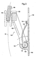
- the FIG. 2 shows an embodiment of the positioning means 118.
- the positioning means 118 have an arm-shaped positioning member 120, which in its in the FIG. 2 shown first position a stop on a stop region 122 of the Driver 104 forms. By this stop the mounting position of the driver 104 is set.
- the positioning element 120 is pivotally mounted on the door inner panel 102 about an axis 124.
- a bearing 126 is formed on the door inner panel 102.
- the pivotal position of the positioning member 120 in its first position is determined by a stop 128 formed between the positioning member 120 and the bearing 126.
- the positioning means 118 have an elastic member 130, such as a return spring, which serves to locate the positioning member 120 from its in the FIG. 2 to bring shown first position in a second position, and to hold there; in the second position, movement of the cam 104 along its travel 132 to open and close the mounted window glass 106 is released.
- the elastic member 130 is held by a snap hook 134.
- the mounting hole 136 in the door inner panel 102 is particularly advantageous for repair and maintenance work.
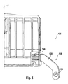
- FIG. 3 shows an embodiment of the positioning means 118 in perspective view when the positioning members 120 are in the first position.
- the FIG. 3 shows a central region of the door inner panel 102, on which the positioning means 118 are arranged.
- the resilient member 130 has a snap-in hook receiving slot 138 disposed on the door inner panel 102 so as to be accessible through the mounting hole 136.
- FIG. 3 shows the positioning means 118 when the snap hook 134 is not engaged in the receiving slot 138.
- the resilient member 130 holds the positioning means 118 in the second position. In this case, therefore, a restoring force acts on the positioning means 118.
- the stops 128 between the positioning means 118 and the bearing 126 are formed, whereby the pivot position is defined in the first position.
- the positioning members 120 At their end remote from the axle 124, the positioning members 120 each have a guide pin 140.
- the guide pins 140 are inserted into corresponding recesses of the driver 104 to fix it in the mounting position.
- the driver 104 has a pair of elastically spreadable jaws 142 with a hook-shaped or pin-shaped snap element 144 for latching into a corresponding disk hole 107 of the window pane 106 (cf. FIGS. 1 and 2 ).
- the positioning means 118 of the driver 104 is thus fixed in its mounting position. In this position, the window pane is pushed from above between the jaws 142, so that the snap element 144 is inserted into the pane hole 107 (cf. FIG. 1 ) engages.
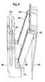
- the snap-action hook 134 is first latched into the receiving slot 138, whereby the positioning means 118 are brought into the second position. Thereafter, the positioning elements 120, for example, manually against the restoring force of the elastic member 130 in the first position, ie the mounting position, brought in the Fig. 4 is shown. In the first position, the stop 128 is formed.
- the driver 104 After mounting the window glass 106 and the cable 114 (see. Fig. 1 ), the driver 104 is moved by operating the window regulator assembly, so that the guide pins 140 are released; In the embodiment considered here, the driver 104 is moved downwards for this purpose, ie in the opening direction of the window pane 106. Due to the restoring force of the elastic element 130 (cf. Fig. 2 and 3 ), the positioning elements 120 pivot in their initial position, ie the second Position back, so that the travel 132 of the driver 104 is completely released.
- the positioning elements 120 are manually brought by the mounting hole 136 from the second to the first position.
- a motor vehicle mechanic can press with a screwdriver through the mounting hole 136 on one of the positioning members 120 so that the positioning members 120 are brought against the restoring force of the elastic member 130 in the first position.
- the driver 104 is moved by actuation of the window lift assembly so that it enters the positioning elements 120, that is, for example, in the guide pins 140, so that he in the Fig. 4 shown mounting position is brought.
- the connection between the driver 104 and the window glass 106 can be solved by the mounting hole 136 with a suitable tool and the window pane can be replaced.
- the windowpane 106 and the driver 104 can also be connected differently, e.g. by a screw connection, by an adhesive connection, clamping connection or the like.
- the FIG. 5 shows one side of the driver 104 and the positioning means 118.
- the positioning elements 120 are formed here as a pawl, which can engage in corresponding recesses 146 of the driver 104.
- the FIG. 5 shows one of the positioning members 120 in the first position, that is in the mounting position of the driver 104.
- the positioning member 120 is about the axis 124 on the door inner panel 102 (see. FIGS. 1 to 4 ) pivotally mounted. At least one further positioning element 120 is arranged on the other side of the driver 104.
- the positioning members 120 are configured to apply the force F upon depression of the window glass 106 between the jaws 142 (see FIG. FIG. 4 ) be able to record.
- the positioning member 120 slides out of the recess 146 by rotating clockwise about the axis 124.
- the positioning element 120 pivots about its axis 124 in a clockwise direction to its second position, outside the travel path of the driver 104.
- a spring may be arranged on the axis 124, which exerts a restoring force on the positioning element 120, to turn it to its second position clockwise.
- the positioning member 120 can also be mounted on the axle 125 opposite the axle 124, so that the positioning member 120 can project from top to bottom into the recess 146.
- the cam 104 is fixed in the mounting position by the positioning means 118, which has two of the symmetrically arranged positioning elements 120, without the positioning means 118 being adapted to receive the force F.
- the inclusion of the force F is rather by the attached to the driver 104 cable 114 (see. FIG. 1 ).
- the positioning element 120 is formed angularly and pivotally mounted about the formed on the driver 104 axis 124.
- the FIG. 6 shows the positioning member 120 in its first position, in which it determines the mounting position of the driver 104 relative to the door inner panel 102.
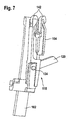
- FIG. 7 shows the positioning member 120 after it has been pivoted to its second position, in which it releases the movement of the driver 104.
- the positioning element 120 locks in this position, so that it can not unintentionally reach its first position during operation of the window lifter.
- FIG. 8 shows a further embodiment of the driver 104 and the positioning elements 120.
- the positioning elements 120 engagement elements (corresponding to the guide pins 140 of the embodiment of Figures 3 and 4 ), which serve for insertion into recesses 150 of the driver 104.
- the engagement elements are pivotable about the axes 124 with the locking lever 152 in the direction shown to the engagement elements of the shown first position to rotate in the second position shown in dashed lines.
- the axes are here formed on the door inner panel 102
- FIG. 9 shows a cross section of the door inner panel 102 in the region of the positioning means 118 of the embodiment of FIG. 8 ,
- the FIG. 9 shows the locking lever 152, after swinging into the second position. There, the locking lever 152 are locked by clamping elements 154.
- FIG. 10 shows a further embodiment of the positioning means 118 with a claw-shaped positioning element 120 for engagement in the recess 150 of the driver 104.
- Die FIG. 10 shows the positioning means in the first position; with dashed lines is the second position of the positioning means in the FIG. 10 shown.
- FIG. 11 shows a perspective view of the positioning member 120 in the embodiment of FIG. 10 .
- the positioning member 120 is formed claw-shaped and has, for example, approximately centrally a web 156, which receives the force F (see. FIGS. 1 and 5 ) when the positioning means 118 are in the first position.
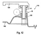
- FIG. 12 1 shows an embodiment of the positioning means 118 with a positioning member 120 slidably mounted approximately perpendicular to the door inner panel 102.
- the positioning member 120 By translating approximately perpendicularly to the door inner panel 102, the positioning member 120 can be brought into the first position A and the second position B ,
- the positioning element is formed in its upper region T-shaped to be inserted into a corresponding recess 150 of the driver 104.
Landscapes
- Engineering & Computer Science (AREA)
- Mechanical Engineering (AREA)
- Window Of Vehicle (AREA)
- Power-Operated Mechanisms For Wings (AREA)
Description
- Die Erfindung betrifft eine schienenlose Fensterheberanordnung, ein Türmodul mit einer Fensterheberanordnung und eine Kraftfahrzeugtür mit einer Fensterheberanordnung.
- Ausgangspunkt der vorliegenden Erfindung ist die aus der
DE 10 2004 017 645 A1 bekannte Fensterheberanordnung. Hieraus sind Mittel zum Positionieren und Fixieren des Mitnehmers zur Erleichterung der Montage einer Fensterscheibe bekannt. In der dort offenbarten Ausführungsform sind die Mittel zum Positionieren und Fixieren des Mitnehmers durch zwei Auflageblöcke gegeben, die einstückig an das Wandteil, das heißt die Tür-Innenplatte, eingeformt sind, und als untere Anschläge für den Mitnehmer dienen. - So genannte schienenlose Fensterheberanordnungen, der in der
DE 10 2004 017 645 A1 genannten Art, welche ohne eine Führungsschiene für den Mitnehmer auskommen, sind ebenfalls offenbart in derDE 102 55 461 A1 und der zum Anmeldezeitpunkt unveröffentlichtenDE 10 2005 037 324 . - Aus der
DE 195 05 624 C2 ist eine Vorrichtung zum Verbinden einer Fensterscheibe mit dem Mitnehmer eines Fensterhebers durch eine Schnappverbindung bekannt. - Aus der
DE 202 18 678 U1 ist eine Tür-Innenplatte bekannt, die als Träger für verschiedene Elemente eines Fensterhebers dient. Die Tür-Innenplatte hat eine Öffnung zur Montage des Fensterhebers von der Tür-Innenseite. - Dem gegenüber liegt der Erfindung die Aufgabe zu Grunde, eine verbesserte schienenlose Fensterheberanordnung, ein verbessertes Türmodul und eine verbesserte Kraftfahrzeugtür mit einer Fensterheberanordnung zu schaffen, um die Montage insbesondere einer Fensterscheibe mit großem Glassdrop zu vereinfachen.
- Die der Erfindung zu Grunde liegenden Aufgaben werden jeweils mit den Merkmalen der unabhängigen Patentansprüche gelöst. Bevorzugte Ausführungsformen der Erfindung sind in den abhängigen Patentansprüchen angegeben.
- Erfindungsgemäß wird eine schienenlose Fensterheberanordnung mit einem Mitnehmer für eine Fensterscheibe geschaffen. Die Fensterheberanordnung hat eine Tür-Innenplatte und Positionierungsmittel zur Positionierung des Mitnehmers in einer Montageposition zur Montage der Fensterscheibe.
- Die Positionierungsmittel können eine erste und eine zweite Stellung einnehmen. In der ersten Stellung definieren die Positionierungsmittel die Montageposition und in der zweiten Stellung geben die Positionierungsmittel eine Bewegung des Mitnehmers zum Öffnen oder Schließen der montierten Fensterscheibe frei. Die Positionierungsmittel sind zwischen der ersten und der zweiten Stellung schwenkbar. Außerdem haben die Positionierungsmittel ein elastisches Element zur Rückstellung in die zweite Stellung nach der Montage der Fensterscheibe. Alternativ oder zusätzlich können Klemmelemente zur Feststellung der Positionierungsmittel in der zweiten Stellung vorhanden sein. Hierdurch werden die Positionierungsmittel nach der Montage sicher in ihrer zweiten Stellung gehalten, so dass sie nicht die Bewegung des Mitnehmers beim Öffnen und Schließen der Fensterscheibe stören können.
- Die erfindungsgemäße Ausbildung der Positionierungsmittel hat den Vorteil, dass die Positionierungsmittel nicht gleichzeitig die maximale Öffnung der Fensterscheibe definieren, wie das bei der
DE 10 2004 017 645 A1 der Fall ist. Vielmehr können die Positionierungsmittel im Prinzip an einer beliebigen Stelle entlang des Verfahrwegs des Mitnehmers angeordnet sein. Dies ist insbesondere zur Montage einer Fensterheberanordnung vorteilhaft, bei der die Fensterscheibe ganz oder fast ganz in der Tür versenkt werden kann. Den Grad der Versenkbarkeit der Fensterscheibe in der Kraftfahrzeugtür bezeichnet man auch als "Glassdrop", wobei ein Glassdrop von 100 % bedeutet, dass die Fensterscheibe vollständig versenkbar ist. - Bei einer vollständig oder fast vollständig versenkbaren Fensterscheibe ragt die Fensterscheibe in ihrer vollständig geöffneten Position nicht oder fast nicht über die Türbrüstung hinaus, so dass eine Montage in der vollständig geöffneten Position schwierig ist. Die Erfindung ermöglicht dagegen die Anordnung der Positionierungsmittel so, dass die Fensterscheibe in der Montageposition über die Türbrüstung hinaus ragt, auch wenn es sich um einen Fensterheber mit einem großen Glassdrop, insbesondere 100 % Glassdrop handelt. In der Montageposition kann also der über die Türbrüstung hinaus ragende Abschnitt der Fensterscheibe bequem angefasst werden, was die Montage erheblich vereinfacht.
- In einer Ausführungsform der Erfindung sind die Positionierungsmittel in einem mittleren Bereich der Tür-Innenplatte angeordnet.
- In einer Ausführungsform der Erfindung sind die Positionierungsmittel an der Tür-Innenplatte beweglich gelagert und zur lösbaren Fixierung des Mitnehmers in der ersten Stellung ausgebildet. Beispielsweise können die Positionierungsmittel schwenkbar und / oder verschiebbar sein, so dass zwischen der ersten und der zweiten Stellung gewählt werden kann. Ferner können die Positionierungsmittel auch ganz oder teilweise von der Tür-Innenplatte lösbar sein, nachdem die Montage der Fensterscheibe erfolgt ist.
- Statt an der Tür-Innenplatte können die Positionierungsmittel auch an dem Mitnehmer beweglich, das heißt beispielsweise schwenkbar, verschiebbar oder zumindest teilweise lösbar, gelagert sein.
- In einer Ausführungsform der Erfindung sind die Positionierungsmittel zur Aufnahme der zur Ausbildung einer Rastverbindung zwischen dem Mitnehmer und der Fensterscheibe eingeleiteten Kraft ausgebildet. Wenn dies nicht der Fall ist, wird vor der Montage der Fensterscheibe zunächst ein Antriebselement an dem Mitnehmer angebracht, wie zum Beispiel das Zugseil, wenn der Fensterheber als Seilzug-Fensterheber ausgebildet ist. In diesem Fall kann das Zugseil die Kraft, mit der die Fensterscheibe zum Ausbilden der Rastverbindung in den Mitnehmer gedrückt wird, aufnehmen.
- In einem weiteren Aspekt betrifft die Erfindung ein Türmodul oder einer Kraftfahrzeugtür mit einer erfindungsgemäßen Fensterheberanordnung. Beispielsweise handelt es sich um eine Fensterheberanordnung ohne Führungsschiene für den Mitnehmer und einem relativ großen Glassdrop, von zum Beispiel nahe 100 %.
- Beschrieben sei außerdem ein Verfahren zur Montage einer Fensterheberanordnung. Zur Montage wird zunächst der Mitnehmer positioniert, indem die Positionierungsmittel in eine erste Stellung gebracht werden. Nach der Verbindung des Mitnehmers mit der Fensterscheibe, zum Beispiel durch Verrasten, werden die Positionierungsmittel in eine zweite Stellung gebracht, in der die Bewegung des Mitnehmers zum Öffnen oder Schließen der montierten Fensterscheibe freigegeben ist.
- Im weiteren werden Ausführungsformen der Erfindung mit Bezugnahme auf die Zeichnungen näher erläutert. Es zeigen:
- Figur 1
- eine schematische Darstellung einer Ausführungsform einer erfin- dungsgemäßen Kraftfahrzeug-Tür,
- Figur 2
- eine seitliche Schnittansicht einer Ausführungsform von erfindungsge- mäßen Positionierungsmitteln für einen Mitnehmer,
- Figur 3
- eine perspektivische Ansicht einer Ausführungsform erfindungsgemä- ßer Positionierungsmittel, die an einer Tür-Innenplatte schwenkbar ge- lagert sind,
- Figur 4
- eine perspektivische Ansicht der Ausführungsform der
Figur 3 , wenn sich die Positionierungsmittel in der ersten Stellung befinden, - Figur 5
- eine Ausführungsform erfindungsgemäßer Positionierungsmittel in der ersten Stellung
- Figur 6
- eine weitere Ausführungsform erfindungsgemäßer Positionierungsmittel in der ersten Stellung,
- Figur 7
- die Ausführungsform der
Figur 6 , wobei sich die Positionierungsmittel in der zweiten Stellung befinden, - Figur 8
- eine Schnittansicht einer Ausführungsform erfindungsgemäßer Positio- nierungsmittel mit einer Darstellung der ersten und zweiten Stellungen,
- Figur 9
- die Ausführungsform der
Figur 8 , mit einer Schnittansicht der Tür- Innenplatte, wenn sich die Positionierungsmittel in der zweiten Stellung befinden, - Figur 10
- eine weitere Ausführungsform erfindungsgemäßer Positionierungsmittel in einer Schnittdarstellung,
- Figur 11
- eine perspektivische Ansicht eines klauenförmigen Positionierungsele- ments der Ausführungsform gemäß
Figur 10 , - Figur 12
- eine Schnittansicht einer Ausführungsform erfindungsgemäßer Positio- nierungsmittel, wobei die Positionierungsmittel verschiebbar gelagert sind.
- Einander entsprechende Elemente der nachfolgend beschriebenen Ausführungsformen der Erfindung sind mit gleichen Bezugszeichen gekennzeichnet.
- Die
Figur 1 zeigt eine Kraftfahrzeug-Tür 100 mit einer Tür-Innenplatte 102. Die Tür-Innenplatte 102 dient als Träger zum Beispiel für verschiedene Antriebselemente einer Fensterheberanordnung. Gleichzeitig kann die Tür-Innenplatte als Trennwand zwischen einem Nassbereich und einem Trockenbereich der Kraftfahrzeug-Tür 100 dienen. - Die Fensterheberanordnung hat einen Mitnehmer 104 zur Verbindung mit einer Fensterscheibe 106. An der Tür-Innenplatte 102 und /oder an dem Mitnehmer 104 sind in der
Figur 1 nicht gezeigte Positionierungsmittel angeordnet. Die Positionierungsmittel haben eine erste Stellung zur Festlegung einer Montageposition zur Verbindung der Fensterscheibe 106 und des Mitnehmers 104 und eine zweite Stellung, in der eine Bewegung des Mitnehmers zum Öffnen oder Schließen der montierten Fensterscheibe entlang eines Verfahrwegs des Mitnehmers freigegeben ist. - Die
Figur 1 zeigt den Mitnehmer 104 in seiner Montageposition, die sich bei der hier betrachteten Ausführungsform der Fensterheberanordnung in etwa in der Mitte der Tür-Innenplatte 102 befindet. Nachdem der Mitnehmer 104 in der Montageposition positioniert worden ist, wird die Fensterscheibe 106 von oben aus ihrer gestrichelt gezeigten postition in ihre in ausgezogenen Linien gezeigte Montageposition gebracht. In der Montageposition wird die Fensterscheibe 106 mit dem Mitnehmer 104 verbunden, indem beispielsweise auf den oberen Rand 108 der Fensterscheibe 106 eine Kraft F ausgeübt wird, aufgrund derer der Mitnehmer 104 und die Fensterscheibe 106 eine Rastverbindung eingehen. Beispielsweise hat die Fensterscheibe 106 an ihrem unteren Rand ein Scheibenloch 107 zur Ausbildung der Rastverbindung mit dem Mitnehmer 104. - Besonders vorteilhaft ist bei der in der
Figur 1 gezeigten Ausführungsform, dass die Fensterscheibe 106 in ihrer Montageposition mit ihrem Bereich 110 über die Türbrüstung 112 der Kraftfahrzeug-Tür 100 herausragt. Dies ermöglicht eine bequeme Montage der Fensterscheibe 106 und insbesondere die Einleitung der Kraft F. - Vor oder nach der Verbindung der Fensterscheibe 106 und des Mitnehmers 104 wird der Mitnehmer 104 mit einem Antriebselement der Fensterheberanordnung verbunden. Bei dem Antriebselement handelt es sich beispielsweise um ein Seil 114, welches über eine Antriebstrommel 116 der Fensterheberanordnung geführt ist. Die zur Ausbildung der Rast- oder Schnappverbindung zwischen dem Mitnehmer 104 und der Fensterscheibe 106 ausgeübte Kraft F wird durch die Positionierungsmittel und / oder durch das Seil 114 aufgenommen.
- Beispielsweise handelt es sich bei der Fensterheberanordnung der
Figur 1 um eine Ausführungsform mit einem relativ großen Glassdrop, beispielsweise einem Glassdrop von 100 % oder nahe 100 %. Dies bedeutet, dass die Fensterscheibe 106 nach ihrer Montage durch Betätigung der Fensterheberanordnung vollständig oder fast vollständig unter die Türbrüstung 112 verfahren werden kann, so dass auch der Bereich 110 der Fensterscheibe 106 unterhalb der Türbrüstung 112 verschwindet. - Die
Figur 2 zeigt eine Ausführungsform der Positionierungsmittel 118. Die Positionierungsmittel 118 haben ein armförmiges Positionierungselement 120, das in seiner in derFigur 2 gezeigten ersten Stellung einem Anschlag an einem Anschlagsbereich 122 des Mitnehmers 104 bildet. Durch diesen Anschlag wird die Montageposition des Mitnehmers 104 festgelegt. - Das Positionierungselement 120 ist an der Tür-Innenplatte 102 um eine Achse 124 schwenkbar gelagert. Hierzu ist an der Tür-Innenplatte 102 ein Lager 126 ausgebildet. Die Schwenkposition des Positionierungselements 120 in seiner ersten Stellung wird durch einen zwischen dem Positionierungselement 120 und dem Lager 126 gebildeten Anschlag 128 festgelegt.
- Die Positionierungsmittel 118 haben ein elastisches Element 130, wie zum Beispiel eine Rückstellfeder, welche dazu dient, das Positionierungselement 120 aus seiner in der
Figur 2 gezeigten ersten Stellung in eine zweite Stellung zu bringen, und dort zu halten; in der zweiten Stellung wird eine Bewegung des Mitnehmers 104 entlang seines Verfahrweges 132 zum Öffnen und Schließen der montierten Fensterscheibe 106 freigegeben. Das elastische Elements 130 wird von einem Schnapphaken 134 gehalten. Das Montageloch 136 in der Tür-Innenptatte 102 ist insbesondere für Reparatur- und Wartungsarbeiten vorteilhaft. - Die
Figur 3 zeigt eine Ausführungsform der Positionierungsmittel 118 in perspektivischer Ansicht, wenn sich die Positionierungselemente 120 in der ersten Stellung befinden. DieFigur 3 zeigt einen mittleren Bereich der Tür-Innenplatte 102, an dem die Positionierungsmittel 118 angeordnet sind. - In der hier betrachteten Ausführungsform hat das elastische Element 130 einen Aufnahmeschlitz 138 für einen Schnapphaken 134, der an der Tür-Innenplatte 102 so angeordnet ist, dass er durch das Montageloch 136 zugänglich ist.
- Die
Figur 3 zeigt die Positionierungsmittel 118, wenn der Schnapphaken 134 nicht in dem Aufnahmeschlitz 138 eingerastet ist. Nachdem der Schnapphaken 124 in den Aufnahmeschlitz 138 eingerastet ist, hält das elastische Element 130 die Positionierungsmittel 118 in der zweiten Stellung. In diesem Fall wirkt also eine Rückstellkraft auf die Positionierungsmittel 118. - In der in der
Figur 3 gezeigten ersten Stellung der Positionierungsmittel 118 werden die Anschläge 128 zwischen den Positionierungsmitteln 118 und dem Lager 126 gebildet, wodurch die Schwenkposition in der ersten Stellung definiert ist. An ihrem zu der Achse 124 entfernten Ende haben die Positionierungselemente 120 jeweils einen Führungsstift 140. - Wie in der
Figur 4 dargestellt, werden die Führungsstifte 140 in entsprechende Ausnehmungen des Mitnehmers 104 eingeführt, um diesen in der Montageposition zu fixieren. Der Mitnehmer 104 hat in dieser Ausführungsform ein Paar elastisch spreizbarer Backen 142 mit einem haken- oder stiftförmigen Schnappelement 144 zum Einrasten in ein entsprechendes Scheibenloch 107 der Fensterscheibe 106 (vgl.Figuren 1 und2 ). - Durch die Positionierungsmittel 118 wird der Mitnehmer 104 also in seiner Montageposition fixiert. In dieser Position wird die Fensterscheibe von oben zwischen die Backen 142 geschoben, so dass das Schnappelement 144 in das Scheibenloch 107 (vgl.
Figur 1 ) einrastet. - Zur Montage der Fensterscheibe 106 (vgl.
Fig. 1 ) wird zunächst der Schnapphacken 134 in den Aufnahmeschlitz 138 eingerastet, wodurch die Positionierungsmittel 118 in die zweite Stellung gebracht werden. Danach werden die Positionierungselemente 120 z.B. manuell entgegen der Rückstellkraft des elastischen Elements 130 in die erste Stellung, d.h. die Montageposition, gebracht, die in derFig. 4 gezeigt ist. In der ersten Stellung wird der Anschlag 128 gebildet. - Nach der Montage der Fensterscheibe 106 und des Seils 114 (vgl.
Fig. 1 ), wird der Mitnehmer 104 durch Betätigung der Fensterheberanordnung verfahren, so dass die Führungsstifte 140 freigegeben werden; in der hier betrachteten Ausführungsform wird der Mitnehmer 104 hierzu nach unten verfahren, d.h. in Öffnungsrichtung der Fensterscheibe 106. Aufgrund der Rückstellkraft des elastischen Elements 130 (vgl.Fig. 2 und3 ) schwenken die Positionierungselemente 120 in ihre Ausgangsstellung, d.h. die zweite Stellung zurück, so dass der Verfahrweg 132 des Mitnehmers 104 vollständig freigegeben wird. - Zum Austausch der Fensterscheibe werden die Positionierungselemente 120 manuell durch das Montageloch 136 aus der zweiten in die erste Stellung gebracht. Beispielsweise kann ein Kraftfahrzeugmechaniker mit einem Schraubenzieher durch das Montageloch 136 hindurch auf eines der Positionierungselemente 120 drücken, so das die Positionierungselemente 120 entgegen der Rückstellkraft des elastischen Elements 130 in die erste Position gebracht werden. Danach wird durch Betätigung der Fensterheberanordnung der Mitnehmer 104 so verfahren, das er in die Positionierungselemente 120, also z.B. in die Führungsstifte 140, einfährt, so dass er die in der
Fig. 4 gezeigt Montageposition gebracht wird. In dieser Stellung kann die Verbindung zwischen dem Mitnehmer 104 und der Fensterscheibe 106 durch das Montageloch 136 mit einem geeigneten Werkzeug gelöst und die Fensterscheibe ausgetauscht werden. - Statt durch eine Schnappverbindung können die Fensterscheibe 106 und der Mitnehmer 104 auch anders verbunden werden, z.B. durch eine Verschraubung, durch eine Klebeverbindung, Klemmverbindung oder dergleichen.
- Die
Figur 5 zeigt eine Seite des Mitnehmers 104 und der Positionierungsmittel 118. Die Positionierungselemente 120 sind hier als Sperrhaken ausgebildet, die in entsprechende Ausnehmungen 146 des Mitnehmers 104 eingreifen können. DieFigur 5 zeigt eines der Positionierungselemente 120 in der ersten Stellung, das heißt in der Montageposition des Mitnehmers 104. Das Positionierungselement 120 ist um die Achse 124 an der Tür-Innenplatte 102 (vgl.Figuren 1 bis 4 ) schwenkbar gelagert. Zumindest ein weiteres Positionierungselement 120 ist an der anderen Seite des Mitnehmers 104 angeordnet. - In der Ausführungsform der
Figur 5 sind die Positionierungselemente 120 so ausgebildet, dass sie die Kraft F beim Eindrücken der Fensterscheibe 106 zwischen die Bakken 142 (vgl.Figur 4 ) aufnehmen können. Wenn nach der Montage der Fensterscheibe der Mitnehmer 104 nach oben verfahren wird, gleitet das Positionierungselement 120 aus der Ausnehmung 146, indem es sich im Uhrzeigersinn um die Achse 124 dreht. Nachdem das Positionierungselement 120 den Mitnehmer 104 vollständig freigegeben hat, schwenkt es um seine Achse 124 im Uhrzeigersinn in seine zweite Stellung, außerhalb des Verfahrwegs des Mitnehmers 104. Hierzu kann auf der Achse 124 eine Feder angeordnet sein, die eine Rückstellkraft auf das Positionierungselement 120 ausübt, um es in seine zweite Stellung im Uhrzeigersinn zu drehen. - Alternativ kann das Positionierungselement 120 auch auf der Achse 125 montiert werden, die der Achse 124 gegenüberliegt, so dass das Positionierungselement 120 von oben nach unten in die Ausnehmung 146 ragen kann. In diesem Fall wird der Mitnehmer 104 durch die Positionierungsmittel 118, die zwei der symmetrisch angeordneten Positionierungselemente 120 aufweist, in der Montageposition fixiert, ohne dass die Positionierungsmittel 118 dazu ausgebildet sind, die Kraft F aufzunehmen. Die Aufnahme der Kraft F erfolgt vielmehr durch das an den Mitnehmer 104 befestigte Seil 114 (vgl.
Figur 1 ). - In der Ausführungsform der
Figur 6 ist das Positionierungselement 120 winkelförmig ausgebildet und um die an dem Mitnehmer 104 ausgebildete Achse 124 schwenkbar gelagert. DieFigur 6 zeigt das Positionierungselement 120 in seiner ersten Stellung, in der es die Montageposition des Mitnehmers 104 relativ zu der Tür-Innenplatte 102 festlegt. - Die
Figur 7 zeigt das Positionierungselement 120, nachdem es in seine zweite Stellung geschwenkt worden ist, in der es die Bewegung des Mitnehmers 104 freigibt. Beispielsweise verrastet das Positionierungselement 120 in dieser Stellung, so dass es beim Betrieb des Fensterhebers nicht ungewollt in seine erste Stellung gelangen kann. - Die
Figur 8 zeigt eine weitere Ausführungsform des Mitnehmers 104 und der Positionierungselemente 120. In der hier betrachteten Ausführungsform haben die Positionierungselemente 120 Eingriffselemente (entsprechend den Führungsstiften 140 der Ausführungsform derFiguren 3 und4 ), die zur Einführung in Ausnehmungen 150 des Mitnehmers 104 dienen. Die Eingriffselemente sind um die Achsen 124 mit dem Sperrhebel 152 in dem gezeigten Richtungssinn schwenkbar, um die Eingriffselemente aus der gezeigten ersten Stellung in die gestrichelt dargestellte zweite Stellung zu drehen. Die Achsen sind hier an der Tür-Innenplatte 102 ausgebildet - Die
Figur 9 zeigt einen Querschnitt der Tür-Innenplatte 102 im Bereich der Positionierungsmittel 118 der Ausführungsform derFigur 8 . DieFigur 9 zeigt die Sperrhebel 152, nach dem Einschwenken in die zweite Stellung. Dort werden die Sperrhebel 152 durch Klemmelemente 154 arretiert. - Die
Figur 10 zeigt eine weitere Ausführungsform der Positionierungsmittel 118 mit einem klauenförmigen Positionierungselement 120 zum Eingriff in die Ausnehmung 150 des Mitnehmers 104. DieFigur 10 zeigt die Positionierungsmittel in der ersten Stellung; mit gestrichelten Linien ist die zweite Stellung der Positionierungsmittel in derFigur 10 dargestellt. - Die
Figur 11 zeigt eine perspektivische Ansicht des Positionierungselements 120 in der Ausführungsform derFigur 10 . Das Positionierungselement 120 ist klauenförmig ausgebildet und hat beispielsweise in etwa mittig einen Steg 156, der zur Aufnahme der Kraft F (vgl.Figuren 1 und5 ) dient, wenn sich die Positionierungsmittel 118 in der ersten Stellung befinden. - Die
Figur 12 zeigt eine Ausführungsform der Positionierungsmittel 118 mit einem in etwa senkrecht zu der Tür-Innenplatte 102 verschiebbar gelagertem Positionierungselement 120. Durch-Verschiebung in etwa senkrecht zu der Tür-Innenplatte 102 kann das Positionierungselement 120 in die erste Stellung A und die zweite Stellung B gebracht werden. In dieser Ausführungsform ist das Positionierungselement in seinem oberen Bereich T-förmig ausgebildet, um in eine entsprechende Ausnehmung 150 des Mitnehmers 104 eingeführt zu werden. -
- 100
- Kraftfahrzeug-Tür
- 102
- Tür-Innenplatte
- 104
- Mitnehmer
- 106
- Fensterscheibe
- 107
- Scheibenloch
- 108
- Rand
- 110
- Bereich
- 112
- Türbrüstung
- 114
- Seil
- 116
- Antriebstrommel
- 118
- Positionierungsmittel
- 120
- Positionierungselement
- 122
- Anschlagsbereich
- 124
- Achse
- 125
- Achse
- 126
- Lager
- 128
- Anschlag
- 130
- elastisches Element
- 132
- Verfahrweg
- 134
- Schnapphaken
- 136
- Montageloch
- 138
- Aufnahmeschlitz
- 140
- Führungsstift
- 142
- Backen
- 144
- Schnappelement
- 146
- Ausnehmung
- 150
- Ausnehmung
- 152
- Sperrhebel
- 154
- Klemmelement
- 156
- Steg
Claims (14)
- Schienenlose Fensterheberanordnung mit- einem Mitnehmer (104) für eine Fensterscheibe (106),- einer Tür-Innenplatte (102),- Positionierungsmitteln (118, 120, 122, 124, 125, 126, 128, 130, 134, 136, 138, 140, 146, 148, 152, 154, 156) zur Positionierung des Mitnehmers (104) relativ zu der Tür-Innenplatte (102) in einer Montageposition zur Montage der Fensterscheibe (106), wobei die Positionierungsmittel (118) eine erste und eine zweite Stellung einnehmen können, wobei die Positionierungsmittel (118) in der ersten Stellung die Montageposition definieren, und wobei die Positionierungsmittel (118) in der zweiten Stellung eine Bewegung des Mitnehmers (104) zum Öffnen und Schließen der montierten Fensterscheibe (106) freigeben,dadurch gekennzeichnet, dass
die Positionierungsmittel (118) zwischen der ersten und der zweiten Stellung schwenkbar sind und die Positionierungsmittel (118) ein elastisches Element (130) zur Rückstellung in die zweite Stellung nach der Montage der Fensterscheibe (106) aufweisen. - Schienenlose Fensterheberanordnung nach Anspruch 1, dadurch gekennzeichnet, dass die Positionierungsmittel (118) so angeordnet sind, dass die Fensterscheibe (106) in der Montageposition über eine Türbrüstung (112) hinaus ragt.
- Schienenlose Fensterheberanordnung nach Anspruch 1 oder 2, dadurch gekennzeichnet, dass der Mitnehmer (104) zur Ausbildung einer Rastverbindung (107,144) mit der Fensterscheibe (106) in der Montageposition ausgebildet ist.
- Schienenlose Fensterheberanordnung nach Anspruch 1, 2 oder 3, dadurch gekennzeichnet, dass die Positionierungsmittel (118) in einem mittleren Bereich der Tür-Innenplatte (102) angeordnet sind.
- Schienenlose Fensterheberanordnung nach einem der vorhergehenden Ansprüche, dadurch gekennzeichnet, dass die Positionierungsmittel (118) an der Tür-Innenplatte (102) beweglich gelagert und zur lösbaren Fixierung des Mitnehmers (104) in der ersten Stellung ausgebildet sind.
- Schienenlose Fensterheberanordnung nach einem der vorhergehenden Ansprüche 1 bis 4, dadurch gekennzeichnet, dass die Positionierungsmittel (118) an dem Mitnehmer (104) beweglich gelagert und zur lösbaren Fixierung des Mitnehmers (104) in der ersten Stellung ausgebildet sind.
- Schienenlose Fensterheberanordnung nach einem der vorhergehenden Ansprüche, dadurch gekennzeichnet, dass die Positionierungsmittel (118) ein Eingriffselement (120; 140) für die lösbare Fixierung aufweisen.
- Schienenlose Fensterheberanordnung nach einem der vorhergehenden Ansprüche, dadurch gekennzeichnet, dass die Positionierungsmittel (118) zwischen der ersten und der zweiten Stellung verschiebbar sind.
- Schienenlose Fensterheberanordnung nach einem der vorhergehenden Ansprüche, dadurch gekennzeichnet, dass die Positionierungsmittel (118) ganz oder teilweise von der Tür-Innenplatte (102) oder dem Mitnehmer (104) lösbar sind, um die Bewegung des Mitnehmers (104) zum Öffnen oder Schließen der montierten Fensterscheibe (106) freizugeben.
- Schienenlose Fensterheberanordnung nach einem der vorhergehenden Ansprüche, dadurch gekennzeichnet, dass die Fensterheberanordnung eine oder mehrere Klemmelemente (154) zur Feststellung der Positionierungsmittel (118) in der zweiten Stellung aufweist.
- Schienenlose Fensterheberanordnung nach einem der vorhergehenden Ansprüche, dadurch gekennzeichnet, dass die Positionierungsmittel (118) zur Aufnahme einer zur Ausbildung der Rastverbindung ausgeübten Kraft ausgebildet sind.
- Schienenlose Fensterheberanordnung nach einem der vorhergehenden Ansprüche, dadurch gekennzeichnet, dass die Fensterheberanordnung einen Glasdrop von nahe 100% aufweist.
- Türmodul mit einer Fensterheberanordnung nach einem der vorhergehenden Ansprüche.
- Kraftfahrzeugtür mit einer Fensterheberanordnung nach einem der vorhergehenden Ansprüche 1 bis 12.
Applications Claiming Priority (2)
| Application Number | Priority Date | Filing Date | Title |
|---|---|---|---|
| DE102005061009A DE102005061009B3 (de) | 2005-12-19 | 2005-12-19 | Fensterheberanordnung, Türmodul, Kraftfahrzeugtür und Verfahren zur Montage einer Fensterheberanordnung |
| PCT/EP2006/069784 WO2007071629A1 (de) | 2005-12-19 | 2006-12-15 | Fensterheberanordnung, türmodul, kraftfahrzeugtür und verfahren zur montage einer fensterheberanordnung |
Publications (2)
| Publication Number | Publication Date |
|---|---|
| EP1966459A1 EP1966459A1 (de) | 2008-09-10 |
| EP1966459B1 true EP1966459B1 (de) | 2009-11-11 |
Family
ID=37807974
Family Applications (1)
| Application Number | Title | Priority Date | Filing Date |
|---|---|---|---|
| EP06830669A Not-in-force EP1966459B1 (de) | 2005-12-19 | 2006-12-15 | Schienenlose fensterheberanordnung, türmodul und kraftfahrzeugtür |
Country Status (6)
| Country | Link |
|---|---|
| US (1) | US8240086B2 (de) |
| EP (1) | EP1966459B1 (de) |
| KR (1) | KR101341337B1 (de) |
| AT (1) | ATE448380T1 (de) |
| DE (2) | DE102005061009B3 (de) |
| WO (1) | WO2007071629A1 (de) |
Cited By (1)
| Publication number | Priority date | Publication date | Assignee | Title |
|---|---|---|---|---|
| US8544209B2 (en) | 2008-12-01 | 2013-10-01 | Brose Fahrzeugteile Gmbh & Co. Kg, Hallstadt | Window lifter assembly |
Families Citing this family (15)
| Publication number | Priority date | Publication date | Assignee | Title |
|---|---|---|---|---|
| US8132368B2 (en) * | 2005-12-19 | 2012-03-13 | Faurecia Innenraum Systeme Gmbh | Window lift apparatus, door module, motor vehicle door and method for installation of a window lift apparatus |
| DE102006030238B4 (de) | 2006-06-30 | 2012-10-18 | Faurecia Innenraum Systeme Gmbh | Mitnehmer für eine Fensterheberanordnung |
| FR2920402B1 (fr) * | 2007-08-29 | 2010-02-26 | Peugeot Citroen Automobiles Sa | Dispositif d'aide au montage d'une vitre dans un caisson d'une porte de vehicule automobile. |
| DE202007018213U1 (de) | 2007-12-28 | 2009-05-07 | Brose Fahrzeugteile Gmbh & Co. Kommanditgesellschaft, Hallstadt | Schienenloser Seil-Fensterheber |
| US20100088964A1 (en) * | 2008-10-10 | 2010-04-15 | Gm Global Technology Operations, Inc. | Snap-in glass retention for a vehicle door |
| DE102008044175B4 (de) | 2008-11-28 | 2010-12-23 | Faurecia Innenraum Systeme Gmbh | Montagevorrichtung zur Montage einer Fensterscheibe an einen Mitnehmer eines Fensterhebers |
| DE202008017217U1 (de) | 2008-12-19 | 2010-04-29 | Brose Fahrzeugteile Gmbh & Co. Kommanditgesellschaft, Hallstadt | Fensterheberbaugruppe mit Positionierungselement für eine Fensterscheibe |
| DE102008064566A1 (de) * | 2008-12-19 | 2010-06-24 | Brose Fahrzeugteile Gmbh & Co. Kommanditgesellschaft, Hallstadt | Positionierungswerkzeug und Montageverfahren für eine Fensterheberbaugruppe |
| DE102011054192B4 (de) | 2011-10-05 | 2019-01-03 | Küster Holding GmbH | Fensterheber für ein Kraftfahrzeug, mit einem durch einen Seilzug betätigbaren Mitnehmer |
| DE102011054212A1 (de) | 2011-10-05 | 2013-04-11 | Küster Holding GmbH | Verfahren zum Festlegen einer Fensterscheibe an einem Mitnehmer eines Fensterhebers und Fensterheber |
| US9790728B2 (en) * | 2015-07-17 | 2017-10-17 | Hi-Lex Controls, Inc. | Single-rail window regulator assembly |
| US9822571B2 (en) * | 2016-02-19 | 2017-11-21 | Hi-Lex Controls Inc. | Window clamp and assembly for window regulator |
| EP3241697B1 (de) * | 2016-05-02 | 2018-08-01 | Magna Steyr Fahrzeugtechnik AG & Co KG | Fensterheber |
| DE102021211902A1 (de) * | 2021-10-21 | 2023-04-27 | Brose Fahrzeugteile Se & Co. Kommanditgesellschaft, Bamberg | Befestigungsvorrichtung für einen Fensterheber sowie Fensterheber |
| WO2023078533A1 (fr) * | 2021-11-02 | 2023-05-11 | Advanced Comfort Systems France Sas - Acs France | Dispositif vitré pour porte de véhicule à panneau mobile affleurant et porte correspondante |
Family Cites Families (20)
| Publication number | Priority date | Publication date | Assignee | Title |
|---|---|---|---|---|
| JP2829947B2 (ja) * | 1987-03-24 | 1998-12-02 | 日産自動車株式会社 | 自動車のドア組立方法 |
| FR2637001B1 (de) * | 1988-09-29 | 1995-06-30 | Rockwell Cim | |
| DE4426670A1 (de) * | 1994-07-28 | 1996-02-01 | Brose Fahrzeugteile | Vorrichtung zum Verbinden einer Fensterscheibe mit einem Fensterheber |
| DE19505624C2 (de) * | 1995-02-18 | 2003-06-12 | Brose Fahrzeugteile | Vorrichtung zum Verbinden einer Fensterscheibe mit einem Fensterheber |
| DE19653046A1 (de) * | 1996-12-19 | 1998-06-25 | Brose Fahrzeugteile | Vorrichtung zur Befestigung einer verschiebbaren Fensterscheibe eines Kraftfahrzeugs an der Führungsvorrichtung eines Fensterhebers |
| DE19819910C1 (de) * | 1998-05-05 | 1999-06-17 | Brose Fahrzeugteile | Mitnehmer zur Anbindung einer Fensterscheibe an einen Fensterheber |
| FR2781006B1 (fr) | 1998-07-08 | 2000-10-06 | Meritor Light Vehicle Sys Ltd | Dispositif de leve-vitre de porte de vehicule automobile |
| US6330764B1 (en) * | 1999-11-19 | 2001-12-18 | Larry G. Klosterman | Door window mounting and regulator assembly and method for assembly |
| JP3756750B2 (ja) * | 2000-10-31 | 2006-03-15 | 株式会社大井製作所 | ウインドレギュレータのウインドパネル支持構造 |
| FR2830894B1 (fr) * | 2001-10-16 | 2004-04-16 | Meritor Light Vehicle Sys Ltd | Leve-vitre avec blocage de curseur et procede d'assemblage correspondant |
| DE10255461B4 (de) | 2002-11-25 | 2007-05-16 | Faurecia Innenraum Sys Gmbh | Fensterheberanordnung sowie Kraftfahrzeugtür |
| DE20218678U1 (de) * | 2002-12-03 | 2003-02-13 | Brose Fahrzeugteile GmbH & Co. Kommanditgesellschaft, Coburg, 96450 Coburg | Kraftfahrzeugtür und Trägerplatte einer Kraftfahrzeugtür |
| ITTO20030172A1 (it) * | 2003-03-07 | 2004-09-08 | Andrea Napoli | Alzacristallo per autoveicoli. |
| ES1055444Y (es) * | 2003-08-26 | 2004-03-01 | Castellon Melchor Daumal | Pinza de sujecion para cristales en elevalunas de automoviles. |
| US7409797B2 (en) * | 2003-10-02 | 2008-08-12 | Arvinmeritor Technology, Llc | Self-fastening glass attachment clip |
| DE102004017645A1 (de) * | 2004-04-02 | 2005-11-03 | Faurecia Innenraum Systeme Gmbh | Fensterheberanordnung und Verfahren zur Montage einer Fensterscheibe |
| US20070006533A1 (en) * | 2005-07-11 | 2007-01-11 | Faurecia Interior Systems U.S.A., Inc. | Vehicle window lift plate |
| US20070151161A1 (en) * | 2006-01-03 | 2007-07-05 | Arvinmeritor Technology, Llc | Cursor with dampener |
| US20080098657A1 (en) * | 2006-10-26 | 2008-05-01 | Faurecia Interior Systems U.S.A., Inc. | Mid-Travel Position Installation of Window Glass |
| US7721487B2 (en) * | 2007-08-10 | 2010-05-25 | Gm Global Technology Operations, Inc. | Glass attachment for movable vehicle window |
-
2005
- 2005-12-19 DE DE102005061009A patent/DE102005061009B3/de not_active Expired - Fee Related
-
2006
- 2006-12-15 WO PCT/EP2006/069784 patent/WO2007071629A1/de not_active Ceased
- 2006-12-15 EP EP06830669A patent/EP1966459B1/de not_active Not-in-force
- 2006-12-15 AT AT06830669T patent/ATE448380T1/de not_active IP Right Cessation
- 2006-12-15 DE DE502006005375T patent/DE502006005375D1/de active Active
- 2006-12-15 US US12/093,609 patent/US8240086B2/en not_active Expired - Fee Related
- 2006-12-15 KR KR1020087013428A patent/KR101341337B1/ko not_active Expired - Fee Related
Cited By (1)
| Publication number | Priority date | Publication date | Assignee | Title |
|---|---|---|---|---|
| US8544209B2 (en) | 2008-12-01 | 2013-10-01 | Brose Fahrzeugteile Gmbh & Co. Kg, Hallstadt | Window lifter assembly |
Also Published As
| Publication number | Publication date |
|---|---|
| ATE448380T1 (de) | 2009-11-15 |
| DE502006005375D1 (de) | 2009-12-24 |
| DE102005061009B3 (de) | 2007-08-23 |
| KR20080080297A (ko) | 2008-09-03 |
| EP1966459A1 (de) | 2008-09-10 |
| KR101341337B1 (ko) | 2013-12-13 |
| WO2007071629A1 (de) | 2007-06-28 |
| US20080289256A1 (en) | 2008-11-27 |
| US8240086B2 (en) | 2012-08-14 |
Similar Documents
| Publication | Publication Date | Title |
|---|---|---|
| EP1966459B1 (de) | Schienenlose fensterheberanordnung, türmodul und kraftfahrzeugtür | |
| EP3408484B1 (de) | Fensterheberbaugruppe mit mehrteiligem scheibenführungselement für ein flächenbündiges scheibenkonzept und montageverfahren | |
| EP1835113A2 (de) | Einstellbarer Fensterheber | |
| DE102015201587A1 (de) | Antriebssystem für einen beweglichen Dachteil eines Dachmoduls eines Kraftfahrzeugs | |
| EP3122976B1 (de) | Mitnehmer für eine verschiebbare fensterscheibe, fensterscheibenanordnung | |
| EP2455247B1 (de) | Schiebedachsysteme | |
| EP1977066A1 (de) | Mitnehmer für eine fensterheberanordnung | |
| DE3725727C1 (de) | ||
| EP2046593B1 (de) | Türmodul mit fensterhebereinrichtung | |
| DE102009033939B4 (de) | Wohndachfenster sowie Verfahren zum Befestigen eines Abdeckblechs | |
| DE102005012419B4 (de) | Lagerbügel eines Außengriffes einer Fahrzeugtür für Kraftfahrzeuge | |
| DE19838431C2 (de) | Gehäuse für ein elektrisches Gerät | |
| DE10238623A1 (de) | Kraftfahrzeug-Türschloß | |
| EP3860400B1 (de) | Befestigungsvorrichtung für eine blende eines schubkastens an einer zarge | |
| EP3592929B1 (de) | Montageeinheit und verfahren zur montage einer führungsschiene an einem oberboden oder boden eines möbels | |
| DE102021006594A1 (de) | Rolloanordnung mit Zugspriegel und Antriebskabeln | |
| EP1905631A1 (de) | Sicherheits-Bremsvorrichtung eines Schiebedachdeckels | |
| EP3235984B1 (de) | Beschlag für ein fenster, verfahren zum herstellen des beschlags sowie entsprechendes fenster | |
| EP1912812B1 (de) | Rollosystem mit gebremstem gleiter | |
| EP3870788A1 (de) | Fensterhebersystem und kraftfahrzeugtür | |
| DE102011085741A1 (de) | Bahngesteuerte Verstellvorrichtung für eine Fensterscheibe eines Kraftfahrzeugs | |
| DE102008044175B4 (de) | Montagevorrichtung zur Montage einer Fensterscheibe an einen Mitnehmer eines Fensterhebers | |
| DE202008014752U1 (de) | Fensterheberbaugruppe | |
| DE202017106967U1 (de) | Eine Scharnieranordnung mit bogenförmigen Führungsmitteln und einer Bremseinrichtung, sowie ein Dachfenster mit einer derartigen Scharnieranordnung | |
| DE4134065C1 (en) | Slide support for car sun roof - has slide guideway with slots along both long sides, coacting with associated guide rails |
Legal Events
| Date | Code | Title | Description |
|---|---|---|---|
| PUAI | Public reference made under article 153(3) epc to a published international application that has entered the european phase |
Free format text: ORIGINAL CODE: 0009012 |
|
| 17P | Request for examination filed |
Effective date: 20080721 |
|
| AK | Designated contracting states |
Kind code of ref document: A1 Designated state(s): AT BE BG CH CY CZ DE DK EE ES FI FR GB GR HU IE IS IT LI LT LU LV MC NL PL PT RO SE SI SK TR |
|
| 17Q | First examination report despatched |
Effective date: 20090216 |
|
| GRAP | Despatch of communication of intention to grant a patent |
Free format text: ORIGINAL CODE: EPIDOSNIGR1 |
|
| RTI1 | Title (correction) |
Free format text: RAILLESS WINDOW WINDER ARRANGEMENT, DOOR MODULE AND MOTOR VEHICLE DOOR |
|
| DAX | Request for extension of the european patent (deleted) | ||
| GRAS | Grant fee paid |
Free format text: ORIGINAL CODE: EPIDOSNIGR3 |
|
| GRAA | (expected) grant |
Free format text: ORIGINAL CODE: 0009210 |
|
| AK | Designated contracting states |
Kind code of ref document: B1 Designated state(s): AT BE BG CH CY CZ DE DK EE ES FI FR GB GR HU IE IS IT LI LT LU LV MC NL PL PT RO SE SI SK TR |
|
| REG | Reference to a national code |
Ref country code: GB Ref legal event code: FG4D Free format text: NOT ENGLISH |
|
| REG | Reference to a national code |
Ref country code: CH Ref legal event code: EP |
|
| REG | Reference to a national code |
Ref country code: IE Ref legal event code: FG4D |
|
| REF | Corresponds to: |
Ref document number: 502006005375 Country of ref document: DE Date of ref document: 20091224 Kind code of ref document: P |
|
| NLV1 | Nl: lapsed or annulled due to failure to fulfill the requirements of art. 29p and 29m of the patents act | ||
| LTIE | Lt: invalidation of european patent or patent extension |
Effective date: 20091111 |
|
| PG25 | Lapsed in a contracting state [announced via postgrant information from national office to epo] |
Ref country code: FI Free format text: LAPSE BECAUSE OF FAILURE TO SUBMIT A TRANSLATION OF THE DESCRIPTION OR TO PAY THE FEE WITHIN THE PRESCRIBED TIME-LIMIT Effective date: 20091111 Ref country code: IS Free format text: LAPSE BECAUSE OF FAILURE TO SUBMIT A TRANSLATION OF THE DESCRIPTION OR TO PAY THE FEE WITHIN THE PRESCRIBED TIME-LIMIT Effective date: 20100311 Ref country code: LT Free format text: LAPSE BECAUSE OF FAILURE TO SUBMIT A TRANSLATION OF THE DESCRIPTION OR TO PAY THE FEE WITHIN THE PRESCRIBED TIME-LIMIT Effective date: 20091111 Ref country code: PT Free format text: LAPSE BECAUSE OF FAILURE TO SUBMIT A TRANSLATION OF THE DESCRIPTION OR TO PAY THE FEE WITHIN THE PRESCRIBED TIME-LIMIT Effective date: 20100311 Ref country code: SE Free format text: LAPSE BECAUSE OF FAILURE TO SUBMIT A TRANSLATION OF THE DESCRIPTION OR TO PAY THE FEE WITHIN THE PRESCRIBED TIME-LIMIT Effective date: 20091111 Ref country code: ES Free format text: LAPSE BECAUSE OF FAILURE TO SUBMIT A TRANSLATION OF THE DESCRIPTION OR TO PAY THE FEE WITHIN THE PRESCRIBED TIME-LIMIT Effective date: 20100222 |
|
| PG25 | Lapsed in a contracting state [announced via postgrant information from national office to epo] |
Ref country code: SI Free format text: LAPSE BECAUSE OF FAILURE TO SUBMIT A TRANSLATION OF THE DESCRIPTION OR TO PAY THE FEE WITHIN THE PRESCRIBED TIME-LIMIT Effective date: 20091111 Ref country code: LV Free format text: LAPSE BECAUSE OF FAILURE TO SUBMIT A TRANSLATION OF THE DESCRIPTION OR TO PAY THE FEE WITHIN THE PRESCRIBED TIME-LIMIT Effective date: 20091111 Ref country code: CY Free format text: LAPSE BECAUSE OF FAILURE TO SUBMIT A TRANSLATION OF THE DESCRIPTION OR TO PAY THE FEE WITHIN THE PRESCRIBED TIME-LIMIT Effective date: 20091111 Ref country code: PL Free format text: LAPSE BECAUSE OF FAILURE TO SUBMIT A TRANSLATION OF THE DESCRIPTION OR TO PAY THE FEE WITHIN THE PRESCRIBED TIME-LIMIT Effective date: 20091111 |
|
| REG | Reference to a national code |
Ref country code: IE Ref legal event code: FD4D |
|
| BERE | Be: lapsed |
Owner name: FAURECIA INNENRAUM SYSTEME G.M.B.H. Effective date: 20091231 |
|
| PG25 | Lapsed in a contracting state [announced via postgrant information from national office to epo] |
Ref country code: RO Free format text: LAPSE BECAUSE OF FAILURE TO SUBMIT A TRANSLATION OF THE DESCRIPTION OR TO PAY THE FEE WITHIN THE PRESCRIBED TIME-LIMIT Effective date: 20091111 Ref country code: MC Free format text: LAPSE BECAUSE OF NON-PAYMENT OF DUE FEES Effective date: 20100701 Ref country code: IE Free format text: LAPSE BECAUSE OF FAILURE TO SUBMIT A TRANSLATION OF THE DESCRIPTION OR TO PAY THE FEE WITHIN THE PRESCRIBED TIME-LIMIT Effective date: 20091111 Ref country code: EE Free format text: LAPSE BECAUSE OF FAILURE TO SUBMIT A TRANSLATION OF THE DESCRIPTION OR TO PAY THE FEE WITHIN THE PRESCRIBED TIME-LIMIT Effective date: 20091111 Ref country code: DK Free format text: LAPSE BECAUSE OF FAILURE TO SUBMIT A TRANSLATION OF THE DESCRIPTION OR TO PAY THE FEE WITHIN THE PRESCRIBED TIME-LIMIT Effective date: 20091111 Ref country code: BG Free format text: LAPSE BECAUSE OF FAILURE TO SUBMIT A TRANSLATION OF THE DESCRIPTION OR TO PAY THE FEE WITHIN THE PRESCRIBED TIME-LIMIT Effective date: 20100211 |
|
| PG25 | Lapsed in a contracting state [announced via postgrant information from national office to epo] |
Ref country code: CZ Free format text: LAPSE BECAUSE OF FAILURE TO SUBMIT A TRANSLATION OF THE DESCRIPTION OR TO PAY THE FEE WITHIN THE PRESCRIBED TIME-LIMIT Effective date: 20091111 Ref country code: SK Free format text: LAPSE BECAUSE OF FAILURE TO SUBMIT A TRANSLATION OF THE DESCRIPTION OR TO PAY THE FEE WITHIN THE PRESCRIBED TIME-LIMIT Effective date: 20091111 |
|
| PLBE | No opposition filed within time limit |
Free format text: ORIGINAL CODE: 0009261 |
|
| STAA | Information on the status of an ep patent application or granted ep patent |
Free format text: STATUS: NO OPPOSITION FILED WITHIN TIME LIMIT |
|
| 26N | No opposition filed |
Effective date: 20100812 |
|
| PG25 | Lapsed in a contracting state [announced via postgrant information from national office to epo] |
Ref country code: GR Free format text: LAPSE BECAUSE OF FAILURE TO SUBMIT A TRANSLATION OF THE DESCRIPTION OR TO PAY THE FEE WITHIN THE PRESCRIBED TIME-LIMIT Effective date: 20100212 Ref country code: BE Free format text: LAPSE BECAUSE OF NON-PAYMENT OF DUE FEES Effective date: 20091231 |
|
| PG25 | Lapsed in a contracting state [announced via postgrant information from national office to epo] |
Ref country code: IT Free format text: LAPSE BECAUSE OF FAILURE TO SUBMIT A TRANSLATION OF THE DESCRIPTION OR TO PAY THE FEE WITHIN THE PRESCRIBED TIME-LIMIT Effective date: 20091111 |
|
| PG25 | Lapsed in a contracting state [announced via postgrant information from national office to epo] |
Ref country code: LU Free format text: LAPSE BECAUSE OF NON-PAYMENT OF DUE FEES Effective date: 20091215 |
|
| PG25 | Lapsed in a contracting state [announced via postgrant information from national office to epo] |
Ref country code: AT Free format text: LAPSE BECAUSE OF NON-PAYMENT OF DUE FEES Effective date: 20091215 |
|
| PG25 | Lapsed in a contracting state [announced via postgrant information from national office to epo] |
Ref country code: HU Free format text: LAPSE BECAUSE OF FAILURE TO SUBMIT A TRANSLATION OF THE DESCRIPTION OR TO PAY THE FEE WITHIN THE PRESCRIBED TIME-LIMIT Effective date: 20100512 |
|
| REG | Reference to a national code |
Ref country code: CH Ref legal event code: PL |
|
| GBPC | Gb: european patent ceased through non-payment of renewal fee |
Effective date: 20101215 |
|
| PG25 | Lapsed in a contracting state [announced via postgrant information from national office to epo] |
Ref country code: TR Free format text: LAPSE BECAUSE OF FAILURE TO SUBMIT A TRANSLATION OF THE DESCRIPTION OR TO PAY THE FEE WITHIN THE PRESCRIBED TIME-LIMIT Effective date: 20091111 |
|
| PG25 | Lapsed in a contracting state [announced via postgrant information from national office to epo] |
Ref country code: CH Free format text: LAPSE BECAUSE OF NON-PAYMENT OF DUE FEES Effective date: 20101231 Ref country code: LI Free format text: LAPSE BECAUSE OF NON-PAYMENT OF DUE FEES Effective date: 20101231 |
|
| PG25 | Lapsed in a contracting state [announced via postgrant information from national office to epo] |
Ref country code: GB Free format text: LAPSE BECAUSE OF NON-PAYMENT OF DUE FEES Effective date: 20101215 |
|
| PG25 | Lapsed in a contracting state [announced via postgrant information from national office to epo] |
Ref country code: NL Free format text: LAPSE BECAUSE OF FAILURE TO SUBMIT A TRANSLATION OF THE DESCRIPTION OR TO PAY THE FEE WITHIN THE PRESCRIBED TIME-LIMIT Effective date: 20091111 |
|
| REG | Reference to a national code |
Ref country code: FR Ref legal event code: PLFP Year of fee payment: 10 |
|
| REG | Reference to a national code |
Ref country code: FR Ref legal event code: PLFP Year of fee payment: 11 |
|
| PGFP | Annual fee paid to national office [announced via postgrant information from national office to epo] |
Ref country code: DE Payment date: 20161121 Year of fee payment: 11 Ref country code: FR Payment date: 20161121 Year of fee payment: 11 |
|
| REG | Reference to a national code |
Ref country code: DE Ref legal event code: R119 Ref document number: 502006005375 Country of ref document: DE |
|
| REG | Reference to a national code |
Ref country code: FR Ref legal event code: ST Effective date: 20180831 |
|
| PG25 | Lapsed in a contracting state [announced via postgrant information from national office to epo] |
Ref country code: DE Free format text: LAPSE BECAUSE OF NON-PAYMENT OF DUE FEES Effective date: 20180703 Ref country code: FR Free format text: LAPSE BECAUSE OF NON-PAYMENT OF DUE FEES Effective date: 20180102 |