EP3122976B1 - Mitnehmer für eine verschiebbare fensterscheibe, fensterscheibenanordnung - Google Patents
Mitnehmer für eine verschiebbare fensterscheibe, fensterscheibenanordnung Download PDFInfo
- Publication number
- EP3122976B1 EP3122976B1 EP15710777.2A EP15710777A EP3122976B1 EP 3122976 B1 EP3122976 B1 EP 3122976B1 EP 15710777 A EP15710777 A EP 15710777A EP 3122976 B1 EP3122976 B1 EP 3122976B1
- Authority
- EP
- European Patent Office
- Prior art keywords
- window pane
- driver
- latching
- window
- receiving recess
- Prior art date
- Legal status (The legal status is an assumption and is not a legal conclusion. Google has not performed a legal analysis and makes no representation as to the accuracy of the status listed.)
- Active
Links
- 238000003780 insertion Methods 0.000 claims description 34
- 230000037431 insertion Effects 0.000 claims description 34
- 241001074085 Scophthalmus aquosus Species 0.000 description 5
- 238000006073 displacement reaction Methods 0.000 description 2
- 238000009434 installation Methods 0.000 description 2
- 239000002184 metal Substances 0.000 description 2
- 230000000712 assembly Effects 0.000 description 1
- 238000000429 assembly Methods 0.000 description 1
- 230000000694 effects Effects 0.000 description 1
- 238000004519 manufacturing process Methods 0.000 description 1
- 230000002093 peripheral effect Effects 0.000 description 1
Images
Classifications
-
- E—FIXED CONSTRUCTIONS
- E05—LOCKS; KEYS; WINDOW OR DOOR FITTINGS; SAFES
- E05F—DEVICES FOR MOVING WINGS INTO OPEN OR CLOSED POSITION; CHECKS FOR WINGS; WING FITTINGS NOT OTHERWISE PROVIDED FOR, CONCERNED WITH THE FUNCTIONING OF THE WING
- E05F11/00—Man-operated mechanisms for operating wings, including those which also operate the fastening
- E05F11/38—Man-operated mechanisms for operating wings, including those which also operate the fastening for sliding windows, e.g. vehicle windows, to be opened or closed by vertical movement
- E05F11/382—Man-operated mechanisms for operating wings, including those which also operate the fastening for sliding windows, e.g. vehicle windows, to be opened or closed by vertical movement for vehicle windows
- E05F11/385—Fixing of window glass to the carrier of the operating mechanism
-
- B—PERFORMING OPERATIONS; TRANSPORTING
- B60—VEHICLES IN GENERAL
- B60J—WINDOWS, WINDSCREENS, NON-FIXED ROOFS, DOORS, OR SIMILAR DEVICES FOR VEHICLES; REMOVABLE EXTERNAL PROTECTIVE COVERINGS SPECIALLY ADAPTED FOR VEHICLES
- B60J1/00—Windows; Windscreens; Accessories therefor
- B60J1/004—Mounting of windows
-
- E—FIXED CONSTRUCTIONS
- E05—LOCKS; KEYS; WINDOW OR DOOR FITTINGS; SAFES
- E05F—DEVICES FOR MOVING WINGS INTO OPEN OR CLOSED POSITION; CHECKS FOR WINGS; WING FITTINGS NOT OTHERWISE PROVIDED FOR, CONCERNED WITH THE FUNCTIONING OF THE WING
- E05F11/00—Man-operated mechanisms for operating wings, including those which also operate the fastening
- E05F11/38—Man-operated mechanisms for operating wings, including those which also operate the fastening for sliding windows, e.g. vehicle windows, to be opened or closed by vertical movement
- E05F11/382—Man-operated mechanisms for operating wings, including those which also operate the fastening for sliding windows, e.g. vehicle windows, to be opened or closed by vertical movement for vehicle windows
- E05F11/385—Fixing of window glass to the carrier of the operating mechanism
- E05F2011/387—Fixing of window glass to the carrier of the operating mechanism using arrangements in the window glass, e.g. holes
-
- E—FIXED CONSTRUCTIONS
- E05—LOCKS; KEYS; WINDOW OR DOOR FITTINGS; SAFES
- E05Y—INDEXING SCHEME ASSOCIATED WITH SUBCLASSES E05D AND E05F, RELATING TO CONSTRUCTION ELEMENTS, ELECTRIC CONTROL, POWER SUPPLY, POWER SIGNAL OR TRANSMISSION, USER INTERFACES, MOUNTING OR COUPLING, DETAILS, ACCESSORIES, AUXILIARY OPERATIONS NOT OTHERWISE PROVIDED FOR, APPLICATION THEREOF
- E05Y2201/00—Constructional elements; Accessories therefor
- E05Y2201/40—Motors; Magnets; Springs; Weights; Accessories therefor
- E05Y2201/43—Motors
- E05Y2201/434—Electromotors; Details thereof
-
- E—FIXED CONSTRUCTIONS
- E05—LOCKS; KEYS; WINDOW OR DOOR FITTINGS; SAFES
- E05Y—INDEXING SCHEME ASSOCIATED WITH SUBCLASSES E05D AND E05F, RELATING TO CONSTRUCTION ELEMENTS, ELECTRIC CONTROL, POWER SUPPLY, POWER SIGNAL OR TRANSMISSION, USER INTERFACES, MOUNTING OR COUPLING, DETAILS, ACCESSORIES, AUXILIARY OPERATIONS NOT OTHERWISE PROVIDED FOR, APPLICATION THEREOF
- E05Y2600/00—Mounting or coupling arrangements for elements provided for in this subclass
- E05Y2600/50—Mounting methods; Positioning
- E05Y2600/52—Toolless
- E05Y2600/53—Snapping
-
- E—FIXED CONSTRUCTIONS
- E05—LOCKS; KEYS; WINDOW OR DOOR FITTINGS; SAFES
- E05Y—INDEXING SCHEME ASSOCIATED WITH SUBCLASSES E05D AND E05F, RELATING TO CONSTRUCTION ELEMENTS, ELECTRIC CONTROL, POWER SUPPLY, POWER SIGNAL OR TRANSMISSION, USER INTERFACES, MOUNTING OR COUPLING, DETAILS, ACCESSORIES, AUXILIARY OPERATIONS NOT OTHERWISE PROVIDED FOR, APPLICATION THEREOF
- E05Y2600/00—Mounting or coupling arrangements for elements provided for in this subclass
- E05Y2600/60—Mounting or coupling members; Accessories therefor
-
- E—FIXED CONSTRUCTIONS
- E05—LOCKS; KEYS; WINDOW OR DOOR FITTINGS; SAFES
- E05Y—INDEXING SCHEME ASSOCIATED WITH SUBCLASSES E05D AND E05F, RELATING TO CONSTRUCTION ELEMENTS, ELECTRIC CONTROL, POWER SUPPLY, POWER SIGNAL OR TRANSMISSION, USER INTERFACES, MOUNTING OR COUPLING, DETAILS, ACCESSORIES, AUXILIARY OPERATIONS NOT OTHERWISE PROVIDED FOR, APPLICATION THEREOF
- E05Y2800/00—Details, accessories and auxiliary operations not otherwise provided for
- E05Y2800/40—Physical or chemical protection
- E05Y2800/424—Physical or chemical protection against unintended use, e.g. protection against vandalism or sabotage
-
- E—FIXED CONSTRUCTIONS
- E05—LOCKS; KEYS; WINDOW OR DOOR FITTINGS; SAFES
- E05Y—INDEXING SCHEME ASSOCIATED WITH SUBCLASSES E05D AND E05F, RELATING TO CONSTRUCTION ELEMENTS, ELECTRIC CONTROL, POWER SUPPLY, POWER SIGNAL OR TRANSMISSION, USER INTERFACES, MOUNTING OR COUPLING, DETAILS, ACCESSORIES, AUXILIARY OPERATIONS NOT OTHERWISE PROVIDED FOR, APPLICATION THEREOF
- E05Y2900/00—Application of doors, windows, wings or fittings thereof
- E05Y2900/50—Application of doors, windows, wings or fittings thereof for vehicles
- E05Y2900/53—Type of wing
- E05Y2900/55—Windows
Definitions
- the invention relates to a driver for a sliding window, in particular of a motor vehicle, with a receiving recess for receiving a peripheral portion of the window, and with an elastically displaceable locking lug, which is designed to engage in a locking recess of the window to lock the window to the driver , wherein the latching nose locks in its initial position, the receiving recess and having a receiving recess associated insertion, so that the latching nose is displaced by the insertion of the window pane into the receiving recess in a receiving recess releasing position.
- the invention relates to a window pane arrangement, in particular for a motor vehicle, with a displaceable window pane and with a driver which can be connected / connected to the window pane.
- Adjustable or sliding windows in motor vehicles are usually guided in a frame and are adjusted by a driver, which is driven by a drive device along a guideway, whereby the window pane connected to the driver can be raised or lowered.
- the driver For example, to push the window up, it is sufficient that the driver is pressed against one side of the window. In order to move the window through the driver in the opposite direction, the driver must be firmly connected to the window. It is known to provide the driver with a locking lug, which allows a simple and especially tool-free installation of the driver on the window pane.
- a corresponding driver is for example in the DE 10 2012 223 825 A1 described.
- the driver has a receiving recess into which the window pane with an edge portion can be inserted.
- the receiving recess is associated with the locking lug which blocks the receiving recess in its relaxed state or in its initial position. If the window is inserted into the receiving recess, it meets the latch, which is provided with an insertion bevel.
- the insertion bevel is assigned to the receiving recess such that is displaced or pushed back by inserting the window pane in the receiving recess, the locking lug from the initial position into a position releasing the receiving recess.
- the window pane has a latching receptacle in the edge section into which the latching lug automatically locks due to its elastic connection to the catch and thereby positively locks the window pane on the catch when the window pane has been inserted correspondingly far into the receiving recess.
- the invention has for its object to provide a driver and a window assembly with a corresponding driver, which reliably prevents in a simple and cost-effective manner improper manipulation of the connection between the driver and window.
- the problem underlying the invention is achieved by a driver with the features of claim 1.
- This has the advantage that the security against unwanted loosening of the lock is increased by a very simple constructive action on the locking lug.
- the driver according to the invention prevents a manipulation tool, which is pushed between latching lug and windowpane, being able to completely displace the latching lug out of the latching recess of the windowpane.
- the invention provides for this purpose that the latching lug of the driver on the insertion bevel a Fangnut which extends parallel to the receiving recess over the entire width of the latching lug.
- a catching groove which extends over the insertion bevel.
- the catching groove extends parallel to the receiving recess and thus perpendicular to the usual displacement direction of the latching lug, which is generally perpendicular to the plane of the windowpane.
- the catching groove is located in the receiving recess inserted window in the locking recess of the window. This ensures that when a manipulation tool is inserted between locking lug and window, the tip of the manipulation tool is fed or pushed through the insertion bevel on the catching groove, which moves out of the latching opening of the window. This prevents the manipulation tool from hitting the section of the insertion bevel which lies between the catching groove and the windowpane tip of the latching nose and thus passes over the catching groove.
- the catching groove is narrower than the receiving recess, in particular narrower than the window pane.
- the narrow design of the catching groove ensures that the wider window pane, when inserted into the receiving recess, bridges the catching groove and thereby completely pushes the latching nose back into the position releasing the receiving recess.
- the catching groove is at least as wide as the widest of the manipulation tool Obergreifbare opening or gap opening between the window pane and, for example, window pane seal or frame. This ensures that each can be pushed through the corresponding opening manipulation tool or auxiliary tool safely caught in the catching groove.
- the insertion bevel has a first guide portion and a second guide portion, which are aligned with each other inclined.
- the insertion bevel thus has at least two different slopes or pitch angles. This simplifies, for example, the insertion of the window pane into the receiving recess and the pushing back of the latching nose.
- the catching groove is located between the first guide portion and the second guide portion.
- the catching groove is provided in a bend of the insertion bevel, whereby the catching effect of the catching groove is increased.
- the portion of the insertion bevel between the catching groove and the tip of the latching nose is at a greater angle to the insertion direction of the window pane than the first guide section.
- At least one side wall of the catching groove is aligned at least substantially perpendicular to a bottom of the catching groove.
- a right angle between the side wall and the bottom of the catching groove is formed, in which the Manipulationswerkzug is particularly safe to catch.
- the said side wall is the side wall of the catching groove facing the window pane.
- this side wall extends parallel to the window pane when the latching lug has been displaced by the manipulation tool correspondingly far out of the latching recess of the window pane in order to ensure a secure locking of the auxiliary tool in the catching groove.
- the window pane assembly according to the invention with the features of claim 7 is characterized by the driver according to the invention. This results in the window pane assembly already mentioned advantages.
- the window pane arrangement according to the invention prevents the latching nose from being displaced out of the latching recess of the window pane by the insertion of a simple manipulation tool.
- the window pane has at least one insertion chamfer on its edge facing the driver.
- This Ein Industriesfase can be formed for example by a disk grinding or the like. The Ein Industriesfase facilitates the insertion of the window in the receiving recess and in particular the displacement of the locking lug in the receiving recess releasing position.
- the Ein Industriesfase is designed such that it bridges the catching groove of the locking lug when inserting the window pane in the receiving recess.
- the Ein Industriesfase is thus formed so large that the window does not cooperate with the catch groove when inserted into the receiving recess itself.
- the window pane instead meets directly on the second guide portion of the insertion bevel of the locking lug.
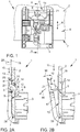
- FIG. 1 shows in a simplified plan view of a window pane assembly 1, which comprises a window pane 2 and a driver 3.
- the driver 3 serves to move the window pane 2 in a frame, not shown here up and down, as indicated by a double arrow 4.
- the driver 2 is for example driven by an electric actuator device. In order to transport the window in both desired directions through the driver 3, this is connected to the window pane 2 in a form-fitting manner.
- FIGS. 2A and 2B show the window assembly 1 in each case in a sectional view along the line AA FIG. 1 ,
- the driver 3 has a receiving recess 5, in which an edge portion 6 of the window pane 2 is received.
- the receiving recess 5 is designed such that the window pane 2 is held in the receiving recess 5 substantially positive fit and preferably substantially free of play.
- the width shown in the side view of the receiving recess 5 corresponds to the width of the window pane 2 at its edge region 6.
- the window pane 2 abuts against the driver 3, so that the driver 3 can move the window pane 2 upward by an upward movement ,
- a locking device 8 is provided.
- the locking device 8 has an elastically displaceable locking lug 9.
- the latch extends in the in FIG. 2A illustrated initial state through the receiving recess 5 and thereby blocks it.
- the detent 9 has at its top a Insertion bevel 10, which faces the receiving recess 5 and the window pane 2.
- the insertion bevel 10 has a first guide section 11 and a second guide section 12, which are aligned with each other in an inclined manner, so that the first guide section 10 encloses a smaller angle with the window pane 2 than the second guide section 12, which is located substantially in the area of the receiving recess 5 or extends therethrough.
- the first guide section 11 is substantially associated with the outer side 13 of the window pane 2.
- the window pane 2 also has a latching recess 14, through which the latching lug 9 extends in regions.
- the underside of the locking lug 9 is flat, so that it extends substantially horizontally through the receiving recess 5.
- the underside of the latching lug 9 is assigned to the lower edge of the latching recess 14, so that the latching lug 9 rests on the lower edge of the latching recess 14. Now, if the driver 3 is pulled down, the tensile force is transmitted through the locking lug 9 on the window pane 2.
- the assembly of the window assembly 1 is very simple.
- the window pane 2 is simply inserted from above into the receiving recess 5, as indicated by an arrow 15, with its edge 7 first.
- the insertion edge 10 then causes the latching lug 9 is displaced out of the region of the receiving recess 5 outwards, as indicated by an arrow 16.
- the locking lug 9 is fixedly formed with a receiving recess 5 to the front limiting side wall 17 of the driver 3.
- the side wall 17 is either itself elastic or elastically held on the driver 3, so that it is elastically displaceable according to arrow 16 to ensure the locking lug 9 from the region of the receiving recess 5 by the insertion of the window 2.
- the window pane 2 can be completely inserted into the receiving recess 5 to the stop, so that the locking recess 14 is then in the region of the locking lug 9. Due to the inherent elasticity of the storage of the locking lug 9, this springs back automatically back into its initial position according to arrow 18, in which they, as in FIG. 2A shown in the locking recess 14 rests to lock the driver 3 on the window pane 2.
- This very simple mounting option has the disadvantage that without further precautions by inserting a manipulation tool 19, which is formed for example as a thin sheet metal element, through an opening gap between a door frame 20 and the window pane 2 to the latching lug 9 only indicated here by arrow 16 in FIG. 2B displaced outwards and thereby the driver 3 can be solved by the window pane 2.
- a manipulation tool 19 which is formed for example as a thin sheet metal element
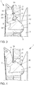
- the latching lug 9 is provided with a catching groove 21.
- FIG. 3 shows the catch groove 21 is located between the first guide portion 11 and the second guide portion 12 of the insertion 10.
- the catch groove 21 extends parallel to the receiving recess 5 over the entire width of the latch 9, as especially in FIG. 1 shown.
- the catch groove 21 has a bottom 22 and two opposite side walls 23 and 24, which are aligned perpendicular to the bottom 22.
- the catching groove 21 is formed in the latching lug 9 in such a way that, in the starting position of the latching lug 9, it lies within the latching recess 14 of the windowpane 2.
- the width B of the catching groove 21 is chosen to be at least as wide as the maximum gap opening between the window 2 and the window frame 20, but narrower than the width of the window pane 2.
- the catch groove 21 prevents in a simple manner that the driver 3 of the window pane 2, as described above, can be solved.
- the manipulation tool 19 has been trapped in the catching groove 21, it can no longer be moved further downwards or the catching lug can be further moved out of the latching recess 14 by the manipulation tool.
- the safety of the window pane assembly 1 is protected from a manipulation attempt in a particularly simple manner. Since the catch groove 21 extends over the entire width of the latching lug 9, it is ensured that a manipulation tool 19 which is pushed onto the latching lug 9 also always passes into the catching groove 21.
- the window pane 2 is provided at its edge 7 with a Ein beneficiafase 26, as in particular in FIGS. 2A and 2B is shown.
- the Ein Industriesfase 26 is formed so broad that when inserting the window pane 2 in the receiving recess 5, the Einzhoufase 26, the catch groove 21 bridged such that the edge 7 during insertion always on the second portion 12 of the insertion bevel 10 of the latch 9 meets, so that the catch 9 is always in the receiving recess 5 releasing position by the insertion of the window 2 can be brought.
Landscapes
- Engineering & Computer Science (AREA)
- Mechanical Engineering (AREA)
- Window Of Vehicle (AREA)
Description
- Die Erfindung betrifft einen Mitnehmer für eine verschiebbare Fensterscheibe, insbesondere eines Kraftfahrzeugs, mit einer Aufnahmevertiefung zur Aufnahme eines Randabschnitts der Fensterscheibe, und mit einer elastisch verlagerbaren Rastnase, die zum Eingriff in eine Rastaussparung der Fensterscheibe ausgebildet ist, um die Fensterscheibe an dem Mitnehmer zu arretieren, wobei die Rastnase in ihrer Ausgangsstellung die Aufnahmevertiefung versperrt und eine der Aufnahmevertiefung zugeordnete Einführschräge aufweist, so dass die Rastnase durch das Einführen der Fensterscheibe in die Aufnahmevertiefung in eine die Aufnahmevertiefung freigebende Stellung verlagert wird.
- Ferner betrifft die Erfindung eine Fensterscheibenanordnung, insbesondere für ein Kraftfahrzeug, mit einer verschiebbaren Fensterscheibe und mit einem mit der Fensterscheibe verbindbaren/verbundenen Mitnehmer.
- Mitnehmer und Fensterscheibenanordnungen der Eingangs genannten Art sind aus dem Stand der Technik bekannt. Verstellbare oder verschiebbare Fensterscheiben in Kraftfahrzeugen sind in der Regel in einem Rahmen geführt und werden durch einen Mitnehmer verstellt, der über eine Antriebseinrichtung entlang einer Führungsbahn angetrieben wird, wodurch die mit dem Mitnehmer verbundene Fensterscheibe angehoben oder abgesenkt werden kann.
- Um das Fenster beispielsweise nach oben zu schieben, reicht es aus, dass der Mitnehmer gegen eine Seite der Fensterscheibe gedrückt wird. Um die Fensterscheibe durch den Mitnehmer auch in die entgegengesetzte Richtung verfahren zu können, muss der Mitnehmer mit der Fensterscheibe fest verbunden sein. Dabei ist es bekannt, den Mitnehmer mit einer Rastnase zu versehen, die eine einfache und insbesondere werkzeuglose Montage des Mitnehmers an der Fensterscheibe erlaubt. Ein entsprechender Mitnehmer ist beispielsweise in der
DE 10 2012 223 825 A1 beschrieben. Der Mitnehmer weist eine Aufnahmevertiefung auf, in welche die Fensterscheibe mit einem Randabschnitt einschiebbar ist. Der Aufnahmevertiefung ist die Rastnase zugeordnet, die die Aufnahmevertiefung in ihrem entspannten Zustand beziehungsweise in ihrer Ausgangsstellung versperrt. Wird die Fensterscheibe in die Aufnahmevertiefung eingeführt, trifft sie auf die Rastnase, welche mit einer Einführschräge versehen ist. Die Einführschräge ist dabei der Aufnahmevertiefung derart zugeordnet, dass sich durch Einführen der Fensterscheibe in die Aufnahmevertiefung die Rastnase aus der Ausgangsstellung in eine die Aufnahmevertiefung freigebende Stellung verlagert beziehungsweise zurückgedrängt wird. Die Fensterscheibe weist eine Rastaufnahme in dem Randabschnitt auf, in welche die Rastnase aufgrund ihrer elastischen Anbindung an den Mitnehmer automatisch einrastet und dadurch formschlüssig die Fensterscheibe an dem Mitnehmer arretiert, wenn die Fensterscheibe entsprechend weit in die Aufnahmevertiefung eingeschoben wurde. - Aus der Offenlegungsschrift
US 2010/313481 ist ebenfalls bereits ein Mitnehmer der eingangs genannten Art bekannt. Auch aus den OffenlegungsschriftenDE 100 39 688 A1 undUS 2009/090064 A1 sind bereits Mitnehmer für Fensterscheiben bekannt, die verlagerbare Rastnasen zum Arretieren der Fensterscheibe an dem Mitnehmer aufweisen. - Es hat sich jedoch herausgestellt, dass diese einfache Art der Montage einen besonderen Nachteil mit sich führt. Unter Zuhilfenahme eines Hilfswerkzeugs lässt sich der Mitnehmer nämlich leicht von der Fensterscheibe lösen, wenn beispielsweise ein schmales Blech durch einen Öffnungsspalt zwischen einem die Fensterscheibe führenden Rahmen, beziehungsweise Türrahmen, und der Fensterscheibe in einen Innenraum, beispielsweise der die Fensterscheibenanordnung aufweisenden Kraftfahrzeugtür, eingeführt und zwischen die Rastnase und die Fensterscheibe geschoben wird, so dass die Rastnase dadurch aus der Rastaussparung der Fensterscheibe herausverlagert wird. In der zuvor genannten Offenlegungsschrift wird versucht, dies durch das Vorsehen einer zusätzlichen Sicherung oder eines zusätzlichen Sicherungselementes zu vermeiden. Die offenbarten Lösungen sind jedoch konstruktiv aufwändig und führen damit auch zu einem entsprechend finanziellen Aufwand bei der Herstellung.
- Der Erfindung liegt die Aufgabe zugrunde, einen Mitnehmer sowie eine Fensterscheibenanordnung mit einem entsprechenden Mitnehmer zu schaffen, die auf einfache und kostengünstige Art und Weise eine missbräuchliche Manipulation der Verbindung zwischen Mitnehmer und Fensterscheibe sicher verhindert.
- Die der Erfindung zugrundeliegende Aufgabe wird durch einen Mitnehmer mit den Merkmalen des Anspruchs 1 gelöst. Dieser hat den Vorteil, dass durch eine sehr einfache konstruktive Maßnahme an der Rastnase die Sicherheit gegen ein unerwünschtes Lösen der Arretierung erhöht wird. Insbesondere verhindert es der erfindungsgemäße Mitnehmer, dass ein Manipulationswerkzeug, das zwischen Rastnase und Fensterscheibe geschoben wird, die Rastnase vollständig aus der Rastaussparung der Fensterscheibe herausverlagern kann. Die Erfindung sieht hierzu vor, dass die Rastnase des Mitnehmers an der Einführschräge eine Fangnut aufweist, die sich parallel zur Aufnahmevertiefung über die gesamte Breite der Rastnase erstreckt.
- Erfindungsgemäß ist also eine Fangnut vorgesehen, die sich über die Einführschräge erstreckt. Dabei erstreckt sich die Fangnut parallel zur Aufnahmevertiefung und damit senkrecht zur üblichen Verlagerungsrichtung der Rastnase, die in der Regel senkrecht zur Ebene der Fensterscheibe liegt. Wird nunmehr ein Manipulationswerkzeug zwischen die Fensterscheibe und die Rastnase eingeführt, so wird die Rastnase maximal so weit aus der Rastaussparung herausverlagert, bis das Manipulationswerkzeug entlang der Einführschräge in die Fangnut rutscht. Dort wird zumindest die Spitze des Manipulationswerkzeugs gefangen. Ein weiteres Einschieben des Manipulationswerkzeugs ist dann nicht mehr möglich. Entsprechend kann die Rastnase nicht weiter aus der Rastaussparung herausverlagert werden, wodurch die Arretierung der Fensterscheibe bestehen beziehungsweise gesichert bleibt.
- Gemäß einer vorteilhaften Weiterbildung der Erfindung ist vorgesehen, dass die Fangnut bei in die Aufnahmevertiefung eingesteckter Fensterscheibe in der Rastaussparung der Fensterscheibe liegt. Dadurch wird gewährleistet, dass, wenn ein Manipulationswerkzeug zwischen Rastnase und Fensterscheibe eingeschoben wird, die Spitze des Manipulationswerkzeugs durch die Einführschräge auf die Fangnut zugeleitet beziehungsweise geschoben wird, die sich aus der Rastöffnung der Fensterscheibe heraus bewegt. Damit wird verhindert, dass das Manipulationswerkzeug auf den zwischen der Fangnut und der der Fensterscheibe zugewandten Spitze der Rastnase liegenden Abschnitt der Einführschräge trifft und die Fangnut dadurch übergeht.
- Weiterhin ist bevorzugt vorgesehen, dass die Fangnut schmaler ausgebildet ist als die Aufnahmevertiefung, insbesondere schmaler als die Fensterscheibe. Durch die schmale Ausbildung der Fangnut wird erreicht, dass die breitere Fensterscheibe beim Einschieben in die Aufnahmevertiefung die Fangnut überbrücken und dadurch die Rastnase vollständig in die die Aufnahmevertiefung freigebende Stellung zurückdrängen kann. Damit wird trotz Vorsehen der Fangnut die einfache Montage der Fensterscheibe an dem Mitnehmer auch weiterhin gewährleistet.
- Es ist ferner bevorzugt vorgesehen, dass die Fangnut mindestens so breit ist, wie die breiteste von dem Manipulationswerkzeug durchgreifbare Öffnung oder Spaltöffnung zwischen Fensterscheibe und beispielsweise Fensterscheibendichtung oder -Rahmen. Dadurch wird gewährleistet, dass jedes durch die entsprechende Öffnung hindurchschiebbares Manipulationswerkzeug oder Hilfswerkzeug sicher in der Fangnut auffangbar ist.
- Auch ist bevorzugt vorgesehen, dass die Einführschräge einen ersten Führungsabschnitt und einen zweiten Führungsabschnitt aufweist, die zueinander geneigt ausgerichtet sind. Die Einführschräge weist somit mindestens zwei unterschiedliche Steigungen beziehungsweise Steigungswinkel auf. Dadurch wird beispielsweise das Einführen der Fensterscheibe in die Aufnahmevertiefung und das Zurückdrängen der Rastnase vereinfacht.
- Vorzugsweise liegt die Fangnut zwischen dem ersten Führungsabschnitt und dem zweiten Führungsabschnitt. Dies hat den Vorteil, dass die Fangnut in einem Knick der Einführschräge vorgesehen ist, wodurch die Fangwirkung der Fangnut erhöht wird. Insbesondere ist vorgesehen, dass der Abschnitt der Einführschräge zwischen der Fangnut und der Spitze der Rastnase in einem größeren Winkel zur Einschieberichtung der Fensterscheibe steht als der erste Führungsabschnitt. Dadurch wird ein Hilfswerkezeug steil in die Fangnut geleitet, wodurch die Sicherheit vor einem Überbrücken der Fangnut durch das Hilfswerkzeug weiter erhöht wird.
- Gemäß einer vorteilhaften Weiterbildung der Erfindung ist außerdem vorgesehen, dass mindestens eine Seitenwand der Fangnut zumindest im Wesentlichen senkrecht zu einem Boden der Fangnut ausgerichtet ist. Dadurch wird ein rechter Winkel zwischen der Seitenwand und dem Boden der Fangnut gebildet, in welchem das Manipulationswerkezug besonders sicher einfangbar ist. Insbesondere ist vorgesehen, dass es sich bei der genannten Seitenwand um die der Fensterscheibe zugewandten Seitenwand der Fangnut handelt. Besonders bevorzugt ist vorgesehen, dass sich diese Seitenwand parallel zur Fensterscheibe erstreckt, wenn die Rastnase durch das Manipulationswerkzeug entsprechend weit aus der Rastaussparung der Fensterscheibe aus verlagert wurde, um eine sichere Arretierung des Hilfswerkzeugs in der Fangnut zu gewährleisten.
- Die erfindungsgemäße Fensterscheibenanordnung mit den Merkmalen des Anspruchs 7 zeichnet sich durch den erfindungsgemäßen Mitnehmer aus. Es ergeben sich für die Fensterscheibenanordnung die bereits genannten Vorteile. Insbesondere verhindert die erfindungsgemäße Fensterscheibenanordnung, dass durch das Einschieben eines einfachen Manipulationswerkzeugs die Rastnase aus der Rastaussparung der Fensterscheibe herausverlagert werden kann.
- Besonders bevorzugt ist vorgesehen, dass die Fensterscheibe an ihrem dem Mitnehmer zugewandten Rand wenigstens eine Einführfase aufweist. Diese Einführfase kann beispielsweise durch einen Scheibenschliff oder Dergleichen gebildet sein. Die Einführfase erleichtert das Einschieben der Fensterscheibe in die Aufnahmevertiefung und insbesondere das Verlagern der Rastnase in die die Aufnahmevertiefung freigebenden Stellung.
- Weiterhin ist bevorzugt vorgesehen, dass die Einführfase derart ausgebildet ist, dass sie beim Einschieben der Fensterscheibe in die Aufnahmevertiefung die Fangnut der Rastnase überbrückt. Die Einführfase ist also derart groß ausgebildet, dass die Fensterscheibe beim Einschieben in die Aufnahmevertiefung selbst nicht mit der Fangnut zusammenwirkt. Durch eine entsprechend große Einführfase trifft die Fensterscheibe stattdessen direkt auf den zweiten Führungsabschnitt der Einführschräge der Rastnase. Somit wird einerseits die Sicherheit gegen unbefugtes Lösen der Verbindung zwischen Mitnehmer und Fensterscheibe gewährleistet, und gleichzeitig die einfache Montierbarkeit der Fensterscheibe an dem Mitnehmer beibehalten.
- Im Folgenden soll die Erfindung anhand eines Ausführungsbeispiels näher erläutert werden. Dazu zeigen:
- Figur 1
- einen Mitnehmer einer Fensterscheibenanordnung in einer Draufsicht,
- Figuren 2A und B
- den Mitnehmer in einer Seitenansicht in unterschiedlichen Situationen,
- Figur 3
- eine Detailansicht des Mitnehmers und
- Figur 4
- die Detailansicht in einer Gebrauchsstellung.
-
Figur 1 zeigt in einer vereinfachten Draufsicht eine Fensterscheibenanordnung 1, die eine Fensterscheibe 2 und einen Mitnehmer 3 umfasst. Der Mitnehmer 3 dient dazu, die Fensterscheibe 2 in einem hier nicht dargestellten Rahmen nach oben und nach unten zu verschieben, wie durch einen Doppelpfeil 4 angedeutet. Der Mitnehmer 2 wird dazu beispielsweise von einer elektrischen Aktoreinrichtung angetrieben. Um die Fensterscheibe in beide gewünschten Richtungen durch den Mitnehmer 3 zu transportieren, ist dieser mit der Fensterscheibe 2 formschlüssig verbunden. -
Figuren 2A und 2B zeigen dazu die Fensterscheibenanordnung 1 jeweils in einer Schnittdarstellung entlang der Linie A-A ausFigur 1 . - Der Mitnehmer 3 weist eine Aufnahmevertiefung 5 auf, in welcher ein Randabschnitt 6 der Fensterscheibe 2 aufgenommen ist. Die Aufnahmevertiefung 5 ist dabei derart ausgebildet, dass die Fensterscheibe 2 in der die Aufnahmevertiefung 5 im Wesentlichen formschlüssig und vorzugsweise im Wesentlichen spielfrei gehalten ist. Insbesondere entspricht dabei die in der Seitenansicht dargestellte Breite der Aufnahmevertiefung 5 der Breite der Fensterscheibe 2 an ihrem Randbereich 6. An ihrem Außenrand 7 stößt die Fensterscheibe 2 gegen den Mitnehmer 3, so dass der Mitnehmer 3 durch eine Aufwärtsbewegung die Fensterscheibe 2 nach oben verfahren kann. Um die Fensterscheibe 2 auch in die entgegengesetzte Richtung bewegen zu können, ist eine Rastvorrichtung 8 vorgesehen.
- Die Rastvorrichtung 8 weist eine elastisch verlagerbare Rastnase 9 auf. Die Rastnase erstreckt sich in dem in
Figur 2A dargestellten Ausgangszustand durch die Aufnahmevertiefung 5 hindurch und versperrt sie dadurch. Die Rastnase 9 weist an ihrer Oberseite eine Einführschräge 10 auf, die der Aufnahmevertiefung 5 beziehungsweise der Fensterscheibe 2 zugewandt ist. Die Einführschräge 10 weist einen ersten Führungsabschnitt 11 sowie einen zweiten Führungsabschnitt 12 auf, die zueinander geneigt ausgerichtet sind, so dass der erste Führungsabschnitt 10 einen kleineren Winkel mit der Fensterscheibe 2 einschließt als der zweite Führungsabschnitt 12, der sich im Wesentlichen im Bereich der Aufnahmevertiefung 5 beziehungsweise durch diese hindurch erstreckt. Der erste Führungsabschnitt 11 ist im Wesentlichen der Außenseite 13 der Fensterscheibe 2 zugeordnet. Die Fensterscheibe 2 weist weiterhin eine Rastaussparung 14 auf, durch welche sich die Rastnase 9 bereichsweise hindurch erstreckt. Die Unterseite der Rastnase 9 ist eben ausgebildet, so dass sie sich im Wesentlichen horizontal durch die Aufnahmevertiefung 5 erstreckt. Dabei ist die Unterseite der Rastnase 9 dem unteren Rand der Rastaussparung 14 zugeordnet, so dass die Rastnase 9 auf dem unteren Rand der Rastaussparung 14 aufliegt. Wird nun der Mitnehmer 3 nach unten gezogen, so wird die Zugkraft durch die Rastnase 9 auf die Fensterscheibe 2 übertragen. - Wie in
Figur 2B gezeigt, gestaltet sich die Montage der Fensterscheibenanordnung 1 sehr einfach. Zur Montage wird einfach die Fensterscheibe 2 von oben in die Aufnahmeaussparung 5, wie durch einen Pfeil 15 angedeutet, mit ihrem Rand 7 zuerst eingeschoben. Dabei trifft der Rand 7 auf die Einführschräge 10 der Rastnase 9. Die Einführschräge 10 bewirkt dann, dass die Rastnase 9 aus dem Bereich der Aufnahmevertiefung 5 heraus nach außen verlagert wird, wie durch einen Pfeil 16 angedeutet. Vorliegend ist die Rastnase 9 fest mit einer die Aufnahmevertiefung 5 nach vorne begrenzenden Seitenwand 17 des Mitnehmers 3 ausgebildet. Die Seitenwand 17 ist dabei entweder selbst elastisch ausgebildet oder elastisch an dem Mitnehmer 3 gehalten, so dass sie gemäß Pfeil 16 elastisch verlagerbar ist, um die Rastnase 9 aus dem Bereich der Aufnahmevertiefung 5 durch das Einschieben der Fensterscheibe 2 zu gewährleisten. Sobald die Rastnase 9 aus ihrer Ausgangsstellung in die die Aufnahmevertiefung 5 freigebende Stellung, wie sie inFigur 2B gezeigt ist, verlagert wurde, kann die Fensterscheibe 2 vollständig in die Aufnahmevertiefung 5 bis zum Anschlag eingeschoben werden, so dass die Rastaussparung 14 dann im Bereich der Rastnase 9 liegt. Durch die Eigenelastizität der Lagerung der Rastnase 9, federt diese wieder selbsttätig zurück in ihre Ausgangsstellung gemäß Pfeil 18, in welcher sie, wie inFigur 2A gezeigt, in der Rastaussparung 14 einliegt, um den Mitnehmer 3 an der Fensterscheibe 2 zu arretieren. - Diese sehr einfache Montagemöglichkeit hat den Nachteil, dass ohne weitere Vorkehrungen durch Einschieben eines Manipulationswerkzeuges 19, das beispielsweise als dünnes Blechelement ausgebildet ist, durch einen Öffnungsspalt zwischen einem hier nur angedeuteten Türrahmen 20 und der Fensterscheibe 2 bis zur Rastnase 9 die Rastnase 9 gemäß Pfeil 16 in
Figur 2B nach außen verlagert und dadurch der Mitnehmer 3 von der Fensterscheibe 2 gelöst werden kann. - Um dies zu vermeiden ist vorliegend vorgesehen, dass die Rastnase 9 mit einer Fangnut 21 versehen ist.
-
Figur 3 zeigt hierzu eine vergrößerte Detailansicht der Rastnase 9 mit der Fangnut 21. Die Fangnut 21 liegt zwischen dem ersten Führungsabschnitt 11 und dem zweiten Führungsabschnitt 12 der Einführschräge 10. Die Fangnut 21 erstreckt sich parallel zu der Aufnahmevertiefung 5 über die gesamte Breite der Rastnase 9, wie insbesondere inFigur 1 gezeigt. Die Fangnut 21 weist einen Boden 22 sowie zwei gegenüberliegende Seitenwände 23 und 24 auf, die senkrecht zu dem Boden 22 ausgerichtet sind. Die Fangnut 21 ist derart in der Rastnase 9 ausgebildet, dass sie in der Ausgangsstellung der Rastnase 9, innerhalb der Rastaussparung 14 der Fensterscheibe 2 liegt. Die Breite B der Fangnut 21 ist dabei mindestens so breit gewählt, wie die maximale Spaltöffnung zwischen dem Fenster 2 und dem Fensterrahmen 20, jedoch schmaler als die Breite der Fensterscheibe 2. - Die Fangnut 21 verhindert auf einfache Art und Weise, dass der Mitnehmer 3 von der Fensterscheibe 2, wie zuvor beschrieben, gelöst werden kann. Ein Manipulationswerkzeug 19, das durch den Öffnungsspalt zwischen Türrahmen 20 und Fenster 2 passt, und entlang der Fensterscheibe 2, wie zuvor beschrieben, bis auf die Rastnase 9 geschoben wird, dringt diese zunächst ein Stück weit aus der Rastaussparung 14 heraus, bis die Spitze 25 des Manipulationswerkzeugs in die Fangnut 21 gerät, die aus der Rastaussparung 14 herausbewegt wurde. Sobald das Manipulationswerkzeug 19 dadurch in der Fangnut 21 gefangen wurde, kann es nicht mehr weiter nach unten verschoben oder die Rastnase durch das Manipulationswerkzeug weiter aus der Rastaussparung 14 herausbewegt werden. Hierdurch wird auf besonders einfache Art und Weise die Sicherheit der Fensterscheibenanordnung 1 vor einem Manipulationsversuch geschützt. Da sich die Fangnut 21 über die gesamte Breite der Rastnase 9 erstreckt, wird gewährleistet, dass ein Manipulationswerkzeug 19, das auf die Rastnase 9 geschoben wird, auch stets in die Fangnut 21 gelangt.
- Vorteilhafterweise ist die Fensterscheibe 2 an ihrem Rand 7 mit einer Einführfase 26 versehen, wie sie insbesondere in
Figuren 2A und 2B gezeigt ist. Die Einführfase 26 ist dabei derart breit ausgebildet, dass beim Einschieben der Fensterscheibe 2 in die Aufnahmevertiefung 5 die Einführfase 26 die Fangnut 21 derart überbrückt, dass der Rand 7 beim Einführen stets auf den zweiten Abschnitt 12 der Einführschräge 10 der Rastnase 9 trifft, so dass die Rastnase 9 stets in die die Aufnahmevertiefung 5 freigebende Stellung durch das Einführen der Fensterscheibe 2 verbringbar ist.
Claims (9)
- Mitnehmer (3) für eine verschiebbare Fensterscheibe (2), insbesondere eines Kraftfahrzeugs, mit einer Aufnahmevertiefung (5) zur Aufnahme eines Randabschnitts (6) der Fensterscheibe (2), und mit einer elastisch verlagerbaren Rastnase (5), die zum Eingriff in eine Rastaussparung (14) der Fensterscheibe (2) ausgebildet ist, um die Fensterscheibe an dem Mitnehmer (3) zu arretieren, wobei die Rastnase (9) in ihrer Ausgangsstellung die Aufnahmevertiefung (5) versperrt und eine der Aufnahmevertiefung (5) zugeordnete Einführschräge (10) aufweist, so dass die Rastnase (9) durch das Einführen der Fensterscheibe (2) in die Aufnahmevertiefung (5) in eine die Aufnahmevertiefung freigebende Stellung verlagert wird, wobei die Rastnase (9) an der Einführschräge (10) eine Fangnut (21) aufweist, dadurch gekennzeichnet, dass sich die Fangnut (21) parallel zur Aufnahmevertiefung (5) über die gesamte Breite der Rastnase (9) erstreckt.
- Mitnehmer nach Anspruch 1, dadurch gekennzeichnet, dass die Fangnut (21) bei in die Aufnahmevertiefung (5) eingesteckter Fensterscheibe (2) in der Rastaussparung (14) der Fensterscheibe (2) liegt.
- Mitnehmer nach einem der vorhergehenden Ansprüche, dadurch gekennzeichnet, dass die Fangnut (21) schmaler ausgebildet ist als die Aufnahmevertiefung (5), insbesondere schmaler als die Fensterscheibe (2).
- Mitnehmer nach einem der vorhergehenden Ansprüche, dadurch gekennzeichnet, dass die Einführschräge (10) einen ersten Führungsabschnitt (11) und einen zweiten Führungsabschnitt (12) aufweist, die zueinander geneigt ausgerichtet sind.
- Mitnehmer nach Anspruch 4, dadurch gekennzeichnet, dass die Fangnut (21) zwischen dem ersten Führungsabschnitt (11) und dem zweiten Führungsabschnitt (12) liegt.
- Mitnehmer nach einem der vorhergehenden Ansprüche, dadurch gekennzeichnet, dass mindestens eine Seitenwand (23,24) der Fangnut (21) zumindest im Wesentlichen senkrecht zu einem Boden (22) der Fangnut (21) ausgerichtet ist.
- Fensterscheibenanordnung (1), insbesondere für ein Kraftfahrzeug, mit einer verschiebbaren Fensterscheibe (2) und mit einem mit der Fensterscheibe (2) verbindbaren/verbundenen Mitnehmer (3), gekennzeichnet durch die Ausbildung des Mitnehmers (3) nach einem oder mehreren der vorhergehenden Ansprüche.
- Fensterscheibenanordnung nach Anspruch 7, dadurch gekennzeichnet, dass die Fensterscheibe (2) an ihrem dem Mitnehmer (3) zugewandten Rand (7) wenigstens eine Einführfase (26) aufweist.
- Fensterscheibenanordnung nach Anspruch 8, dadurch gekennzeichnet, dass die Einführfase (26) beim Einschieben der Fensterscheibe (2) in die Aufnahmevertiefung (5) die Fangnut (21) der Rastnase (9) überbrückt.
Applications Claiming Priority (2)
| Application Number | Priority Date | Filing Date | Title |
|---|---|---|---|
| DE102014205548.2A DE102014205548A1 (de) | 2014-03-25 | 2014-03-25 | Mitnehmer für eine verschiebbare Fensterscheibe, Fensterscheibenanordnung |
| PCT/EP2015/055663 WO2015144519A1 (de) | 2014-03-25 | 2015-03-18 | Mitnehmer für eine verschiebbare fensterscheibe, fensterscheibenanordnung |
Publications (2)
| Publication Number | Publication Date |
|---|---|
| EP3122976A1 EP3122976A1 (de) | 2017-02-01 |
| EP3122976B1 true EP3122976B1 (de) | 2018-07-18 |
Family
ID=52692634
Family Applications (1)
| Application Number | Title | Priority Date | Filing Date |
|---|---|---|---|
| EP15710777.2A Active EP3122976B1 (de) | 2014-03-25 | 2015-03-18 | Mitnehmer für eine verschiebbare fensterscheibe, fensterscheibenanordnung |
Country Status (5)
| Country | Link |
|---|---|
| US (1) | US10246926B2 (de) |
| EP (1) | EP3122976B1 (de) |
| CN (1) | CN106460439B (de) |
| DE (1) | DE102014205548A1 (de) |
| WO (1) | WO2015144519A1 (de) |
Families Citing this family (8)
| Publication number | Priority date | Publication date | Assignee | Title |
|---|---|---|---|---|
| DE202016107095U1 (de) * | 2016-12-19 | 2018-03-21 | Brose Fahrzeugteile Gmbh & Co. Kommanditgesellschaft, Bamberg | Schienengleiter für einen Seilfensterheber eines Kraftfahrzeugs |
| DE102018204432A1 (de) | 2018-03-22 | 2019-09-26 | Brose Fahrzeugteile Gmbh & Co. Kommanditgesellschaft, Bamberg | Mitnehmer für einen Fahrzeugfensterheber |
| DE102018206224B4 (de) * | 2018-04-23 | 2021-03-18 | Brose Fahrzeugteile Se & Co. Kommanditgesellschaft, Bamberg | Fensterheberbaugruppe mit einem gegen ein missbräuchliches Lösen gesicherten Mittnehmer |
| DE102019107512A1 (de) * | 2019-03-25 | 2020-10-01 | Volkswagen Aktiengesellschaft | Mitnehmer für eine Fensterheberbaugruppe |
| CN110939350A (zh) * | 2019-10-31 | 2020-03-31 | 徐州积木电子科技有限公司 | 一种温控式电动开窗器的连接件 |
| DE102020101004A1 (de) * | 2020-01-17 | 2020-12-31 | Audi Aktiengesellschaft | Fensterheberanordnung einer Fahrzeugtür |
| DE102021205646A1 (de) * | 2021-06-02 | 2022-12-08 | Brose Fahrzeugteile Se & Co. Kommanditgesellschaft, Bamberg | Fensterheberbaugruppe mit einem Mitnehmer für eine Fensterscheibe |
| DE102021209737A1 (de) * | 2021-09-03 | 2023-03-09 | Brose Fahrzeugteile Se & Co. Kommanditgesellschaft, Bamberg | Fensterheberbaugruppe und Mitnehmer für eine Fensterscheibe |
Family Cites Families (22)
| Publication number | Priority date | Publication date | Assignee | Title |
|---|---|---|---|---|
| US4866895A (en) * | 1989-03-06 | 1989-09-19 | General Motors Corporation | Glass to sash channel attachment |
| FR2709705B1 (fr) | 1993-09-09 | 1995-10-06 | Peugeot | Chariot de lève-vitre pour véhicule automobile, et procédé pour son assemblage avec une vitre. |
| DE29503036U1 (de) * | 1995-02-23 | 1995-04-20 | Brose Fahrzeugteile Gmbh & Co Kg, 96450 Coburg | Vorrichtung zum Verbinden einer Fensterscheibe mit einem Fensterheber |
| JP3355863B2 (ja) * | 1995-04-20 | 2002-12-09 | 株式会社ニフコ | ガラスホルダー及び該ガラスホルダーを用いた窓ガラスの取付方法 |
| DE10039688B4 (de) * | 2000-08-14 | 2004-07-08 | Küster Automotive Door Systems GmbH | Vorrichtung zur Befestigung einer Fensterscheibe eines Kraftfahrzeuges an einer Führungsvorrichtung eines Fensterhebers, insbesondere Mitnehmer |
| FR2820451B1 (fr) * | 2001-02-06 | 2003-08-29 | Meritor Light Vehicle Sys Ltd | Curseur de leve-vitre pour vitre coulissante |
| ES1055444Y (es) * | 2003-08-26 | 2004-03-01 | Castellon Melchor Daumal | Pinza de sujecion para cristales en elevalunas de automoviles. |
| JP3962000B2 (ja) * | 2003-09-22 | 2007-08-22 | マツダ株式会社 | ガラス固定グロメット |
| DE102004031805A1 (de) | 2004-07-01 | 2006-01-26 | Daimlerchrysler Ag | Fensterhebeeinrichtung |
| WO2007140605A1 (en) * | 2006-06-06 | 2007-12-13 | Magna Closures Inc. | Snap-in lifter plate |
| EP2152996B1 (de) * | 2007-05-09 | 2014-09-24 | Magna Closures Inc. | Fensterstelleranordnung für ein fahrzeug |
| US20090090064A1 (en) * | 2007-10-09 | 2009-04-09 | Tudora Spiridon-Sorin S | Lifter plate with energy absorption members |
| DE202008006718U1 (de) * | 2008-05-16 | 2009-09-24 | Brose Fahrzeugteile Gmbh & Co. Kommanditgesellschaft, Hallstadt | Fensterheber mit einem Schienengleiter |
| US20100088964A1 (en) * | 2008-10-10 | 2010-04-15 | Gm Global Technology Operations, Inc. | Snap-in glass retention for a vehicle door |
| US8146293B2 (en) * | 2009-06-16 | 2012-04-03 | Gm Global Technology Operations, Llc | Double acting snap-in glass retention for a vehicle door |
| CN103069094B (zh) * | 2010-06-30 | 2016-04-06 | Hi-Lex株式会社 | 车窗开闭调节器 |
| US8739467B2 (en) * | 2011-12-19 | 2014-06-03 | Chrysler Group Llc | Window regulator glass attachment guide cover |
| DE202012101871U1 (de) | 2012-01-02 | 2013-04-04 | Brose Fahrzeugteile Gmbh & Co. Kommanditgesellschaft, Hallstadt | Fensterheberbaugruppe mit Diebstahlschutz |
| DE102012208562A1 (de) * | 2012-05-22 | 2013-11-28 | Brose Fahrzeugteile Gmbh & Co. Kg, Hallstadt | Mitnehmer zum Anbinden einer Fensterscheibe an einen Fensterheber für Kraftfahrzeuge |
| CN202718517U (zh) * | 2012-08-09 | 2013-02-06 | 上海通用汽车有限公司 | 汽车摇窗机托架 |
| CN203113782U (zh) * | 2013-02-06 | 2013-08-07 | 山河建设集团有限公司 | 反梁支模固定夹具 |
| CN203285230U (zh) * | 2013-06-13 | 2013-11-13 | 上海宏宝汽配有限公司 | 一种绳轮式玻璃升降器用玻璃托架 |
-
2014
- 2014-03-25 DE DE102014205548.2A patent/DE102014205548A1/de not_active Withdrawn
-
2015
- 2015-03-18 CN CN201580015907.8A patent/CN106460439B/zh active Active
- 2015-03-18 WO PCT/EP2015/055663 patent/WO2015144519A1/de not_active Ceased
- 2015-03-18 EP EP15710777.2A patent/EP3122976B1/de active Active
-
2016
- 2016-09-26 US US15/275,758 patent/US10246926B2/en active Active
Non-Patent Citations (1)
| Title |
|---|
| None * |
Also Published As
| Publication number | Publication date |
|---|---|
| WO2015144519A1 (de) | 2015-10-01 |
| DE102014205548A1 (de) | 2015-10-01 |
| CN106460439A (zh) | 2017-02-22 |
| CN106460439B (zh) | 2018-12-04 |
| US10246926B2 (en) | 2019-04-02 |
| US20170008378A1 (en) | 2017-01-12 |
| EP3122976A1 (de) | 2017-02-01 |
Similar Documents
| Publication | Publication Date | Title |
|---|---|---|
| EP3122976B1 (de) | Mitnehmer für eine verschiebbare fensterscheibe, fensterscheibenanordnung | |
| EP2295681B2 (de) | Öffnungs- und/oder Schließmechanismus an Türen, Klappen oder dgl., insbesondere an Fahrzeugen | |
| EP3165703A2 (de) | Absenkbare dichtungsvorrichtung | |
| EP3296493B1 (de) | Tragsystem für eine schiebetür | |
| DE202007004524U1 (de) | Arretiervorrichtung für einen Kraftfahrzeugsitz | |
| EP2843169B1 (de) | Schiebetür mit einem Tragsystem | |
| DE102017007060B4 (de) | Anordnung aus einer Vorrichtung zur Aufnahme eines Gegenstands in einem Kraftfahrzeug und einem Gegenstand | |
| DE202016101097U1 (de) | Verriegelungseinrichtung und dazugehörige Schiebetüranlage | |
| DE102015212355B4 (de) | Mitnehmeranordnung | |
| EP2759666B1 (de) | Beschlaganordnung mit einem Profilelement | |
| DE10107382A9 (de) | Vorrichtung zur verriegelung, halterung und anpressung von tueren oder fenstern an einem tuer- oder fensterrahmen | |
| DE102009033939B4 (de) | Wohndachfenster sowie Verfahren zum Befestigen eines Abdeckblechs | |
| WO2008015026A1 (de) | Türmodul mit fensterhebereinrichtung | |
| EP3175064A1 (de) | Torantriebsvorrichtung mit sperreinrichtung sowie damit versehenes tor | |
| EP3553260B1 (de) | Falleneinsatz mit tagstellung zur bedingten freigabe einer schlossfalle eines türschlossmechanismus | |
| EP2085543B1 (de) | Schloss | |
| EP2317047A2 (de) | Beschlaganordnung | |
| EP3179017A1 (de) | Falleneinsatz zur bedingten freigabe einer schlossfalle eines türschlossmechanismus | |
| EP1905631A1 (de) | Sicherheits-Bremsvorrichtung eines Schiebedachdeckels | |
| DE102015111300B4 (de) | Fahrzeugschiebedach | |
| EP3085876B1 (de) | Absenkdichtungsvorrichtung | |
| EP2132391A1 (de) | Treibstangenanordnung mit mindestens einer treibstange und mindestens einem treibstangenführungselement | |
| DE102015108737A1 (de) | Kraftfahrzeugschloss | |
| DE102014109437A1 (de) | Beschlag für eine Schiebetür | |
| EP3521540A1 (de) | Kraftfahrzeugschloss |
Legal Events
| Date | Code | Title | Description |
|---|---|---|---|
| STAA | Information on the status of an ep patent application or granted ep patent |
Free format text: STATUS: THE INTERNATIONAL PUBLICATION HAS BEEN MADE |
|
| PUAI | Public reference made under article 153(3) epc to a published international application that has entered the european phase |
Free format text: ORIGINAL CODE: 0009012 |
|
| STAA | Information on the status of an ep patent application or granted ep patent |
Free format text: STATUS: REQUEST FOR EXAMINATION WAS MADE |
|
| 17P | Request for examination filed |
Effective date: 20161025 |
|
| AK | Designated contracting states |
Kind code of ref document: A1 Designated state(s): AL AT BE BG CH CY CZ DE DK EE ES FI FR GB GR HR HU IE IS IT LI LT LU LV MC MK MT NL NO PL PT RO RS SE SI SK SM TR |
|
| AX | Request for extension of the european patent |
Extension state: BA ME |
|
| DAV | Request for validation of the european patent (deleted) | ||
| DAX | Request for extension of the european patent (deleted) | ||
| GRAP | Despatch of communication of intention to grant a patent |
Free format text: ORIGINAL CODE: EPIDOSNIGR1 |
|
| STAA | Information on the status of an ep patent application or granted ep patent |
Free format text: STATUS: GRANT OF PATENT IS INTENDED |
|
| INTG | Intention to grant announced |
Effective date: 20180212 |
|
| GRAS | Grant fee paid |
Free format text: ORIGINAL CODE: EPIDOSNIGR3 |
|
| GRAA | (expected) grant |
Free format text: ORIGINAL CODE: 0009210 |
|
| STAA | Information on the status of an ep patent application or granted ep patent |
Free format text: STATUS: THE PATENT HAS BEEN GRANTED |
|
| AK | Designated contracting states |
Kind code of ref document: B1 Designated state(s): AL AT BE BG CH CY CZ DE DK EE ES FI FR GB GR HR HU IE IS IT LI LT LU LV MC MK MT NL NO PL PT RO RS SE SI SK SM TR |
|
| REG | Reference to a national code |
Ref country code: GB Ref legal event code: FG4D Free format text: NOT ENGLISH |
|
| REG | Reference to a national code |
Ref country code: CH Ref legal event code: EP |
|
| REG | Reference to a national code |
Ref country code: IE Ref legal event code: FG4D Free format text: LANGUAGE OF EP DOCUMENT: GERMAN |
|
| REG | Reference to a national code |
Ref country code: AT Ref legal event code: REF Ref document number: 1019549 Country of ref document: AT Kind code of ref document: T Effective date: 20180815 |
|
| REG | Reference to a national code |
Ref country code: DE Ref legal event code: R096 Ref document number: 502015005128 Country of ref document: DE |
|
| REG | Reference to a national code |
Ref country code: NL Ref legal event code: MP Effective date: 20180718 |
|
| REG | Reference to a national code |
Ref country code: LT Ref legal event code: MG4D |
|
| PG25 | Lapsed in a contracting state [announced via postgrant information from national office to epo] |
Ref country code: NL Free format text: LAPSE BECAUSE OF FAILURE TO SUBMIT A TRANSLATION OF THE DESCRIPTION OR TO PAY THE FEE WITHIN THE PRESCRIBED TIME-LIMIT Effective date: 20180718 |
|
| PG25 | Lapsed in a contracting state [announced via postgrant information from national office to epo] |
Ref country code: FI Free format text: LAPSE BECAUSE OF FAILURE TO SUBMIT A TRANSLATION OF THE DESCRIPTION OR TO PAY THE FEE WITHIN THE PRESCRIBED TIME-LIMIT Effective date: 20180718 Ref country code: LT Free format text: LAPSE BECAUSE OF FAILURE TO SUBMIT A TRANSLATION OF THE DESCRIPTION OR TO PAY THE FEE WITHIN THE PRESCRIBED TIME-LIMIT Effective date: 20180718 Ref country code: PL Free format text: LAPSE BECAUSE OF FAILURE TO SUBMIT A TRANSLATION OF THE DESCRIPTION OR TO PAY THE FEE WITHIN THE PRESCRIBED TIME-LIMIT Effective date: 20180718 Ref country code: GR Free format text: LAPSE BECAUSE OF FAILURE TO SUBMIT A TRANSLATION OF THE DESCRIPTION OR TO PAY THE FEE WITHIN THE PRESCRIBED TIME-LIMIT Effective date: 20181019 Ref country code: SE Free format text: LAPSE BECAUSE OF FAILURE TO SUBMIT A TRANSLATION OF THE DESCRIPTION OR TO PAY THE FEE WITHIN THE PRESCRIBED TIME-LIMIT Effective date: 20180718 Ref country code: BG Free format text: LAPSE BECAUSE OF FAILURE TO SUBMIT A TRANSLATION OF THE DESCRIPTION OR TO PAY THE FEE WITHIN THE PRESCRIBED TIME-LIMIT Effective date: 20181018 Ref country code: IS Free format text: LAPSE BECAUSE OF FAILURE TO SUBMIT A TRANSLATION OF THE DESCRIPTION OR TO PAY THE FEE WITHIN THE PRESCRIBED TIME-LIMIT Effective date: 20181118 Ref country code: RS Free format text: LAPSE BECAUSE OF FAILURE TO SUBMIT A TRANSLATION OF THE DESCRIPTION OR TO PAY THE FEE WITHIN THE PRESCRIBED TIME-LIMIT Effective date: 20180718 Ref country code: NO Free format text: LAPSE BECAUSE OF FAILURE TO SUBMIT A TRANSLATION OF THE DESCRIPTION OR TO PAY THE FEE WITHIN THE PRESCRIBED TIME-LIMIT Effective date: 20181018 |
|
| PG25 | Lapsed in a contracting state [announced via postgrant information from national office to epo] |
Ref country code: HR Free format text: LAPSE BECAUSE OF FAILURE TO SUBMIT A TRANSLATION OF THE DESCRIPTION OR TO PAY THE FEE WITHIN THE PRESCRIBED TIME-LIMIT Effective date: 20180718 Ref country code: AL Free format text: LAPSE BECAUSE OF FAILURE TO SUBMIT A TRANSLATION OF THE DESCRIPTION OR TO PAY THE FEE WITHIN THE PRESCRIBED TIME-LIMIT Effective date: 20180718 Ref country code: LV Free format text: LAPSE BECAUSE OF FAILURE TO SUBMIT A TRANSLATION OF THE DESCRIPTION OR TO PAY THE FEE WITHIN THE PRESCRIBED TIME-LIMIT Effective date: 20180718 |
|
| REG | Reference to a national code |
Ref country code: DE Ref legal event code: R097 Ref document number: 502015005128 Country of ref document: DE |
|
| PG25 | Lapsed in a contracting state [announced via postgrant information from national office to epo] |
Ref country code: ES Free format text: LAPSE BECAUSE OF FAILURE TO SUBMIT A TRANSLATION OF THE DESCRIPTION OR TO PAY THE FEE WITHIN THE PRESCRIBED TIME-LIMIT Effective date: 20180718 Ref country code: CZ Free format text: LAPSE BECAUSE OF FAILURE TO SUBMIT A TRANSLATION OF THE DESCRIPTION OR TO PAY THE FEE WITHIN THE PRESCRIBED TIME-LIMIT Effective date: 20180718 Ref country code: IT Free format text: LAPSE BECAUSE OF FAILURE TO SUBMIT A TRANSLATION OF THE DESCRIPTION OR TO PAY THE FEE WITHIN THE PRESCRIBED TIME-LIMIT Effective date: 20180718 Ref country code: RO Free format text: LAPSE BECAUSE OF FAILURE TO SUBMIT A TRANSLATION OF THE DESCRIPTION OR TO PAY THE FEE WITHIN THE PRESCRIBED TIME-LIMIT Effective date: 20180718 Ref country code: EE Free format text: LAPSE BECAUSE OF FAILURE TO SUBMIT A TRANSLATION OF THE DESCRIPTION OR TO PAY THE FEE WITHIN THE PRESCRIBED TIME-LIMIT Effective date: 20180718 |
|
| PLBE | No opposition filed within time limit |
Free format text: ORIGINAL CODE: 0009261 |
|
| STAA | Information on the status of an ep patent application or granted ep patent |
Free format text: STATUS: NO OPPOSITION FILED WITHIN TIME LIMIT |
|
| PG25 | Lapsed in a contracting state [announced via postgrant information from national office to epo] |
Ref country code: DK Free format text: LAPSE BECAUSE OF FAILURE TO SUBMIT A TRANSLATION OF THE DESCRIPTION OR TO PAY THE FEE WITHIN THE PRESCRIBED TIME-LIMIT Effective date: 20180718 Ref country code: SK Free format text: LAPSE BECAUSE OF FAILURE TO SUBMIT A TRANSLATION OF THE DESCRIPTION OR TO PAY THE FEE WITHIN THE PRESCRIBED TIME-LIMIT Effective date: 20180718 Ref country code: SM Free format text: LAPSE BECAUSE OF FAILURE TO SUBMIT A TRANSLATION OF THE DESCRIPTION OR TO PAY THE FEE WITHIN THE PRESCRIBED TIME-LIMIT Effective date: 20180718 |
|
| 26N | No opposition filed |
Effective date: 20190423 |
|
| PG25 | Lapsed in a contracting state [announced via postgrant information from national office to epo] |
Ref country code: SI Free format text: LAPSE BECAUSE OF FAILURE TO SUBMIT A TRANSLATION OF THE DESCRIPTION OR TO PAY THE FEE WITHIN THE PRESCRIBED TIME-LIMIT Effective date: 20180718 |
|
| PG25 | Lapsed in a contracting state [announced via postgrant information from national office to epo] |
Ref country code: MC Free format text: LAPSE BECAUSE OF FAILURE TO SUBMIT A TRANSLATION OF THE DESCRIPTION OR TO PAY THE FEE WITHIN THE PRESCRIBED TIME-LIMIT Effective date: 20180718 |
|
| REG | Reference to a national code |
Ref country code: CH Ref legal event code: PL |
|
| PG25 | Lapsed in a contracting state [announced via postgrant information from national office to epo] |
Ref country code: LU Free format text: LAPSE BECAUSE OF NON-PAYMENT OF DUE FEES Effective date: 20190318 |
|
| REG | Reference to a national code |
Ref country code: BE Ref legal event code: MM Effective date: 20190331 |
|
| PG25 | Lapsed in a contracting state [announced via postgrant information from national office to epo] |
Ref country code: CH Free format text: LAPSE BECAUSE OF NON-PAYMENT OF DUE FEES Effective date: 20190331 Ref country code: LI Free format text: LAPSE BECAUSE OF NON-PAYMENT OF DUE FEES Effective date: 20190331 Ref country code: IE Free format text: LAPSE BECAUSE OF NON-PAYMENT OF DUE FEES Effective date: 20190318 |
|
| PG25 | Lapsed in a contracting state [announced via postgrant information from national office to epo] |
Ref country code: BE Free format text: LAPSE BECAUSE OF NON-PAYMENT OF DUE FEES Effective date: 20190331 |
|
| PG25 | Lapsed in a contracting state [announced via postgrant information from national office to epo] |
Ref country code: TR Free format text: LAPSE BECAUSE OF FAILURE TO SUBMIT A TRANSLATION OF THE DESCRIPTION OR TO PAY THE FEE WITHIN THE PRESCRIBED TIME-LIMIT Effective date: 20180718 |
|
| PG25 | Lapsed in a contracting state [announced via postgrant information from national office to epo] |
Ref country code: MT Free format text: LAPSE BECAUSE OF FAILURE TO SUBMIT A TRANSLATION OF THE DESCRIPTION OR TO PAY THE FEE WITHIN THE PRESCRIBED TIME-LIMIT Effective date: 20180718 Ref country code: PT Free format text: LAPSE BECAUSE OF FAILURE TO SUBMIT A TRANSLATION OF THE DESCRIPTION OR TO PAY THE FEE WITHIN THE PRESCRIBED TIME-LIMIT Effective date: 20181118 |
|
| REG | Reference to a national code |
Ref country code: AT Ref legal event code: MM01 Ref document number: 1019549 Country of ref document: AT Kind code of ref document: T Effective date: 20200318 |
|
| PG25 | Lapsed in a contracting state [announced via postgrant information from national office to epo] |
Ref country code: CY Free format text: LAPSE BECAUSE OF FAILURE TO SUBMIT A TRANSLATION OF THE DESCRIPTION OR TO PAY THE FEE WITHIN THE PRESCRIBED TIME-LIMIT Effective date: 20180718 |
|
| PG25 | Lapsed in a contracting state [announced via postgrant information from national office to epo] |
Ref country code: HU Free format text: LAPSE BECAUSE OF FAILURE TO SUBMIT A TRANSLATION OF THE DESCRIPTION OR TO PAY THE FEE WITHIN THE PRESCRIBED TIME-LIMIT; INVALID AB INITIO Effective date: 20150318 |
|
| PG25 | Lapsed in a contracting state [announced via postgrant information from national office to epo] |
Ref country code: AT Free format text: LAPSE BECAUSE OF NON-PAYMENT OF DUE FEES Effective date: 20200318 |
|
| PG25 | Lapsed in a contracting state [announced via postgrant information from national office to epo] |
Ref country code: MK Free format text: LAPSE BECAUSE OF FAILURE TO SUBMIT A TRANSLATION OF THE DESCRIPTION OR TO PAY THE FEE WITHIN THE PRESCRIBED TIME-LIMIT Effective date: 20180718 |
|
| P01 | Opt-out of the competence of the unified patent court (upc) registered |
Effective date: 20230523 |
|
| PGFP | Annual fee paid to national office [announced via postgrant information from national office to epo] |
Ref country code: DE Payment date: 20250331 Year of fee payment: 11 |
|
| PGFP | Annual fee paid to national office [announced via postgrant information from national office to epo] |
Ref country code: FR Payment date: 20250324 Year of fee payment: 11 |
|
| PGFP | Annual fee paid to national office [announced via postgrant information from national office to epo] |
Ref country code: GB Payment date: 20250326 Year of fee payment: 11 |