EP1966501B1 - Palier pivotant annulaire utilise dans un element ressort de levier de type ressort a disques et dispositif de couplage - Google Patents
Palier pivotant annulaire utilise dans un element ressort de levier de type ressort a disques et dispositif de couplage Download PDFInfo
- Publication number
- EP1966501B1 EP1966501B1 EP06828561A EP06828561A EP1966501B1 EP 1966501 B1 EP1966501 B1 EP 1966501B1 EP 06828561 A EP06828561 A EP 06828561A EP 06828561 A EP06828561 A EP 06828561A EP 1966501 B1 EP1966501 B1 EP 1966501B1
- Authority
- EP
- European Patent Office
- Prior art keywords
- lever
- spring element
- bearing according
- pivoting bearing
- profiling
- Prior art date
- Legal status (The legal status is an assumption and is not a legal conclusion. Google has not performed a legal analysis and makes no representation as to the accuracy of the status listed.)
- Not-in-force
Links
- 210000002105 tongue Anatomy 0.000 claims description 44
- 230000000295 complement effect Effects 0.000 claims description 2
- 230000013011 mating Effects 0.000 claims 3
- 238000013016 damping Methods 0.000 description 5
- 230000008878 coupling Effects 0.000 description 4
- 238000010168 coupling process Methods 0.000 description 4
- 238000005859 coupling reaction Methods 0.000 description 4
- 230000005540 biological transmission Effects 0.000 description 3
- 230000009977 dual effect Effects 0.000 description 3
- 238000002485 combustion reaction Methods 0.000 description 2
- 238000010276 construction Methods 0.000 description 2
- 230000007423 decrease Effects 0.000 description 2
- 230000037431 insertion Effects 0.000 description 2
- 238000003780 insertion Methods 0.000 description 2
- 241000446313 Lamella Species 0.000 description 1
- 230000000712 assembly Effects 0.000 description 1
- 238000000429 assembly Methods 0.000 description 1
- 150000001875 compounds Chemical class 0.000 description 1
- 230000001419 dependent effect Effects 0.000 description 1
- 230000005489 elastic deformation Effects 0.000 description 1
- 230000002349 favourable effect Effects 0.000 description 1
- 239000002184 metal Substances 0.000 description 1
- 239000013598 vector Substances 0.000 description 1
Images

Classifications
-
- F—MECHANICAL ENGINEERING; LIGHTING; HEATING; WEAPONS; BLASTING
- F16—ENGINEERING ELEMENTS AND UNITS; GENERAL MEASURES FOR PRODUCING AND MAINTAINING EFFECTIVE FUNCTIONING OF MACHINES OR INSTALLATIONS; THERMAL INSULATION IN GENERAL
- F16D—COUPLINGS FOR TRANSMITTING ROTATION; CLUTCHES; BRAKES
- F16D13/00—Friction clutches
- F16D13/58—Details
- F16D13/583—Diaphragm-springs, e.g. Belleville
- F16D13/585—Arrangements or details relating to the mounting or support of the diaphragm on the clutch on the clutch cover or the pressure plate
-
- F—MECHANICAL ENGINEERING; LIGHTING; HEATING; WEAPONS; BLASTING
- F16—ENGINEERING ELEMENTS AND UNITS; GENERAL MEASURES FOR PRODUCING AND MAINTAINING EFFECTIVE FUNCTIONING OF MACHINES OR INSTALLATIONS; THERMAL INSULATION IN GENERAL
- F16F—SPRINGS; SHOCK-ABSORBERS; MEANS FOR DAMPING VIBRATION
- F16F1/00—Springs
- F16F1/02—Springs made of steel or other material having low internal friction; Wound, torsion, leaf, cup, ring or the like springs, the material of the spring not being relevant
- F16F1/32—Belleville-type springs
- F16F1/324—Belleville-type springs characterised by having tongues or arms directed in a generally radial direction, i.e. diaphragm-type springs
Definitions
- the invention also relates to a coupling device with a carrier device on which a plate-spring-like lever spring element is mounted with the aid of a previously described pivot bearing.
- the object of the invention is to provide an easy-to-install pivot bearing for a plate spring-like lever spring element.
- a pivot bearing for a plate-spring-type lever spring element according to claim 1 with a ring-like body from which extend lever arms radially outward, which are supported with their outer ends to a support means and at their outer ends have a radial profiling.
- the radial profiling cooperates with a counter profiling on the support device.
- the profiling at the ends of the lever arms and the counter-profiling of the support means are designed so that the lever spring element with the radial profiling in the axial direction is movable relative to the support means with the counter-profiling.
- the counter profiling on the carrier device is interrupted in the axial direction by a groove extending in the circumferential direction.
- the groove enables a rotation of the lever spring element with the radial profiling in the carrier device.
- the two profiles can be arranged overlapping in the axial direction.
- movement of the lever spring element in the axial direction is rendered impossible, and thus the lever spring element is fixed in the carrier device in the axial direction.
- the lever arms are interconnected by the ring-like body. Through these compounds, the lever spring element gets spring properties and resembles a diaphragm spring.
- the lever arms are in the type of one-armed levers pivotally supported on its outer edge on the support means.
- a preferred embodiment of the pivot bearing is characterized in that the profiling is formed by an external toothing.
- the external toothing may be formed continuously, but may also include only individual teeth or toothed sections.
- a further preferred embodiment of the pivot bearing is characterized in that the counter-profiling is formed by an internal toothing.
- the carrier device is preferably an outer disk carrier of a multi-plate clutch, which is equipped with an internal toothing for the rotationally fixed connection to the disks.
- pivot bearing is characterized in that at least one tooth is formed on the lever arms, which is designed to be complementary to the internal toothing of the carrier device.
- the teeth are designed so that an axial insertion of the lever spring element in the carrier device is made possible.
- the lever arms with the teeth are preferably punched out of a sheet metal part.
- a further preferred embodiment of the pivot bearing is characterized in that at least one resilient clamping tongue emanates from the main body with one end, which engages in an anti-rotation recess which is provided on the carrier device.
- pivot bearing is characterized in that the end of the clamping tongue extends outwards in the radial direction beyond the outer circumference of the profiling on the lever spring element. This ensures in a simple manner that the end of the clamping tongue during assembly of the lever spring element comes to rest on the support means.
- pivot bearing is characterized in that the anti-rotation recess is formed by a groove extending in the radial direction. The end of the clamping tongue snaps into the groove during assembly, that is, upon rotation of the plate spring relative to the support means.
- pivot bearing is characterized in that a plurality of clamping tongues are braced against the lever arms. By preferably distributed uniformly in the circumferential direction and biased clamping tongues, the lever arms are held on a flank of the groove in abutment.
- a further preferred embodiment of the pivot bearing is characterized in that a plurality of spring tongues extend radially inwardly from the ring-like base body.
- the spring tongues serve, as in conventional disc springs, for example, for actuating a coupling device.
- the invention also relates to a coupling device with at least one support device on which a plate spring-like lever spring element is pivotally mounted by means of a previously described pivot bearing.
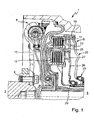
- FIG. 1 is a part of a drive train 1 of a motor vehicle shown.
- a drive unit 3 in particular an internal combustion engine, from which a crankshaft originates, and a transmission 5
- a wet-running double clutch 6 is arranged in lamellar construction.
- a torsional vibration damping device 8 is connected between the drive unit 3 and the dual clutch 6, a torsional vibration damping device 8 is connected.
- the torsional vibration damping device 8 is a dual-mass flywheel.
- the crankshaft of the internal combustion engine 3 is connected via screw 9 fixed to an input part 10 of the torsional vibration damping device 8.
- the structure and function of the torsional vibration damping device 8 and the dual clutch 6 are assumed to be known and therefore not explained in detail.
- the dual clutch 6 comprises a first multi-disc clutch assembly 11 and a second multi-disc clutch 12, which is arranged radially inside the first multi-disc clutch assembly 11.
- the first multi-disc clutch assembly 11 includes an outer disc carrier 15. At the end of the outer disc carrier 15 facing away from the drive unit 3, a lever spring element 20 is pivotally mounted. The lever spring element 20 is supported on a support element 21. Radial inside, an actuating bearing 23 engages on the lever spring element 20.
- the second multi-disc clutch assembly 12 includes an outer disc carrier 25 on which a further lever spring element 26 is pivotally mounted. The lever spring element 26 is supported on a support element 27. Radial inside engages the lever spring element 26, a further actuating bearing 29.
- the two actuating bearings 23 and 29 serve in a known manner to actuate the multi-plate clutch assemblies 11 and 12.
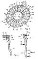
- the lever spring element 20 is shown in perspective.
- the lever spring element 20 comprises an annular base body 40, of which a total of eighteen spring tongues 41 to 45 extend radially inwardly, of which, however, only five are provided with reference numerals.
- the spring tongues 41 to 45 are the same length, but have different widths. In addition, the width, that is the extension of the spring tongues in the circumferential direction, decreases radially inwards.
- the lever spring element 20 is similar in construction to a plate spring and is therefore also referred to as a plate spring.
- lever arms 51 to 68 extend outwardly in the radial direction.
- the lever arms 51 which are also referred to as main tongues, each have a tooth 71, 72 radially on the outside.
- the teeth 71, 72 form a radial profiling radially outward on the lever spring element 20.
- the clamping tongue 81 is substantially U-shaped and has a base 85 from which two legs 86 and 87 extend.
- the leg 86 is integrally connected to the main tongue 52 and extends substantially in the circumferential direction.
- the base 85 extends substantially in the radial direction.
- the leg 86 extends substantially parallel to the leg 87 in the circumferential direction.
- a free end 88 of the clamping spring 81 is angled. The end 88 of the clamping spring 81 extends in the radial direction.
- the outer disk carrier 15 has a groove 89.
- the groove 89 is formed by a groove which extends in the circumferential direction and has a rectangular cross-section.
- the free end of the lever arm 51 is received in the groove or annular groove 89.
- the free end 88 of the clamping tongue 81 rests against the outer disk carrier 15 in an anti-rotation recess 90.
- FIG. 4 is indicated by arrows 91,92 and 94, 95, where which forces act.
- arrow 91 an inner clamping force is indicated.
- arrow 92 the sum of the clamping force and an engagement force is indicated.
- arrow 94 a lining force is indicated.
- the lining force 94 is equal to zero. Touch point means the point when clutch actuation at which the clearance is overcome and the lamella pads or the clutch disc with the friction partners are in contact for the first time.
- the lever spring element 20 is equipped with a self-clamping.
- the lining force for torque transmission can be built up in the disk pack.
- the outer main tongues of the lever spring element are supported in the annular groove 89 of the outer disk carrier 15.
- the outer disk carrier 15 essentially has the shape of a circular cylinder jacket 100, which is provided with an outer toothing 101 and an inner toothing 102.
- the outer disk carrier 15 has a substantially cuboid recess 104 with a bottom 105.
- dashed lines at 108 that the free end 88 of the clamping tongue 81 initially bears against the bottom 105 of the recess 104.
- the groove 110 represents the anti-rotation recess, which in FIG. 3 designated 90.
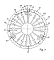
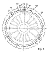
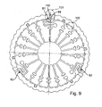
- FIGS. 7 to 9 the order of assembly of the lever spring element 20 in the outer disk carrier 15 is shown.
- the lever spring element 20, which is also referred to as a plate spring, in the outer disk carrier 15, which is also referred to as a plate carrier, inserted as in FIG. 7 is shown.
- the outer main tongues or lever arms 51 to 68 of the plate spring 20 in the axial direction as far against the clamping force of the clamping tongues 81 to 83 moves until the teeth on the outer edge of the main tongues in the region of the groove or annular groove (89 in FIG. 3 ) are arranged or face this.
- the plate spring 20 is rotated with the same tool 120 by half a pitch of the internal teeth 102 of the outer disk carrier 15, so that the teeth of the lever arms or main tongues in the annular groove and thus in the mountain of the internal teeth 102 of the disk carrier 15 are as in FIG. 9 can be seen at the point 132.
- the clamping tongues 81 to 83 engage with their free end 88 in the associated groove in the plate carrier 15, as at 131 in FIG. 9 you can see.
- the invention provides a mechanical clamping principle of the lever spring element, can be dispensed with in the conventional additional components.
- the lever arms and the clamping spring tongues are braced against each other during axial mounting. By locking the ends of the clamping tongues a reverse rotation and release of the clamping is prevented. At the same time, an edge centering takes place.
- the individual spring elements of the lever spring element 20 have a voltage-optimized geometry.
Landscapes
- Engineering & Computer Science (AREA)
- General Engineering & Computer Science (AREA)
- Mechanical Engineering (AREA)
- Mechanical Operated Clutches (AREA)
Abstract
Claims (10)
- Palier pivotant pour un élément ressort de levier de type ressort à disques (20), comprenant un corps de base (40) de type bague, depuis lequel s'étendent radialement vers l'extérieur des bras de levier (51-68) qui s'appuient avec leurs extrémités extérieures contre un dispositif de support (15), caractérisé en ce que les bras de levier (51-68) présentent à leurs extrémités extérieures un profilage radial (71, 72) qui coopère avec un profilage conjugué (102) sur le dispositif de support (15), le profilage conjugué (102) étant interrompu au niveau du dispositif de support (15) dans la direction axiale par une rainure (89) s'étendant dans la direction périphérique.
- Palier pivotant selon la revendication 1, caractérisé en ce que le profilage (71, 72) est formé par une denture extérieure.
- Palier pivotant selon l'une quelconque des revendications précédentes, caractérisé en ce que le profilage conjugué (102) est formé par une denture interne.
- Palier pivotant selon la revendication 3, caractérisé en ce qu'au moins une dent (71, 72) est réalisée à chaque fois sur les bras de levier (51-68), laquelle est configurée de manière complémentaire de la denture interne (102) du dispositif de support (15).
- Palier pivotant selon l'une quelconque des revendications précédentes, caractérisé en ce qu'au moins une langue de serrage élastique (81-83) part du corps de base (40) avec une extrémité (88) qui vient en prise dans un renfoncement de fixation en rotation (90) qui est prévu sur le dispositif de support (15).
- Palier pivotant selon la revendication 5, caractérisé en ce que l'extrémité (88) de la langue de serrage (81) s'étend dans la direction radiale vers l'extérieur au-delà de la périphérie extérieure du profilage (71, 72) sur l'élément ressort de levier (20).
- Palier pivotant selon la revendication 5 ou 6, caractérisé en ce que le renfoncement de fixation en rotation (90) est formé par une rainure (110) qui s'étend dans la direction radiale.
- Palier pivotant selon l'une quelconque des revendications 5 à 7, caractérisé en ce que plusieurs langues de serrage (81-83) sont serrées contre les bras de levier (51-68).
- Palier pivotant selon l'une quelconque des revendications précédentes, caractérisé en ce que plusieurs langues de ressort (41-45) s'étendent radialement vers l'intérieur depuis le corps de base de type bague (40).
- Dispositif d'embrayage comprenant au moins un dispositif de support (15, 25), sur lequel est monté de manière pivotante un élément ressort de levier (20, 26) de type ressort à disques, à l'aide d'un palier pivotant selon l'une quelconque des revendications précédentes.
Applications Claiming Priority (2)
| Application Number | Priority Date | Filing Date | Title |
|---|---|---|---|
| DE102005060593 | 2005-12-17 | ||
| PCT/DE2006/002100 WO2007073710A1 (fr) | 2005-12-17 | 2006-11-29 | Palier pivotant annulaire utilise dans un element ressort de levier de type ressort a disques et dispositif de couplage |
Publications (2)
| Publication Number | Publication Date |
|---|---|
| EP1966501A1 EP1966501A1 (fr) | 2008-09-10 |
| EP1966501B1 true EP1966501B1 (fr) | 2012-06-27 |
Family
ID=37814119
Family Applications (1)
| Application Number | Title | Priority Date | Filing Date |
|---|---|---|---|
| EP06828561A Not-in-force EP1966501B1 (fr) | 2005-12-17 | 2006-11-29 | Palier pivotant annulaire utilise dans un element ressort de levier de type ressort a disques et dispositif de couplage |
Country Status (4)
| Country | Link |
|---|---|
| EP (1) | EP1966501B1 (fr) |
| CN (1) | CN101331336B (fr) |
| DE (1) | DE112006003133A5 (fr) |
| WO (1) | WO2007073710A1 (fr) |
Families Citing this family (5)
| Publication number | Priority date | Publication date | Assignee | Title |
|---|---|---|---|---|
| US9568100B2 (en) * | 2012-04-26 | 2017-02-14 | Schaeffler Technologies AG & Co. KG | Transmission piston with retained release spring |
| IN2015DN02574A (fr) * | 2012-12-14 | 2015-09-11 | Schaeffler Technologies Ag | |
| DE102016217211A1 (de) * | 2015-09-16 | 2017-03-16 | Schaeffler Technologies AG & Co. KG | Kupplungssystem |
| DE102016214021B4 (de) * | 2016-07-29 | 2024-10-17 | Schaeffler Technologies AG & Co. KG | Kupplungseinrichtung |
| TR201615998A2 (tr) * | 2016-11-08 | 2018-05-21 | Ford Otomotiv Sanayi As | Bi̇r bağlanti aparati |
Family Cites Families (3)
| Publication number | Priority date | Publication date | Assignee | Title |
|---|---|---|---|---|
| JPS6040823A (ja) * | 1983-08-17 | 1985-03-04 | Daikin Mfg Co Ltd | クラツチカバ−組立体 |
| JP2005201372A (ja) * | 2004-01-15 | 2005-07-28 | Toyota Motor Corp | 摩擦係合装置 |
| EP1568905B1 (fr) * | 2004-02-24 | 2007-05-30 | LuK Lamellen und Kupplungsbau Beteiligungs KG | Embrayage à réglage automatique |
-
2006
- 2006-11-29 WO PCT/DE2006/002100 patent/WO2007073710A1/fr not_active Ceased
- 2006-11-29 CN CN2006800475841A patent/CN101331336B/zh not_active Expired - Fee Related
- 2006-11-29 DE DE112006003133T patent/DE112006003133A5/de not_active Withdrawn
- 2006-11-29 EP EP06828561A patent/EP1966501B1/fr not_active Not-in-force
Also Published As
| Publication number | Publication date |
|---|---|
| DE112006003133A5 (de) | 2008-09-11 |
| WO2007073710A1 (fr) | 2007-07-05 |
| CN101331336B (zh) | 2010-09-29 |
| EP1966501A1 (fr) | 2008-09-10 |
| CN101331336A (zh) | 2008-12-24 |
Similar Documents
| Publication | Publication Date | Title |
|---|---|---|
| DE112011101227B4 (de) | Doppelkupplung | |
| DE102008053377B4 (de) | Rupftilger | |
| DE112009002075B4 (de) | Schwungradanordnung | |
| EP2672140A2 (fr) | Agencement d'amortissement de vibrations de torsion, notamment d'un disque d'embrayage | |
| EP1693588B1 (fr) | Arrangement pour le support axial de deux éléments rotatifs. | |
| EP2672139A2 (fr) | Agencement d'amortissement de vibrations de torsion, notamment d'un disque d'embrayage | |
| DE102021124462A1 (de) | Drehschwingungsdämpfer mit einem Drehmomentbegrenzer | |
| EP2795148A1 (fr) | Embrayage à friction | |
| EP1302687B1 (fr) | Dispositif à embrayages multiples | |
| EP1966501B1 (fr) | Palier pivotant annulaire utilise dans un element ressort de levier de type ressort a disques et dispositif de couplage | |
| DE102015112219A1 (de) | Sperrsynchronisationsbaugruppe eines Schaltgetriebes sowie Verfahren zum Schalten eines Schaltgetriebes mit einer solchen Sperrsynchronisationsbaugruppe | |
| EP1950438B1 (fr) | Système d'entraînement pour un véhicule | |
| DE102011003030A1 (de) | Kupplungsscheibe für eine Reibungskupplung eines Kraftfahrzeugs | |
| WO2016169561A1 (fr) | Système d'embrayage | |
| DE10231513A1 (de) | Mehrfach-Kupplungsanordnung | |
| DE102011012896A1 (de) | Doppelkupplung | |
| WO2017194053A1 (fr) | Disque de friction pour amortisseur de disque d'embrayage | |
| DE102017130853A1 (de) | Kupplungseinrichtung | |
| DE19949362A1 (de) | Torsionsschwingungsdämpfer | |
| EP1460303A1 (fr) | Amortisseur de vibrations de torsion | |
| DE102019203844A1 (de) | Kupplungsscheibe | |
| DE102016216934A1 (de) | Anpressplatte für eine Reibungskupplung und Reibungskupplung | |
| DE3816890A1 (de) | Ausruecklagereinrichtung fuer eine gedrueckte kraftfahrzeugkupplung | |
| DE10248134A1 (de) | Torsionsschwingungsdämpfer mit einer Reibvorrichtung | |
| DE102011086969A1 (de) | Reibungskupplungseinrichtung |
Legal Events
| Date | Code | Title | Description |
|---|---|---|---|
| PUAI | Public reference made under article 153(3) epc to a published international application that has entered the european phase |
Free format text: ORIGINAL CODE: 0009012 |
|
| 17P | Request for examination filed |
Effective date: 20080717 |
|
| AK | Designated contracting states |
Kind code of ref document: A1 Designated state(s): AT BE BG CH CY CZ DE DK EE ES FI FR GB GR HU IE IS IT LI LT LU LV MC NL PL PT RO SE SI SK TR |
|
| 17Q | First examination report despatched |
Effective date: 20110128 |
|
| RAP1 | Party data changed (applicant data changed or rights of an application transferred) |
Owner name: SCHAEFFLER TECHNOLOGIES GMBH & CO. KG |
|
| GRAP | Despatch of communication of intention to grant a patent |
Free format text: ORIGINAL CODE: EPIDOSNIGR1 |
|
| RAP1 | Party data changed (applicant data changed or rights of an application transferred) |
Owner name: SCHAEFFLER TECHNOLOGIES AG & CO. KG |
|
| DAX | Request for extension of the european patent (deleted) | ||
| GRAS | Grant fee paid |
Free format text: ORIGINAL CODE: EPIDOSNIGR3 |
|
| GRAA | (expected) grant |
Free format text: ORIGINAL CODE: 0009210 |
|
| AK | Designated contracting states |
Kind code of ref document: B1 Designated state(s): AT BE BG CH CY CZ DE DK EE ES FI FR GB GR HU IE IS IT LI LT LU LV MC NL PL PT RO SE SI SK TR |
|
| REG | Reference to a national code |
Ref country code: GB Ref legal event code: FG4D Free format text: NOT ENGLISH |
|
| REG | Reference to a national code |
Ref country code: CH Ref legal event code: EP |
|
| REG | Reference to a national code |
Ref country code: AT Ref legal event code: REF Ref document number: 564411 Country of ref document: AT Kind code of ref document: T Effective date: 20120715 |
|
| REG | Reference to a national code |
Ref country code: IE Ref legal event code: FG4D Free format text: LANGUAGE OF EP DOCUMENT: GERMAN |
|
| REG | Reference to a national code |
Ref country code: DE Ref legal event code: R096 Ref document number: 502006011659 Country of ref document: DE Effective date: 20120823 |
|
| PG25 | Lapsed in a contracting state [announced via postgrant information from national office to epo] |
Ref country code: FI Free format text: LAPSE BECAUSE OF FAILURE TO SUBMIT A TRANSLATION OF THE DESCRIPTION OR TO PAY THE FEE WITHIN THE PRESCRIBED TIME-LIMIT Effective date: 20120627 Ref country code: LT Free format text: LAPSE BECAUSE OF FAILURE TO SUBMIT A TRANSLATION OF THE DESCRIPTION OR TO PAY THE FEE WITHIN THE PRESCRIBED TIME-LIMIT Effective date: 20120627 Ref country code: SE Free format text: LAPSE BECAUSE OF FAILURE TO SUBMIT A TRANSLATION OF THE DESCRIPTION OR TO PAY THE FEE WITHIN THE PRESCRIBED TIME-LIMIT Effective date: 20120627 |
|
| REG | Reference to a national code |
Ref country code: NL Ref legal event code: VDEP Effective date: 20120627 |
|
| REG | Reference to a national code |
Ref country code: LT Ref legal event code: MG4D Effective date: 20120606 |
|
| PG25 | Lapsed in a contracting state [announced via postgrant information from national office to epo] |
Ref country code: LV Free format text: LAPSE BECAUSE OF FAILURE TO SUBMIT A TRANSLATION OF THE DESCRIPTION OR TO PAY THE FEE WITHIN THE PRESCRIBED TIME-LIMIT Effective date: 20120627 Ref country code: SI Free format text: LAPSE BECAUSE OF FAILURE TO SUBMIT A TRANSLATION OF THE DESCRIPTION OR TO PAY THE FEE WITHIN THE PRESCRIBED TIME-LIMIT Effective date: 20120627 Ref country code: GR Free format text: LAPSE BECAUSE OF FAILURE TO SUBMIT A TRANSLATION OF THE DESCRIPTION OR TO PAY THE FEE WITHIN THE PRESCRIBED TIME-LIMIT Effective date: 20120928 |
|
| PG25 | Lapsed in a contracting state [announced via postgrant information from national office to epo] |
Ref country code: CY Free format text: LAPSE BECAUSE OF FAILURE TO SUBMIT A TRANSLATION OF THE DESCRIPTION OR TO PAY THE FEE WITHIN THE PRESCRIBED TIME-LIMIT Effective date: 20120627 Ref country code: SK Free format text: LAPSE BECAUSE OF FAILURE TO SUBMIT A TRANSLATION OF THE DESCRIPTION OR TO PAY THE FEE WITHIN THE PRESCRIBED TIME-LIMIT Effective date: 20120627 Ref country code: RO Free format text: LAPSE BECAUSE OF FAILURE TO SUBMIT A TRANSLATION OF THE DESCRIPTION OR TO PAY THE FEE WITHIN THE PRESCRIBED TIME-LIMIT Effective date: 20120627 Ref country code: EE Free format text: LAPSE BECAUSE OF FAILURE TO SUBMIT A TRANSLATION OF THE DESCRIPTION OR TO PAY THE FEE WITHIN THE PRESCRIBED TIME-LIMIT Effective date: 20120627 Ref country code: CZ Free format text: LAPSE BECAUSE OF FAILURE TO SUBMIT A TRANSLATION OF THE DESCRIPTION OR TO PAY THE FEE WITHIN THE PRESCRIBED TIME-LIMIT Effective date: 20120627 Ref country code: IS Free format text: LAPSE BECAUSE OF FAILURE TO SUBMIT A TRANSLATION OF THE DESCRIPTION OR TO PAY THE FEE WITHIN THE PRESCRIBED TIME-LIMIT Effective date: 20121027 |
|
| PG25 | Lapsed in a contracting state [announced via postgrant information from national office to epo] |
Ref country code: IT Free format text: LAPSE BECAUSE OF FAILURE TO SUBMIT A TRANSLATION OF THE DESCRIPTION OR TO PAY THE FEE WITHIN THE PRESCRIBED TIME-LIMIT Effective date: 20120627 Ref country code: PT Free format text: LAPSE BECAUSE OF FAILURE TO SUBMIT A TRANSLATION OF THE DESCRIPTION OR TO PAY THE FEE WITHIN THE PRESCRIBED TIME-LIMIT Effective date: 20121029 Ref country code: PL Free format text: LAPSE BECAUSE OF FAILURE TO SUBMIT A TRANSLATION OF THE DESCRIPTION OR TO PAY THE FEE WITHIN THE PRESCRIBED TIME-LIMIT Effective date: 20120627 |
|
| PG25 | Lapsed in a contracting state [announced via postgrant information from national office to epo] |
Ref country code: NL Free format text: LAPSE BECAUSE OF FAILURE TO SUBMIT A TRANSLATION OF THE DESCRIPTION OR TO PAY THE FEE WITHIN THE PRESCRIBED TIME-LIMIT Effective date: 20120627 |
|
| PG25 | Lapsed in a contracting state [announced via postgrant information from national office to epo] |
Ref country code: DK Free format text: LAPSE BECAUSE OF FAILURE TO SUBMIT A TRANSLATION OF THE DESCRIPTION OR TO PAY THE FEE WITHIN THE PRESCRIBED TIME-LIMIT Effective date: 20120627 Ref country code: ES Free format text: LAPSE BECAUSE OF FAILURE TO SUBMIT A TRANSLATION OF THE DESCRIPTION OR TO PAY THE FEE WITHIN THE PRESCRIBED TIME-LIMIT Effective date: 20121008 |
|
| PLBE | No opposition filed within time limit |
Free format text: ORIGINAL CODE: 0009261 |
|
| STAA | Information on the status of an ep patent application or granted ep patent |
Free format text: STATUS: NO OPPOSITION FILED WITHIN TIME LIMIT |
|
| BERE | Be: lapsed |
Owner name: SCHAEFFLER TECHNOLOGIES A.G. & CO. KG Effective date: 20121130 |
|
| 26N | No opposition filed |
Effective date: 20130328 |
|
| REG | Reference to a national code |
Ref country code: CH Ref legal event code: PL |
|
| GBPC | Gb: european patent ceased through non-payment of renewal fee |
Effective date: 20121129 |
|
| REG | Reference to a national code |
Ref country code: DE Ref legal event code: R097 Ref document number: 502006011659 Country of ref document: DE Effective date: 20130328 |
|
| PG25 | Lapsed in a contracting state [announced via postgrant information from national office to epo] |
Ref country code: LI Free format text: LAPSE BECAUSE OF NON-PAYMENT OF DUE FEES Effective date: 20121130 Ref country code: BG Free format text: LAPSE BECAUSE OF FAILURE TO SUBMIT A TRANSLATION OF THE DESCRIPTION OR TO PAY THE FEE WITHIN THE PRESCRIBED TIME-LIMIT Effective date: 20120927 Ref country code: CH Free format text: LAPSE BECAUSE OF NON-PAYMENT OF DUE FEES Effective date: 20121130 |
|
| REG | Reference to a national code |
Ref country code: IE Ref legal event code: MM4A |
|
| PG25 | Lapsed in a contracting state [announced via postgrant information from national office to epo] |
Ref country code: BE Free format text: LAPSE BECAUSE OF NON-PAYMENT OF DUE FEES Effective date: 20121130 |
|
| PG25 | Lapsed in a contracting state [announced via postgrant information from national office to epo] |
Ref country code: IE Free format text: LAPSE BECAUSE OF NON-PAYMENT OF DUE FEES Effective date: 20121129 |
|
| PG25 | Lapsed in a contracting state [announced via postgrant information from national office to epo] |
Ref country code: GB Free format text: LAPSE BECAUSE OF NON-PAYMENT OF DUE FEES Effective date: 20121129 |
|
| REG | Reference to a national code |
Ref country code: AT Ref legal event code: MM01 Ref document number: 564411 Country of ref document: AT Kind code of ref document: T Effective date: 20121130 |
|
| PG25 | Lapsed in a contracting state [announced via postgrant information from national office to epo] |
Ref country code: AT Free format text: LAPSE BECAUSE OF NON-PAYMENT OF DUE FEES Effective date: 20121130 |
|
| REG | Reference to a national code |
Ref country code: DE Ref legal event code: R081 Ref document number: 502006011659 Country of ref document: DE Owner name: SCHAEFFLER TECHNOLOGIES AG & CO. KG, DE Free format text: FORMER OWNER: SCHAEFFLER TECHNOLOGIES AG & CO. KG, 91074 HERZOGENAURACH, DE Effective date: 20140214 Ref country code: DE Ref legal event code: R081 Ref document number: 502006011659 Country of ref document: DE Owner name: SCHAEFFLER TECHNOLOGIES GMBH & CO. KG, DE Free format text: FORMER OWNER: SCHAEFFLER TECHNOLOGIES AG & CO. KG, 91074 HERZOGENAURACH, DE Effective date: 20140214 |
|
| PG25 | Lapsed in a contracting state [announced via postgrant information from national office to epo] |
Ref country code: TR Free format text: LAPSE BECAUSE OF FAILURE TO SUBMIT A TRANSLATION OF THE DESCRIPTION OR TO PAY THE FEE WITHIN THE PRESCRIBED TIME-LIMIT Effective date: 20120627 Ref country code: MC Free format text: LAPSE BECAUSE OF NON-PAYMENT OF DUE FEES Effective date: 20121130 |
|
| PG25 | Lapsed in a contracting state [announced via postgrant information from national office to epo] |
Ref country code: LU Free format text: LAPSE BECAUSE OF NON-PAYMENT OF DUE FEES Effective date: 20121129 |
|
| PG25 | Lapsed in a contracting state [announced via postgrant information from national office to epo] |
Ref country code: HU Free format text: LAPSE BECAUSE OF FAILURE TO SUBMIT A TRANSLATION OF THE DESCRIPTION OR TO PAY THE FEE WITHIN THE PRESCRIBED TIME-LIMIT Effective date: 20061129 |
|
| REG | Reference to a national code |
Ref country code: DE Ref legal event code: R081 Ref document number: 502006011659 Country of ref document: DE Owner name: SCHAEFFLER TECHNOLOGIES AG & CO. KG, DE Free format text: FORMER OWNER: SCHAEFFLER TECHNOLOGIES GMBH & CO. KG, 91074 HERZOGENAURACH, DE Effective date: 20150223 |
|
| REG | Reference to a national code |
Ref country code: FR Ref legal event code: PLFP Year of fee payment: 10 |
|
| REG | Reference to a national code |
Ref country code: FR Ref legal event code: PLFP Year of fee payment: 11 |
|
| REG | Reference to a national code |
Ref country code: FR Ref legal event code: PLFP Year of fee payment: 12 |
|
| PGFP | Annual fee paid to national office [announced via postgrant information from national office to epo] |
Ref country code: FR Payment date: 20171129 Year of fee payment: 12 |
|
| PGFP | Annual fee paid to national office [announced via postgrant information from national office to epo] |
Ref country code: DE Payment date: 20180131 Year of fee payment: 12 |
|
| REG | Reference to a national code |
Ref country code: DE Ref legal event code: R119 Ref document number: 502006011659 Country of ref document: DE |
|
| PG25 | Lapsed in a contracting state [announced via postgrant information from national office to epo] |
Ref country code: DE Free format text: LAPSE BECAUSE OF NON-PAYMENT OF DUE FEES Effective date: 20190601 Ref country code: FR Free format text: LAPSE BECAUSE OF NON-PAYMENT OF DUE FEES Effective date: 20181130 |
|
| P01 | Opt-out of the competence of the unified patent court (upc) registered |
Effective date: 20230523 |