EP1966503B1 - Manchon coulissant - Google Patents
Manchon coulissant Download PDFInfo
- Publication number
- EP1966503B1 EP1966503B1 EP06830093A EP06830093A EP1966503B1 EP 1966503 B1 EP1966503 B1 EP 1966503B1 EP 06830093 A EP06830093 A EP 06830093A EP 06830093 A EP06830093 A EP 06830093A EP 1966503 B1 EP1966503 B1 EP 1966503B1
- Authority
- EP
- European Patent Office
- Prior art keywords
- shift fork
- sliding sleeve
- rings
- sleeve body
- grooves
- Prior art date
- Legal status (The legal status is an assumption and is not a legal conclusion. Google has not performed a legal analysis and makes no representation as to the accuracy of the status listed.)
- Not-in-force
Links
- 238000000034 method Methods 0.000 claims description 11
- 229910052751 metal Inorganic materials 0.000 claims description 10
- 239000002184 metal Substances 0.000 claims description 10
- 238000005520 cutting process Methods 0.000 claims description 9
- 230000005540 biological transmission Effects 0.000 claims description 8
- 238000004519 manufacturing process Methods 0.000 claims description 7
- 238000003754 machining Methods 0.000 claims description 6
- 238000005096 rolling process Methods 0.000 claims description 3
- 238000003466 welding Methods 0.000 claims description 2
- 238000007493 shaping process Methods 0.000 claims 1
- 230000008878 coupling Effects 0.000 description 10
- 238000010168 coupling process Methods 0.000 description 10
- 238000005859 coupling reaction Methods 0.000 description 10
- 230000007935 neutral effect Effects 0.000 description 5
- 238000006073 displacement reaction Methods 0.000 description 4
- 239000000463 material Substances 0.000 description 3
- 230000006835 compression Effects 0.000 description 2
- 238000007906 compression Methods 0.000 description 2
- 238000005461 lubrication Methods 0.000 description 2
- 229910000831 Steel Inorganic materials 0.000 description 1
- 229910052782 aluminium Inorganic materials 0.000 description 1
- XAGFODPZIPBFFR-UHFFFAOYSA-N aluminium Chemical compound [Al] XAGFODPZIPBFFR-UHFFFAOYSA-N 0.000 description 1
- 238000000418 atomic force spectrum Methods 0.000 description 1
- 230000000903 blocking effect Effects 0.000 description 1
- 230000000694 effects Effects 0.000 description 1
- 238000004049 embossing Methods 0.000 description 1
- 238000005304 joining Methods 0.000 description 1
- 239000000314 lubricant Substances 0.000 description 1
- 230000013011 mating Effects 0.000 description 1
- 239000011295 pitch Substances 0.000 description 1
- 239000007858 starting material Substances 0.000 description 1
- 239000010959 steel Substances 0.000 description 1
Images


Classifications
-
- F—MECHANICAL ENGINEERING; LIGHTING; HEATING; WEAPONS; BLASTING
- F16—ENGINEERING ELEMENTS AND UNITS; GENERAL MEASURES FOR PRODUCING AND MAINTAINING EFFECTIVE FUNCTIONING OF MACHINES OR INSTALLATIONS; THERMAL INSULATION IN GENERAL
- F16D—COUPLINGS FOR TRANSMITTING ROTATION; CLUTCHES; BRAKES
- F16D23/00—Details of mechanically-actuated clutches not specific for one distinct type
- F16D23/02—Arrangements for synchronisation, also for power-operated clutches
- F16D23/04—Arrangements for synchronisation, also for power-operated clutches with an additional friction clutch
- F16D23/06—Arrangements for synchronisation, also for power-operated clutches with an additional friction clutch and a blocking mechanism preventing the engagement of the main clutch prior to synchronisation
- F16D2023/0631—Sliding sleeves; Details thereof
-
- F—MECHANICAL ENGINEERING; LIGHTING; HEATING; WEAPONS; BLASTING
- F16—ENGINEERING ELEMENTS AND UNITS; GENERAL MEASURES FOR PRODUCING AND MAINTAINING EFFECTIVE FUNCTIONING OF MACHINES OR INSTALLATIONS; THERMAL INSULATION IN GENERAL
- F16H—GEARING
- F16H63/00—Control outputs from the control unit to change-speed- or reversing-gearings for conveying rotary motion or to other devices than the final output mechanism
- F16H63/02—Final output mechanisms therefor; Actuating means for the final output mechanisms
- F16H63/30—Constructional features of the final output mechanisms
- F16H2063/3093—Final output elements, i.e. the final elements to establish gear ratio, e.g. coupling sleeves or other means establishing coupling to shaft
Definitions
- the invention relates to a sliding sleeve of a synchronizing unit for manual transmission with a sleeve body, which receives on its outer circumference a shift fork guide with a Weggabelnut and has on its inner circumference extending in the direction of the longitudinal central axis toothing.
- Such sliding sleeves are usually used as coupling elements in synchronizers manually switched motor vehicle transmission. They connect a gear shaft rotationally fixed with a rotatably mounted on the transmission shaft gear.
- the sliding sleeve is arranged concentrically to the transmission shaft, rotationally fixed and slidable in the longitudinal direction of the transmission shaft and coupled with a gear wheel on a synchronizer body.
- Sliding sleeves are available in various designs. In most cases, they have on their inner lateral surface on an inwardly facing toothing, which engages in a counter-toothing of the synchronizer body and in the switched state in a toothing of the gear wheel. On the outer circumference of the sliding sleeve a shift fork guide is provided. With the shift fork, the sliding sleeve is moved in the longitudinal direction on the synchronizer body until it is connected to the gear or moved back to its neutral position.
- the sliding sleeves are often held axially by a locking element which is received in the synchronizer body and usually spring-loaded acts on a recess.
- the recess is - depending on the design of the detent - on individual or all inwardly directed teeth of the sliding sleeve, the Riegelutzähnen formed.
- the locking element causes the sliding sleeve can only be moved axially after overcoming a defined resistance by the operator, when switching the gear, and does not move unintentionally and automatically in the axial direction.
- Rastogni z. B. set for a neutral and a detent position or to define displacement forces and force profiles of different heights are often two or more recesses in the longitudinal direction of the tooth arranged one behind the other.
- the plungers serve as an actuator for Vorsynchronmaschine. In axial displacement of the sliding sleeve, the plungers are taken through them. They initiate the process of synchronization by acting on arranged between the gear and the synchronizer synchronizer rings.
- the sliding sleeve In a gear change, the sliding sleeve is moved from the neutral position or from a second end position to a first end position, wherein the sliding sleeve via the pressure piece in a first movement step, the Ansynchronisation, an adjustment of the different speeds between the gear and the synchronizer body, initiates. Because the sliding sleeve absorbs forces in this process, it is required that it be guided safely through the shift fork.
- This shift fork guide is realized, for example, in that the sliding sleeve has on its outer circumference a circumferential Weghnelnut, in which engages a semicircular shift fork.
- each a circumferential paragraph is arranged.
- the mutually facing end faces form counter surfaces and the outer lateral surface of the sleeve body enclosed by them forms a circumferential shift fork groove which serves as a shift fork guide and in which a shift fork of the shift transmission engages.
- the mating surfaces are stops, via which the axial displacement movement is transmitted from the shift fork to the sliding sleeve.
- FIG. 1 of the FR 27 83 027 is disclosed a further sliding sleeve, which is integrally formed and directed to the shift fork has a Weggabelnut, for their production at their axial ends undercuts are provided.
- a sliding sleeve with a sheet metal toothing is for example in DE 101 22 184 A1 shown, wherein the sleeve body is externally bordered by two rings. The rings do not form a plane stop surface for the shift fork.
- the invention is therefore based on the object to provide a sliding sleeve, in which the aforementioned disadvantages are eliminated.
- this object is achieved according to the features of claim 1, characterized in that the grooves are arranged at least partially radially between the rings and the sleeve body.
- the shoulder or the groove are introduced in the case of machining production in the Heidelberggabelnut before the fine machining of the Weggabelnut takes place. They make it possible that the cutting edge of the turning tool during machining is not applied simultaneously to the main and secondary cutting plane, but only on one side. The load of the rotary tool and thus its wear are much lower.
- a shift fork guide which is arranged for example as an annular disc on the sleeve body to connect to the sleeve body switching fork groove side or both sides materially. This is particularly important in sliding sleeves with exposed roof tips of the teeth, because a cohesive attachment of separately manufactured shift fork guides from axially outside to inside, e.g. by welding due to lack of material is not possible.
- the groove according to the invention in the Heidelberggabelnut allows a fastening, which can now be done from axially inside to outside.
- the initial form of the non-machined sleeve body is in the form of a profiled sheet metal strip.
- the profiling includes all elements such as the internal teeth and their grooves, recesses, recesses and sloping roofs.
- the metal strip can, for. B. of an endless strip material having a length corresponding to the circumference of the sleeve body, are separated.
- the final cylindrical shape of the sleeve body is formed from this sheet metal strip, which is bent in a circle, brought together at its cutting edges and welded there.
- the shift fork guide can be introduced both before forming and subsequently be applied by separately manufactured components which are connected to the sleeve body.
- two grooves are formed in the Heidelberggabelnut, the grooves adjacent to the shift fork guide or partially between the shift fork guide and sleeve body are arranged.
- the shift fork guide on the outer circumference of the sleeve body is formed by two arranged on the outer circumference rings, which may also be formed as a disc. Both the Wenngabelnutground and the lateral walls of the shift fork guide forming parts of the rings according to the invention can each be individually processed without a tool must be engaged on several sides.
- the grooves fulfill another function to reduce the wear of a shift fork cooperating with the sliding sleeve.
- the shift fork does not extend or not fully into the grooves in the assembled state of the synchronizer.
- a sliding sleeve according to the invention can be produced particularly easily, by first in a first step in appropriately cut strip material, the grooves, the paragraph or any other outer diameter change are introduced. It is not important whether the introduction of the teeth occurs simultaneously, before or after. In a subsequent step, the band is then formed into an annular body, and the band ends are permanently fixed to each other. Optionally, then a finishing can be done.
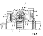
- FIG. 1 1 is a shaft of a manual transmission for motor vehicles, on which two gear wheels 2 and 3 are freely rotatably mounted. Between these two gear wheels 2 and 3, a synchronizer 4 is arranged, via which either one of the two gear wheels 2 or 3 can be coupled to the shaft 1. In this way, the gearbox is switched to different gear ratios.
- the synchronizing device 4 has a synchronizer body 5, which engages in rotation in a toothing 6 of the shaft. Furthermore, the synchronizer body 5 is provided on its outer circumference with an external toothing 7, in which teeth 8 of an internal toothing 45 of a sliding sleeve 9 engage. In the synchronizer body 5, a pressure piece 10 is further guided with a compression spring 11 which receives a spherical, in the longitudinal direction over the pressure piece 10 projecting locking element 12. The spherical detent element 12 protrudes from the synchronizer body 5 to approximately the tip circle of the external toothing 7.
- synchronizer rings 14 and 15 On both sides of the pressure piece 10 synchronizer rings 14 and 15 are arranged, the outside have a locking teeth 16 and 17 and inside a friction surface 18 and 19.
- the friction surfaces 18 and 19 of the synchronizer rings 14 and 15 cooperate with correspondingly formed friction surfaces 20 and 21 which are formed on the gear wheel 3 and a non-rotatably connected to the gear wheel coupling ring 22.
- an axial force is exerted on the respective synchronizer ring 14 or 15 during a corresponding locking synchronization via the pressure piece 10, during the initial synchronization, so that it exerts its friction surface 18 or 19 from the corresponding friction surface 20, 21 taken and rotated relative to the synchronizer body 5 by a certain angle.
- the locking teeth 16 blocks a further displacement of the sliding sleeve 9. This blocking effect is only canceled when a synchronization between the respective gear 2 and 3 and the shaft 1 is achieved.
- the internal toothing 8 of the sliding sleeve 9 is moved through the locking toothing 16 or 17 and finally reaches into engagement with a coupling toothing 23 or 24.
- the inner circumference of the sliding sleeve 9 has an internal toothing 45, the teeth 8, 8 ', viewed in cross section from the end face, taper in the direction of the transverse center plane of the sliding sleeve 9 so that centrally arranged on the transverse center plane recesses 34 to the Tooth flanks arise.
- These recesses 34 on the tooth flanks ensure that the teeth 8, 8 'of the sliding sleeve 9 and the coupling toothing of the coupling body or gear wheel, which are pushed into one another in a geared manner, do not separate from one another, in particular during load changes.
- the ends of the teeth 8, 8 'of sliding sleeves 9 are provided with roof slopes 32.
- the roof slopes 32 facilitate the engagement in the coupling teeth.
- the sliding sleeve 9 after FIG. 2 has a sleeve body 38 and two attached thereto rings 30, 31.
- the rings 30, 31 are integrally connected to the sleeve body 38 by welds 35 and form the shift fork guide 25. Together with the Wegzelnutground 36 lying between them outer periphery of the sliding sleeve 9 they limit the Heidelbergmülnut 26.
- the groove base 36 does not have the same distance d to the axis of rotation everywhere. Between the rings, at least one shoulder 29 or grooves 27, 28 are arranged.
- the grooves 27, 28 are circumferential and protrude below the rings 30, 31, so that a throat 39 is formed.
- both the mutually facing sides of the rings 30, 31 are processed without the machining tool in the region 40 of the Weggabelnutgrounds, which cooperates in the installed state with the shift fork, is applied. Also, the area 40, which cooperates with the shift fork in the installed state, can be processed without the tool comes into contact with the rings 30, 31.
- FIG. 3 shows a further not inventive sliding sleeve 9, in which the rooftops 33 of the teeth 8, 8 'with exemptions 37 are released.
- the sleeve body 38 is shown alone.
- the cohesive connection in the form of a weld 35 of the rings 30, 31 with the sleeve body 38 is not in the region of the exemptions 37, but adjacent to the grooves 27, 28.
- the outer ends 43, 44 of the grooves 27, 28 in this Embodiment lie in a plane with the inner walls 41, 42 of the rings 30, 31st
Landscapes
- Engineering & Computer Science (AREA)
- General Engineering & Computer Science (AREA)
- Mechanical Engineering (AREA)
- Mechanical Operated Clutches (AREA)
- Gear-Shifting Mechanisms (AREA)
Claims (9)
- Manchon coulissant d'une unité de synchronisation (4) pour boite de vitesses comprenant un corps de manchon (38) qui présente sur sa périphérie extérieure un guide de fourchette de changement de vitesse (25) avec une rainure de fourchette de changement de vitesse (26) et sur sa périphérie intérieure une denture intérieure (45) s'étendant dans la direction de l'axe médian longitudinal, le guide de fourchette de changement de vitesse (25) étant réalisé par deux bagues (30, 31) orientées parallèlement l'une à l'autre, qui sont fixées sur la périphérie extérieure du corps de manchon (38) et qui sont fabriquées séparément du corps de manchon (38), des rainures (27, 28) étant pratiquées dans le fond de rainure (36) de la rainure de la fourchette de changement de vitesse (26), lesquelles sont adjacentes aux bagues (30, 31), caractérisé en ce que les rainures (27, 28) sont disposées au moins partiellement radialement entre les bagues (30, 31) et le corps de manchon (38).
- Manchon coulissant selon la revendication 1, caractérisé en ce que le corps de manchon (38) se compose, dans son état de départ, d'une bande de tôle profilée au moins d'un côté, qui est cintrée en forme d'arc et dont les arêtes de coupe sont alors assemblées et soudées ensemble.
- Procédé de fabrication d'un manchon coulissant (9) selon la revendication 1, caractérisé en ce que- dans une première étape de procédé, des rainures (27, 28) ainsi qu'une denture (45) du côté arrière sont pratiquées dans une bande de tôle par gaufrage, laminage, roulage ou profilage,- en ce que dans une deuxième étape de procédé, la bande de tôle est façonnée pour former un corps de manchon annulaire (38), de sorte que la denture forme une denture intérieure (45) s'étendant dans la direction de l'axe médian longitudinal,- en ce qu'après le façonnage, un guide de fourchette de changement de vitesse (25) fabriqué séparément sur la périphérie extérieure du corps de manchon (38) est appliqué de telle sorte qu'il forme une rainure de fourchette de changement de vitesse (26) dans le fond de rainure (36) de laquelle sont pratiquées au moins partiellement les rainures (27, 28).
- Procédé selon la revendication 3, caractérisé en ce que le guide de fourchette de changement de vitesse (25) est formé par emmanchage par frettage ou par soudage entre des bagues (30, 31) disposées parallèlement l'une à l'autre.
- Procédé selon la revendication 4, caractérisé en ce que les bagues (30, 31) sont soudées dans la rainure de fourchette de changement de vitesse (26) de l'intérieur vers l'extérieur.
- Procédé selon la revendication 5, caractérisé en ce que la denture intérieure (45) présente des dents (8, 8') dont les pointes en forme de toit (33) sont exposées.
- Procédé selon la revendication 3, caractérisé en ce qu'après la deuxième étape de procédé, les extrémités de la bande sont fixées l'une à l'autre de manière durable.
- Procédé selon la revendication 4, caractérisé en ce qu'après l'application des bagues (30, 31), un post-usinage de la rainure de fourchette de changement de vitesse (26) a lieu au moyen d'un outil de tournage, qui s'applique uniquement contre l'arête de coupe principale.
- Unité de synchronisation comprenant un manchon coulissant selon la revendication 1 ou 2, ou comprenant un manchon coulissant fabriqué selon l'une quelconque des revendications 3 à 8.
Applications Claiming Priority (2)
| Application Number | Priority Date | Filing Date | Title |
|---|---|---|---|
| DE200510062171 DE102005062171A1 (de) | 2005-12-23 | 2005-12-23 | Schiebemuffe |
| PCT/EP2006/068812 WO2007074000A1 (fr) | 2005-12-23 | 2006-11-23 | Manchon coulissant |
Publications (2)
| Publication Number | Publication Date |
|---|---|
| EP1966503A1 EP1966503A1 (fr) | 2008-09-10 |
| EP1966503B1 true EP1966503B1 (fr) | 2012-09-26 |
Family
ID=37714550
Family Applications (1)
| Application Number | Title | Priority Date | Filing Date |
|---|---|---|---|
| EP06830093A Not-in-force EP1966503B1 (fr) | 2005-12-23 | 2006-11-23 | Manchon coulissant |
Country Status (3)
| Country | Link |
|---|---|
| EP (1) | EP1966503B1 (fr) |
| DE (1) | DE102005062171A1 (fr) |
| WO (1) | WO2007074000A1 (fr) |
Family Cites Families (12)
| Publication number | Priority date | Publication date | Assignee | Title |
|---|---|---|---|---|
| DE1822398U (de) * | 1960-09-13 | 1960-11-24 | Opel Adam Ag | Kupplungsverzahnung in zahnraederwechselgetrieben, insbesondere von kraftfahrzeugen. |
| JPS5566009A (en) * | 1978-11-08 | 1980-05-19 | Nissan Motor Co Ltd | Coupling sleeve |
| DE3908989A1 (de) * | 1989-03-18 | 1990-09-20 | Sinterstahl Gmbh | Verfahren zur herstellung einer schalt- oder schiebemuffe fuer kfz-getriebe |
| FR2783027B1 (fr) * | 1998-09-09 | 2000-10-13 | Renault | Synchroniseur de boite de vitesses manuelle |
| DE19851799A1 (de) * | 1998-11-09 | 2000-05-11 | Schaeffler Waelzlager Ohg | Schiebemuffe einer Synchronisiereinheit mit Reibkonus |
| DE10127140A1 (de) * | 2000-07-12 | 2002-02-07 | Schaeffler Waelzlager Ohg | Kupplungselement einer Kupplungseinheit für Schaltgetriebe |
| ITMI20011450A1 (it) * | 2000-07-12 | 2003-01-06 | Schaeffler Waelzlager Ohg | Elemento di accoppiamento di una unita' di accoppiamento per cambio di velocita' |
| DE10053031A1 (de) * | 2000-10-26 | 2002-05-08 | Ina Schaeffler Kg | Verzahnung |
| DE10122184A1 (de) * | 2001-05-08 | 2002-11-14 | Ina Schaeffler Kg | Verfahren zum Formen eines Abschnittes eines Zahnes einer Verzahnung mittels plastischer Verformung |
| DE10149845B4 (de) * | 2001-10-10 | 2009-01-15 | Schaeffler Kg | Grundkörper einer Schaltmuffe |
| DE10229911A1 (de) * | 2002-07-04 | 2004-01-15 | Ina-Schaeffler Kg | Schiebemuffe einer Schaltkupplung |
| JP2005201415A (ja) * | 2004-01-19 | 2005-07-28 | Nissan Diesel Motor Co Ltd | 変速機のシンクロナイザディテント構造 |
-
2005
- 2005-12-23 DE DE200510062171 patent/DE102005062171A1/de not_active Withdrawn
-
2006
- 2006-11-23 WO PCT/EP2006/068812 patent/WO2007074000A1/fr not_active Ceased
- 2006-11-23 EP EP06830093A patent/EP1966503B1/fr not_active Not-in-force
Also Published As
| Publication number | Publication date |
|---|---|
| WO2007074000A1 (fr) | 2007-07-05 |
| EP1966503A1 (fr) | 2008-09-10 |
| DE102005062171A1 (de) | 2007-06-28 |
Similar Documents
| Publication | Publication Date | Title |
|---|---|---|
| EP0955481B1 (fr) | Manchon de changement de vitesses d'un assemblage de synchronisation pour une boíte de vitesses | |
| EP2478243B1 (fr) | Bague de transmission pour un ensemble de synchronisation de boîte de vitesses | |
| EP1649196B1 (fr) | Porte-satellites pour boites de vitesses | |
| EP2092206B1 (fr) | Manchon coulissant d'un dispositif de synchronisation | |
| DE2510657A1 (de) | Zahnkupplung in zahnradwechselgetriebe mit stirnverzahnung und synchronisierung | |
| EP1192364B1 (fr) | Manchon coulissant d'une unite de synchronisation pour boites de vitesses | |
| EP1828647B1 (fr) | Systeme de changement de vitesses | |
| DE102008049978A1 (de) | Schalteinheit mit Kupplungskörper | |
| WO2008028784A1 (fr) | Corps synchrone | |
| EP1650457B1 (fr) | Système de changement de vitesse | |
| DE102006060535A1 (de) | Synchronisiereinrichtung für ein Schaltgetriebe | |
| DE102016204156B3 (de) | Schiebemuffe zum Schalten von Gangstufen eines Schaltgetriebes | |
| EP1966503B1 (fr) | Manchon coulissant | |
| DE102013221246A1 (de) | Synchronkörper | |
| DE3930173C1 (fr) | ||
| DE102007059843A1 (de) | Schiebemuffe für eine Schalteinrichtung und Verfahren zu deren Herstellung | |
| EP1146243B1 (fr) | Ensemble de sychronisation pour embrayage de changement de vitesses | |
| DE102015111802B4 (de) | Schaltzylinder für eine Schaltanordnung eines Kraftfahrzeuggetriebes | |
| DE102006061415A1 (de) | Synchronring einer Synchronisiereinrichtung | |
| WO2007074031A1 (fr) | Dispositif de synchronisation | |
| DE102018008500A1 (de) | Getriebe-Synchronisationseinrichtung | |
| DE102005061481A1 (de) | Schaltvorrichtung | |
| EP1365166B1 (fr) | Dispositif de transmission de couple | |
| DE102011075503A1 (de) | Synchronisiereinheit | |
| WO2014059985A1 (fr) | Dispositif de commutation pour boîte de vitesses |
Legal Events
| Date | Code | Title | Description |
|---|---|---|---|
| PUAI | Public reference made under article 153(3) epc to a published international application that has entered the european phase |
Free format text: ORIGINAL CODE: 0009012 |
|
| 17P | Request for examination filed |
Effective date: 20080723 |
|
| AK | Designated contracting states |
Kind code of ref document: A1 Designated state(s): AT BE BG CH CY CZ DE DK EE ES FI FR GB GR HU IE IS IT LI LT LU LV MC NL PL PT RO SE SI SK TR |
|
| 17Q | First examination report despatched |
Effective date: 20081120 |
|
| RAP1 | Party data changed (applicant data changed or rights of an application transferred) |
Owner name: SCHAEFFLER TECHNOLOGIES AG & CO. KG |
|
| GRAP | Despatch of communication of intention to grant a patent |
Free format text: ORIGINAL CODE: EPIDOSNIGR1 |
|
| DAX | Request for extension of the european patent (deleted) | ||
| GRAS | Grant fee paid |
Free format text: ORIGINAL CODE: EPIDOSNIGR3 |
|
| GRAA | (expected) grant |
Free format text: ORIGINAL CODE: 0009210 |
|
| AK | Designated contracting states |
Kind code of ref document: B1 Designated state(s): AT BE BG CH CY CZ DE DK EE ES FI FR GB GR HU IE IS IT LI LT LU LV MC NL PL PT RO SE SI SK TR |
|
| REG | Reference to a national code |
Ref country code: GB Ref legal event code: FG4D Free format text: NOT ENGLISH |
|
| REG | Reference to a national code |
Ref country code: CH Ref legal event code: EP |
|
| REG | Reference to a national code |
Ref country code: AT Ref legal event code: REF Ref document number: 577204 Country of ref document: AT Kind code of ref document: T Effective date: 20121015 |
|
| REG | Reference to a national code |
Ref country code: IE Ref legal event code: FG4D Free format text: LANGUAGE OF EP DOCUMENT: GERMAN |
|
| REG | Reference to a national code |
Ref country code: DE Ref legal event code: R096 Ref document number: 502006012024 Country of ref document: DE Effective date: 20121115 |
|
| PG25 | Lapsed in a contracting state [announced via postgrant information from national office to epo] |
Ref country code: FI Free format text: LAPSE BECAUSE OF FAILURE TO SUBMIT A TRANSLATION OF THE DESCRIPTION OR TO PAY THE FEE WITHIN THE PRESCRIBED TIME-LIMIT Effective date: 20120926 Ref country code: LT Free format text: LAPSE BECAUSE OF FAILURE TO SUBMIT A TRANSLATION OF THE DESCRIPTION OR TO PAY THE FEE WITHIN THE PRESCRIBED TIME-LIMIT Effective date: 20120926 |
|
| REG | Reference to a national code |
Ref country code: LT Ref legal event code: MG4D Effective date: 20120919 |
|
| REG | Reference to a national code |
Ref country code: NL Ref legal event code: VDEP Effective date: 20120926 |
|
| PG25 | Lapsed in a contracting state [announced via postgrant information from national office to epo] |
Ref country code: SI Free format text: LAPSE BECAUSE OF FAILURE TO SUBMIT A TRANSLATION OF THE DESCRIPTION OR TO PAY THE FEE WITHIN THE PRESCRIBED TIME-LIMIT Effective date: 20120926 Ref country code: SE Free format text: LAPSE BECAUSE OF FAILURE TO SUBMIT A TRANSLATION OF THE DESCRIPTION OR TO PAY THE FEE WITHIN THE PRESCRIBED TIME-LIMIT Effective date: 20120926 Ref country code: GR Free format text: LAPSE BECAUSE OF FAILURE TO SUBMIT A TRANSLATION OF THE DESCRIPTION OR TO PAY THE FEE WITHIN THE PRESCRIBED TIME-LIMIT Effective date: 20121227 Ref country code: LV Free format text: LAPSE BECAUSE OF FAILURE TO SUBMIT A TRANSLATION OF THE DESCRIPTION OR TO PAY THE FEE WITHIN THE PRESCRIBED TIME-LIMIT Effective date: 20120926 |
|
| PG25 | Lapsed in a contracting state [announced via postgrant information from national office to epo] |
Ref country code: CZ Free format text: LAPSE BECAUSE OF FAILURE TO SUBMIT A TRANSLATION OF THE DESCRIPTION OR TO PAY THE FEE WITHIN THE PRESCRIBED TIME-LIMIT Effective date: 20120926 Ref country code: RO Free format text: LAPSE BECAUSE OF FAILURE TO SUBMIT A TRANSLATION OF THE DESCRIPTION OR TO PAY THE FEE WITHIN THE PRESCRIBED TIME-LIMIT Effective date: 20120926 Ref country code: NL Free format text: LAPSE BECAUSE OF FAILURE TO SUBMIT A TRANSLATION OF THE DESCRIPTION OR TO PAY THE FEE WITHIN THE PRESCRIBED TIME-LIMIT Effective date: 20120926 Ref country code: EE Free format text: LAPSE BECAUSE OF FAILURE TO SUBMIT A TRANSLATION OF THE DESCRIPTION OR TO PAY THE FEE WITHIN THE PRESCRIBED TIME-LIMIT Effective date: 20120926 Ref country code: IS Free format text: LAPSE BECAUSE OF FAILURE TO SUBMIT A TRANSLATION OF THE DESCRIPTION OR TO PAY THE FEE WITHIN THE PRESCRIBED TIME-LIMIT Effective date: 20130126 Ref country code: ES Free format text: LAPSE BECAUSE OF FAILURE TO SUBMIT A TRANSLATION OF THE DESCRIPTION OR TO PAY THE FEE WITHIN THE PRESCRIBED TIME-LIMIT Effective date: 20130106 |
|
| BERE | Be: lapsed |
Owner name: SCHAEFFLER TECHNOLOGIES A.G. & CO. KG Effective date: 20121130 |
|
| PG25 | Lapsed in a contracting state [announced via postgrant information from national office to epo] |
Ref country code: PL Free format text: LAPSE BECAUSE OF FAILURE TO SUBMIT A TRANSLATION OF THE DESCRIPTION OR TO PAY THE FEE WITHIN THE PRESCRIBED TIME-LIMIT Effective date: 20120926 Ref country code: CY Free format text: LAPSE BECAUSE OF FAILURE TO SUBMIT A TRANSLATION OF THE DESCRIPTION OR TO PAY THE FEE WITHIN THE PRESCRIBED TIME-LIMIT Effective date: 20120926 Ref country code: PT Free format text: LAPSE BECAUSE OF FAILURE TO SUBMIT A TRANSLATION OF THE DESCRIPTION OR TO PAY THE FEE WITHIN THE PRESCRIBED TIME-LIMIT Effective date: 20130128 Ref country code: SK Free format text: LAPSE BECAUSE OF FAILURE TO SUBMIT A TRANSLATION OF THE DESCRIPTION OR TO PAY THE FEE WITHIN THE PRESCRIBED TIME-LIMIT Effective date: 20120926 |
|
| REG | Reference to a national code |
Ref country code: CH Ref legal event code: PL |
|
| PG25 | Lapsed in a contracting state [announced via postgrant information from national office to epo] |
Ref country code: LI Free format text: LAPSE BECAUSE OF NON-PAYMENT OF DUE FEES Effective date: 20121130 Ref country code: BG Free format text: LAPSE BECAUSE OF FAILURE TO SUBMIT A TRANSLATION OF THE DESCRIPTION OR TO PAY THE FEE WITHIN THE PRESCRIBED TIME-LIMIT Effective date: 20121226 Ref country code: DK Free format text: LAPSE BECAUSE OF FAILURE TO SUBMIT A TRANSLATION OF THE DESCRIPTION OR TO PAY THE FEE WITHIN THE PRESCRIBED TIME-LIMIT Effective date: 20120926 Ref country code: CH Free format text: LAPSE BECAUSE OF NON-PAYMENT OF DUE FEES Effective date: 20121130 |
|
| PLBE | No opposition filed within time limit |
Free format text: ORIGINAL CODE: 0009261 |
|
| STAA | Information on the status of an ep patent application or granted ep patent |
Free format text: STATUS: NO OPPOSITION FILED WITHIN TIME LIMIT |
|
| REG | Reference to a national code |
Ref country code: IE Ref legal event code: MM4A |
|
| REG | Reference to a national code |
Ref country code: FR Ref legal event code: ST Effective date: 20130731 |
|
| GBPC | Gb: european patent ceased through non-payment of renewal fee |
Effective date: 20121226 |
|
| PG25 | Lapsed in a contracting state [announced via postgrant information from national office to epo] |
Ref country code: IT Free format text: LAPSE BECAUSE OF FAILURE TO SUBMIT A TRANSLATION OF THE DESCRIPTION OR TO PAY THE FEE WITHIN THE PRESCRIBED TIME-LIMIT Effective date: 20120926 Ref country code: BE Free format text: LAPSE BECAUSE OF NON-PAYMENT OF DUE FEES Effective date: 20121130 |
|
| 26N | No opposition filed |
Effective date: 20130627 |
|
| REG | Reference to a national code |
Ref country code: DE Ref legal event code: R097 Ref document number: 502006012024 Country of ref document: DE Effective date: 20130627 |
|
| PG25 | Lapsed in a contracting state [announced via postgrant information from national office to epo] |
Ref country code: IE Free format text: LAPSE BECAUSE OF NON-PAYMENT OF DUE FEES Effective date: 20121123 |
|
| PG25 | Lapsed in a contracting state [announced via postgrant information from national office to epo] |
Ref country code: GB Free format text: LAPSE BECAUSE OF NON-PAYMENT OF DUE FEES Effective date: 20121226 Ref country code: FR Free format text: LAPSE BECAUSE OF NON-PAYMENT OF DUE FEES Effective date: 20121130 |
|
| REG | Reference to a national code |
Ref country code: AT Ref legal event code: MM01 Ref document number: 577204 Country of ref document: AT Kind code of ref document: T Effective date: 20121130 |
|
| PG25 | Lapsed in a contracting state [announced via postgrant information from national office to epo] |
Ref country code: AT Free format text: LAPSE BECAUSE OF NON-PAYMENT OF DUE FEES Effective date: 20121130 |
|
| REG | Reference to a national code |
Ref country code: DE Ref legal event code: R081 Ref document number: 502006012024 Country of ref document: DE Owner name: SCHAEFFLER TECHNOLOGIES GMBH & CO. KG, DE Free format text: FORMER OWNER: SCHAEFFLER TECHNOLOGIES AG & CO. KG, 91074 HERZOGENAURACH, DE Effective date: 20140212 Ref country code: DE Ref legal event code: R081 Ref document number: 502006012024 Country of ref document: DE Owner name: SCHAEFFLER TECHNOLOGIES AG & CO. KG, DE Free format text: FORMER OWNER: SCHAEFFLER TECHNOLOGIES AG & CO. KG, 91074 HERZOGENAURACH, DE Effective date: 20140212 |
|
| PG25 | Lapsed in a contracting state [announced via postgrant information from national office to epo] |
Ref country code: MC Free format text: LAPSE BECAUSE OF NON-PAYMENT OF DUE FEES Effective date: 20121130 Ref country code: TR Free format text: LAPSE BECAUSE OF FAILURE TO SUBMIT A TRANSLATION OF THE DESCRIPTION OR TO PAY THE FEE WITHIN THE PRESCRIBED TIME-LIMIT Effective date: 20120926 |
|
| PG25 | Lapsed in a contracting state [announced via postgrant information from national office to epo] |
Ref country code: LU Free format text: LAPSE BECAUSE OF NON-PAYMENT OF DUE FEES Effective date: 20121123 |
|
| PG25 | Lapsed in a contracting state [announced via postgrant information from national office to epo] |
Ref country code: HU Free format text: LAPSE BECAUSE OF FAILURE TO SUBMIT A TRANSLATION OF THE DESCRIPTION OR TO PAY THE FEE WITHIN THE PRESCRIBED TIME-LIMIT Effective date: 20061123 |
|
| REG | Reference to a national code |
Ref country code: DE Ref legal event code: R081 Ref document number: 502006012024 Country of ref document: DE Owner name: SCHAEFFLER TECHNOLOGIES AG & CO. KG, DE Free format text: FORMER OWNER: SCHAEFFLER TECHNOLOGIES GMBH & CO. KG, 91074 HERZOGENAURACH, DE Effective date: 20150123 |
|
| PGFP | Annual fee paid to national office [announced via postgrant information from national office to epo] |
Ref country code: DE Payment date: 20200130 Year of fee payment: 14 |
|
| REG | Reference to a national code |
Ref country code: DE Ref legal event code: R119 Ref document number: 502006012024 Country of ref document: DE |
|
| PG25 | Lapsed in a contracting state [announced via postgrant information from national office to epo] |
Ref country code: DE Free format text: LAPSE BECAUSE OF NON-PAYMENT OF DUE FEES Effective date: 20210601 |
|
| P01 | Opt-out of the competence of the unified patent court (upc) registered |
Effective date: 20230522 |