EP1365166B1 - Dispositif de transmission de couple - Google Patents
Dispositif de transmission de couple Download PDFInfo
- Publication number
- EP1365166B1 EP1365166B1 EP03009666A EP03009666A EP1365166B1 EP 1365166 B1 EP1365166 B1 EP 1365166B1 EP 03009666 A EP03009666 A EP 03009666A EP 03009666 A EP03009666 A EP 03009666A EP 1365166 B1 EP1365166 B1 EP 1365166B1
- Authority
- EP
- European Patent Office
- Prior art keywords
- toothed portions
- torque
- inner part
- toothed
- outer part
- Prior art date
- Legal status (The legal status is an assumption and is not a legal conclusion. Google has not performed a legal analysis and makes no representation as to the accuracy of the status listed.)
- Expired - Lifetime
Links
- 230000005540 biological transmission Effects 0.000 title description 13
- 230000002093 peripheral effect Effects 0.000 claims description 4
- 238000010276 construction Methods 0.000 claims 2
- 238000009434 installation Methods 0.000 description 3
- 238000011161 development Methods 0.000 description 2
- 230000018109 developmental process Effects 0.000 description 2
- 230000000295 complement effect Effects 0.000 description 1
- 238000001816 cooling Methods 0.000 description 1
- 230000003247 decreasing effect Effects 0.000 description 1
- 230000001419 dependent effect Effects 0.000 description 1
- 238000010438 heat treatment Methods 0.000 description 1
- 230000007935 neutral effect Effects 0.000 description 1
Images


Classifications
-
- F—MECHANICAL ENGINEERING; LIGHTING; HEATING; WEAPONS; BLASTING
- F16—ENGINEERING ELEMENTS AND UNITS; GENERAL MEASURES FOR PRODUCING AND MAINTAINING EFFECTIVE FUNCTIONING OF MACHINES OR INSTALLATIONS; THERMAL INSULATION IN GENERAL
- F16D—COUPLINGS FOR TRANSMITTING ROTATION; CLUTCHES; BRAKES
- F16D1/00—Couplings for rigidly connecting two coaxial shafts or other movable machine elements
- F16D1/10—Quick-acting couplings in which the parts are connected by simply bringing them together axially
- F16D1/108—Quick-acting couplings in which the parts are connected by simply bringing them together axially having retaining means rotating with the coupling and acting by interengaging parts, i.e. positive coupling
- F16D1/112—Quick-acting couplings in which the parts are connected by simply bringing them together axially having retaining means rotating with the coupling and acting by interengaging parts, i.e. positive coupling the interengaging parts comprising torque-transmitting surfaces, e.g. bayonet joints
-
- F—MECHANICAL ENGINEERING; LIGHTING; HEATING; WEAPONS; BLASTING
- F16—ENGINEERING ELEMENTS AND UNITS; GENERAL MEASURES FOR PRODUCING AND MAINTAINING EFFECTIVE FUNCTIONING OF MACHINES OR INSTALLATIONS; THERMAL INSULATION IN GENERAL
- F16D—COUPLINGS FOR TRANSMITTING ROTATION; CLUTCHES; BRAKES
- F16D23/00—Details of mechanically-actuated clutches not specific for one distinct type
- F16D23/02—Arrangements for synchronisation, also for power-operated clutches
- F16D23/04—Arrangements for synchronisation, also for power-operated clutches with an additional friction clutch
- F16D23/06—Arrangements for synchronisation, also for power-operated clutches with an additional friction clutch and a blocking mechanism preventing the engagement of the main clutch prior to synchronisation
-
- F—MECHANICAL ENGINEERING; LIGHTING; HEATING; WEAPONS; BLASTING
- F16—ENGINEERING ELEMENTS AND UNITS; GENERAL MEASURES FOR PRODUCING AND MAINTAINING EFFECTIVE FUNCTIONING OF MACHINES OR INSTALLATIONS; THERMAL INSULATION IN GENERAL
- F16D—COUPLINGS FOR TRANSMITTING ROTATION; CLUTCHES; BRAKES
- F16D23/00—Details of mechanically-actuated clutches not specific for one distinct type
- F16D23/02—Arrangements for synchronisation, also for power-operated clutches
- F16D23/04—Arrangements for synchronisation, also for power-operated clutches with an additional friction clutch
- F16D23/06—Arrangements for synchronisation, also for power-operated clutches with an additional friction clutch and a blocking mechanism preventing the engagement of the main clutch prior to synchronisation
- F16D2023/0637—Details relating to the hub member on which the sliding is arranged
Definitions
- the present invention relates to a torque transmission device according to the preamble of claim 1 and a transmission according to the preamble of claim 8.
- a torque transmission device is known from CH54543.
- CH 54543 describes a shaft / hub connection in which the shaft and the hub each have a spline-like profile. In the assembly position, outer circumferential surfaces of the "wave teeth” bear against inner peripheral surfaces of the "hub teeth”.
- a transmission in which a first and a second switchable gear are rotatably mounted on an input shaft.
- a fixed sleeve is arranged, which is connected in the axial direction and in the circumferential direction fixed to the input shaft.
- a sliding sleeve is arranged axially displaceable, which can assume three switching positions, namely a middle or neutral position and a first or second switching position in which the first and second ratchet via the sliding sleeve and the fixed sleeve rotatably connected to the shaft is.
- the fixed sleeve In such transmissions, the fixed sleeve usually has an internal toothing with teeth extending in the axial direction, which engages in a complementary toothing, which is provided on the shaft.
- the connection between the shaft and the fixed sleeve is usually a backlash-free Press fit.
- the installation of such a fixed sleeve is done either by applying a high axial force with which the "coverage" of the two components is overcome.
- the fixed sleeve can be heated and / or the shaft can be cooled, which makes it possible to join the two components without power or with a low axial force.
- Manual transmissions usually have a plurality of arranged on a single shaft shift sleeves.
- the inner diameters of the axially fixed successive sleeves are "stepped". "Graded” means that the inner diameter of the axially successive fixed sleeves from fixed sleeve to fixed sleeve increase so that they can be “threaded” as quickly as possible and without component damage on the provided on the shaft "Gegenvertechnikept" of the other not yet mounted fixed sleeves , Consequently, the inner diameter of the first to be mounted fixed sleeve is the largest and the last to be mounted fixed sleeve is smallest.
- the object of the invention is to provide a "torque transmission device" in general, in which the outer parts can be mounted on the inner parts with little installation effort in the case of a plurality of "torque transmission devices" to be assigned axially one behind the other.
- the invention is based on a torque transmission device having an outer part, which is arranged in the mounted state on an inner part. On the outer circumference of the inner part and on the inner circumference of Outer part, one or more toothing portions are each provided, which engage in the assembled state.
- the basic principle of the invention consists in providing at least one toothless section on the outer circumference of the inner part and on the inner circumference of the outer part, wherein the toothless sections are dimensioned such that in a mounting position of the outer and inner parts their toothing sections in the toothless sections of the respective other Part are receivable.
- the main advantage of the invention is that the outer part can be pushed in the mounting position substantially powerless axially over the inner part.
- the inner parts and the outer parts which have the function of fixed sleeves, can be of identical design and therefore cost-effective.
- a mounting is thus possible without difficulty even with identical fixed sleeves.
- the fixed joints, that is, the outer parts can be easily pushed over the inner parts, which are formed for example by external gears, which are provided on a shaft.
- the toothless sections of the outer part are seen to be longer in the circumferential direction than the toothed sections of the inner part to be introduced in the assembly position. Further, the inner radius of the toothless portions of the outer part is greater than the outer radius of the toothed portions of the inner part. Furthermore, the toothless portions of the inner part are longer in the circumferential direction than the toothed portions of the outer part and the outer radius of the toothless portions of the inner part is smaller than the inner radius of the toothed portions of the outer part. This geometric "conditions" ensures that the outer part in the mounting position is virtually force-free on the inner part pushed.
- the toothed portions of the inner part and the outer part are preferably dimensioned so that they form a play-free interference fit in the mounted state. By the interference fit an axial fixation of the outer part is ensured on the inner part.
- Figures 1 and 2 show a "torque transmission device" according to the prior art, which has an inner part and an outer part.
- the inner part is formed by a shaft 1 which has an outer toothing 2 extending over the entire outer circumference of the shaft 1.
- a fixed sleeve 3 is arranged in a press fit.
- the fixed sleeve 3 has an internal toothing 4, which engages in the external toothing 2.
- the fixed sleeve 3 in turn has an external toothing 5, in which an internal toothing 6 of a sliding sleeve 7 engages, which is axially displaceable on the fixed sleeve 3.
- FIG. 3 shows a shaft 8, on whose outer circumference four outer toothed sections 9 - 12 are provided, between each of which toothless sections 13-16 are provided whose radius is smaller than the "tip circle radius" of the toothed sections 9-12.
- Figure 4 shows an outer part, which is formed by a fixed sleeve 9 '.
- the fixed sleeve 9 ' has four internal gear sections 17-20, between each of which toothless sections 21-24 are provided.
- the radius of the toothless sections 21-24 is greater than the radius of the toothed sections 17-20.
- the fixed sleeve 9 has on its outer circumference a circumferential outer toothing 25, in which an associated internal toothing of an axially slidably mounted on the fixed sleeve 9 sliding sleeve 26 engages.
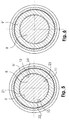
- Figure 5 shows the shaft 8 and the fixed sleeve 9 'in the assembled position.
- the toothing sections 9-12 of the shaft 8 are located in the toothless sections 21-24 of the fixed sleeve 9 '.
- the toothless sections 21-24 of the fixed sleeve 9 ' are slightly longer in the circumferential direction than the toothed sections 9-12 of the shaft 8.
- Figure 6 shows the assembled state.
- the toothed portions of the shaft 8 and the fixed sleeve 9 ' engage each other.
- the actual sliding of the fixed sleeve 9 'on the associated shaft teeth is then as mentioned above by a sufficiently high axial force with which the "excess” can be overcome and / or by heating or cooling of the "outer part” and possibly the “inner part” ,
Landscapes
- Engineering & Computer Science (AREA)
- General Engineering & Computer Science (AREA)
- Mechanical Engineering (AREA)
- Mechanical Operated Clutches (AREA)
Claims (10)
- Dispositif de transmission de couple avec une pièce extérieure (9'), qui à l'état monté est disposée sur une pièce intérieure (8), la périphérie extérieure de la pièce intérieure (8) et la périphérie intérieure de la pièce extérieure (9') présentant chacune au moins un segment denté (9 - 12, 17 - 20), et la périphérie extérieure de la pièce intérieure (8) et la périphérie intérieure de la pièce extérieure (9') présentant chacune au moins un segment sans dents (13 - 16, 20 - 24),
caractérisé en ce que
les segments dentés sont chaque fois formés par plusieurs dents et les segments dentés (9 - 12, 17 - 20) s'engagent les uns dans les autres à l'état monté, et les segments sans dents (13 - 16 ; 20 - 24) sont dimensionnés de telle manière que, dans une position de montage, les segments dentés (9 - 12 ; 17 - 20) puissent être logés dans les segments sans dents (13 - 16 ; 20 - 24) et que la pièce extérieure (9') puisse être glissée axialement au-dessus de la pièce intérieure (8) pratiquement sans effort. - Dispositif de transmission de couple selon la revendication 1,
caractérisé en ce que
la pièce extérieure (9') et la pièce intérieure (8) présentent chacune au moins deux segments dentés (9 - 12 ; 17 - 20), et un segment sans dents (13 - 16 ; 20 - 24) est chaque fois situé entre les segments dentés (9 - 12 ; 17 - 20). - Dispositif de transmission de couple selon la revendication 1 ou 2,
caractérisé en ce que
les segments sans dents (20 - 24) de la pièce extérieure (9') sont en direction périphérique, plus longs que les segments dentés (9 - 12) de la pièce intérieure (8) et le rayon intérieur des segments sans dents (20 - 24) de la pièce extérieure (9') est plus grand que le rayon extérieur des segments dentés (9 - 12) de la pièce intérieure (8), et les segments sans dents de la pièce intérieure (13 - 16) sont en direction périphérique plus longs que les segments dentés (17 - 20) de la pièce extérieure (9') et le rayon extérieur des segments sans dents (13 - 16) de la pièce intérieure (8) est plus petit que le rayon intérieur des segments dentés (17 - 20) de la pièce extérieure (9'). - Dispositif de transmission de couple selon l'une quelconque des revendications 1 à 3,
caractérisé en ce que
les segments dentés (9 - 12 ; 17 - 20) de la pièce intérieure (8) et de la pièce extérieure (9') sont dimensionnés de telle manière qu'à l'état monté, ils s'engagent les uns dans les autres en un ajustement serré sans jeu. - Dispositif de transmission de couple selon l'une quelconque des revendications 1 à 4,
caractérisé en ce que
la pièce intérieure (8) est un arbre et les segments dentés (9 - 12) de la pièce intérieure (8) sont formés directement sur l'arbre (8). - Dispositif de transmission de couple selon l'une quelconque des revendications 1 à 5,
caractérisé en ce que
la pièce extérieure (9') est un manchon fixe d'une boîte de vitesses, dans lequel le manchon fixe (9'), à l'état monté est solidaire de la pièce intérieure (8) en direction axiale et en direction périphérique, et sa périphérie extérieure présente une denture (25) avec des dents orientées en direction axiale. - Dispositif de transmission de couple selon la revendication 6,
caractérisé en ce qu'
un manchon glissant (26) pouvant coulisser axialement est disposé sur le manchon fixe (9'). - Boîte de vitesses avec un arbre de transmission (8),
caractérisée par
plusieurs dispositifs de transmission de couple selon l'une quelconque des revendications 1 à 7. - Boîte de vitesses selon la revendication 8,
caractérisée en ce que
les pièces intérieures prévues sur l'arbre de transmission ou formées par l'arbre de transmission (8) présentent la même structure. - Boîte de vitesses avec plusieurs étages de roues dentées, qui comprennent chaque fois un dispositif de transmission de couple selon l'une quelconque des revendications 1 à 7,
caractérisée en ce que
toutes les pièces intérieures des dispositifs de transmission de couple ont la même structure.
Applications Claiming Priority (2)
| Application Number | Priority Date | Filing Date | Title |
|---|---|---|---|
| DE2002123424 DE10223424A1 (de) | 2002-05-25 | 2002-05-25 | Drehmomentenübertragungseinrichtung |
| DE10223424 | 2002-05-25 |
Publications (2)
| Publication Number | Publication Date |
|---|---|
| EP1365166A1 EP1365166A1 (fr) | 2003-11-26 |
| EP1365166B1 true EP1365166B1 (fr) | 2007-06-13 |
Family
ID=29285703
Family Applications (1)
| Application Number | Title | Priority Date | Filing Date |
|---|---|---|---|
| EP03009666A Expired - Lifetime EP1365166B1 (fr) | 2002-05-25 | 2003-04-30 | Dispositif de transmission de couple |
Country Status (2)
| Country | Link |
|---|---|
| EP (1) | EP1365166B1 (fr) |
| DE (2) | DE10223424A1 (fr) |
Family Cites Families (7)
| Publication number | Priority date | Publication date | Assignee | Title |
|---|---|---|---|---|
| CH54543A (de) * | 1910-11-19 | 1912-06-01 | Joenkoepings Mek Werkstads | Vorrichtung zum Anbringen und Abnehmen von mit Naben versehenen Drehkörpern auf, bezw. von Wellen |
| FR2313593A1 (fr) * | 1975-06-05 | 1976-12-31 | Pitner Alfred | Assemblage avec un arbre d'un element tubulaire |
| DE3939274A1 (de) * | 1989-11-28 | 1991-05-29 | Getrag Getriebe Zahnrad | Synchronisiereinrichtung fuer ein schaltgetriebe |
| DE4008906A1 (de) * | 1990-03-20 | 1991-09-26 | Gkn Automotive Ag | Gebaute welle mit aufgesetzten antriebselementen und verfahren zur ihrer herstellung |
| US5269194A (en) * | 1992-05-28 | 1993-12-14 | Eaton Corporation | Transmission mainshaft thrust washer combination |
| DE4316233A1 (de) * | 1993-05-14 | 1994-11-17 | Zahnradfabrik Friedrichshafen | Halterung für ein Zahnrad |
| JPH08268295A (ja) * | 1995-03-31 | 1996-10-15 | Fuji Kiko Co Ltd | チルトステアリングコラムのアジャストストッパー |
-
2002
- 2002-05-25 DE DE2002123424 patent/DE10223424A1/de not_active Withdrawn
-
2003
- 2003-04-30 DE DE50307446T patent/DE50307446D1/de not_active Expired - Lifetime
- 2003-04-30 EP EP03009666A patent/EP1365166B1/fr not_active Expired - Lifetime
Non-Patent Citations (1)
| Title |
|---|
| None * |
Also Published As
| Publication number | Publication date |
|---|---|
| EP1365166A1 (fr) | 2003-11-26 |
| DE50307446D1 (de) | 2007-07-26 |
| DE10223424A1 (de) | 2003-12-04 |
Similar Documents
| Publication | Publication Date | Title |
|---|---|---|
| EP2478243B1 (fr) | Bague de transmission pour un ensemble de synchronisation de boîte de vitesses | |
| WO2010000590A1 (fr) | Dispositif de commande pour une boîte de vitesses de véhicule à moteur | |
| DE102007051741B4 (de) | Vorrichtung mit einer Schiebemuffe zum Schalten von Gangstufen eines Schaltgetriebes | |
| DE10004419A1 (de) | Meßvorrichtung für eine angestellte Kegelrollenlagerung und Verfahren zur Herstellung einer angestellten Kegelrollenlagerung | |
| EP3339682A1 (fr) | Pignon baladeur pour un dispositif de boîte à pignons baladeurs | |
| DE60106462T2 (de) | Synchronisierungseinrichtung in einem Fahrzeuggetriebe | |
| WO2006084659A1 (fr) | Systeme de changement de vitesses | |
| EP0683873B1 (fr) | Boite de vitesses a engrenages | |
| DE102005000886B4 (de) | Getriebeeinrichtung und Betätigungsvorrichtung zum Betätigen eines Getriebes, insbesondere Kraftfahrzeuggetriebes | |
| AT503895A2 (de) | Schiebemuffe | |
| EP1365166B1 (fr) | Dispositif de transmission de couple | |
| DE102007030507A1 (de) | Schiebemuffe | |
| DE102016204156B3 (de) | Schiebemuffe zum Schalten von Gangstufen eines Schaltgetriebes | |
| DE102017203584B4 (de) | Ziehkeilgetriebe, Wellenanordnung für ein Ziehkeilgetriebe, Motor-Getriebe-Anordnung und Fahrzeug | |
| DE3225201A1 (de) | Synchronisiereinrichtung | |
| WO2016146336A1 (fr) | Transmission à double embrayage | |
| DE102022201484B4 (de) | Getriebevorrichtung für ein Kraftfahrzeug | |
| DE102017222605A1 (de) | Gebaute Nockenwelle, sowie Verfahren zur Herstellung einer gebauten Nockenwelle | |
| DE102018221419A1 (de) | Getriebe | |
| EP3724461B1 (fr) | Arbre à cames rapportées et son procédé de fabrication | |
| WO2007147705A1 (fr) | Agencement d'un axe de satellite dans un porte-satellites | |
| DE102007032695A1 (de) | Synchronkörper einer Synchronisiereinrichtung für Schaltgetriebe | |
| EP1966503B1 (fr) | Manchon coulissant | |
| DE102015015363A1 (de) | Getriebeelement für ein Getriebe eines Kraftwagens | |
| DE102024132944A1 (de) | Schiebemuffe |
Legal Events
| Date | Code | Title | Description |
|---|---|---|---|
| PUAI | Public reference made under article 153(3) epc to a published international application that has entered the european phase |
Free format text: ORIGINAL CODE: 0009012 |
|
| 17P | Request for examination filed |
Effective date: 20030708 |
|
| AK | Designated contracting states |
Kind code of ref document: A1 Designated state(s): AT BE BG CH CY CZ DE DK EE ES FI FR GB GR HU IE IT LI LU MC NL PT RO SE SI SK TR |
|
| AX | Request for extension of the european patent |
Extension state: AL LT LV MK |
|
| AKX | Designation fees paid |
Designated state(s): DE FR GB IT |
|
| 17Q | First examination report despatched |
Effective date: 20061027 |
|
| GRAP | Despatch of communication of intention to grant a patent |
Free format text: ORIGINAL CODE: EPIDOSNIGR1 |
|
| GRAS | Grant fee paid |
Free format text: ORIGINAL CODE: EPIDOSNIGR3 |
|
| GRAA | (expected) grant |
Free format text: ORIGINAL CODE: 0009210 |
|
| AK | Designated contracting states |
Kind code of ref document: B1 Designated state(s): DE FR GB IT |
|
| REG | Reference to a national code |
Ref country code: GB Ref legal event code: FG4D Free format text: NOT ENGLISH |
|
| GBT | Gb: translation of ep patent filed (gb section 77(6)(a)/1977) |
Effective date: 20070619 |
|
| REF | Corresponds to: |
Ref document number: 50307446 Country of ref document: DE Date of ref document: 20070726 Kind code of ref document: P |
|
| ET | Fr: translation filed | ||
| PLBE | No opposition filed within time limit |
Free format text: ORIGINAL CODE: 0009261 |
|
| STAA | Information on the status of an ep patent application or granted ep patent |
Free format text: STATUS: NO OPPOSITION FILED WITHIN TIME LIMIT |
|
| 26N | No opposition filed |
Effective date: 20080314 |
|
| REG | Reference to a national code |
Ref country code: FR Ref legal event code: PLFP Year of fee payment: 13 |
|
| PGFP | Annual fee paid to national office [announced via postgrant information from national office to epo] |
Ref country code: DE Payment date: 20150411 Year of fee payment: 13 Ref country code: GB Payment date: 20150430 Year of fee payment: 13 |
|
| PGFP | Annual fee paid to national office [announced via postgrant information from national office to epo] |
Ref country code: IT Payment date: 20150428 Year of fee payment: 13 Ref country code: FR Payment date: 20150430 Year of fee payment: 13 |
|
| REG | Reference to a national code |
Ref country code: DE Ref legal event code: R119 Ref document number: 50307446 Country of ref document: DE |
|
| GBPC | Gb: european patent ceased through non-payment of renewal fee |
Effective date: 20160430 |
|
| REG | Reference to a national code |
Ref country code: FR Ref legal event code: ST Effective date: 20161230 |
|
| PG25 | Lapsed in a contracting state [announced via postgrant information from national office to epo] |
Ref country code: FR Free format text: LAPSE BECAUSE OF NON-PAYMENT OF DUE FEES Effective date: 20160502 Ref country code: DE Free format text: LAPSE BECAUSE OF NON-PAYMENT OF DUE FEES Effective date: 20161101 Ref country code: GB Free format text: LAPSE BECAUSE OF NON-PAYMENT OF DUE FEES Effective date: 20160430 |
|
| PG25 | Lapsed in a contracting state [announced via postgrant information from national office to epo] |
Ref country code: IT Free format text: LAPSE BECAUSE OF NON-PAYMENT OF DUE FEES Effective date: 20160430 |