EP1966588B1 - Integration einer testanordnung in ein mikrofluidisches format - Google Patents
Integration einer testanordnung in ein mikrofluidisches format Download PDFInfo
- Publication number
- EP1966588B1 EP1966588B1 EP06848919.4A EP06848919A EP1966588B1 EP 1966588 B1 EP1966588 B1 EP 1966588B1 EP 06848919 A EP06848919 A EP 06848919A EP 1966588 B1 EP1966588 B1 EP 1966588B1
- Authority
- EP
- European Patent Office
- Prior art keywords
- channel
- blood
- blood sample
- light
- sample
- Prior art date
- Legal status (The legal status is an assumption and is not a legal conclusion. Google has not performed a legal analysis and makes no representation as to the accuracy of the status listed.)
- Ceased
Links
- 238000003556 assay Methods 0.000 title claims description 34
- 239000008280 blood Substances 0.000 claims description 162
- 210000004369 blood Anatomy 0.000 claims description 154
- 239000012530 fluid Substances 0.000 claims description 72
- 239000003153 chemical reaction reagent Substances 0.000 claims description 67
- 230000002934 lysing effect Effects 0.000 claims description 56
- 230000003287 optical effect Effects 0.000 claims description 42
- 239000002245 particle Substances 0.000 claims description 42
- 102000001554 Hemoglobins Human genes 0.000 claims description 39
- 108010054147 Hemoglobins Proteins 0.000 claims description 39
- 238000010521 absorption reaction Methods 0.000 claims description 23
- 239000000463 material Substances 0.000 claims description 19
- 239000004033 plastic Substances 0.000 claims description 17
- 229920003023 plastic Polymers 0.000 claims description 17
- 238000000034 method Methods 0.000 claims description 16
- 101000738771 Homo sapiens Receptor-type tyrosine-protein phosphatase C Proteins 0.000 claims description 11
- 102100037422 Receptor-type tyrosine-protein phosphatase C Human genes 0.000 claims description 11
- 239000011521 glass Substances 0.000 claims description 10
- 239000002699 waste material Substances 0.000 claims description 10
- 238000003018 immunoassay Methods 0.000 claims description 9
- 239000000843 powder Substances 0.000 claims description 7
- 230000008021 deposition Effects 0.000 claims description 6
- 244000052769 pathogen Species 0.000 claims description 4
- 241000223960 Plasmodium falciparum Species 0.000 claims description 3
- 239000000470 constituent Substances 0.000 claims 6
- 240000009188 Phyllostachys vivax Species 0.000 claims 2
- 210000004027 cell Anatomy 0.000 description 144
- 239000000523 sample Substances 0.000 description 138
- 210000003743 erythrocyte Anatomy 0.000 description 79
- 210000000265 leukocyte Anatomy 0.000 description 76
- 238000005259 measurement Methods 0.000 description 55
- 201000004792 malaria Diseases 0.000 description 45
- 238000004458 analytical method Methods 0.000 description 38
- 238000013459 approach Methods 0.000 description 38
- 238000010586 diagram Methods 0.000 description 30
- 238000001514 detection method Methods 0.000 description 29
- 238000004163 cytometry Methods 0.000 description 27
- 208000030507 AIDS Diseases 0.000 description 22
- 210000001772 blood platelet Anatomy 0.000 description 21
- 238000012360 testing method Methods 0.000 description 20
- 210000004698 lymphocyte Anatomy 0.000 description 19
- 241000894007 species Species 0.000 description 19
- 239000000427 antigen Substances 0.000 description 15
- 238000004820 blood count Methods 0.000 description 14
- 238000012544 monitoring process Methods 0.000 description 14
- 239000003086 colorant Substances 0.000 description 13
- 238000003491 array Methods 0.000 description 12
- 102000036639 antigens Human genes 0.000 description 11
- 108091007433 antigens Proteins 0.000 description 11
- 230000004069 differentiation Effects 0.000 description 11
- 238000000684 flow cytometry Methods 0.000 description 11
- 239000003550 marker Substances 0.000 description 11
- 238000005086 pumping Methods 0.000 description 11
- 239000003795 chemical substances by application Substances 0.000 description 10
- 201000010099 disease Diseases 0.000 description 10
- 208000037265 diseases, disorders, signs and symptoms Diseases 0.000 description 10
- 230000008901 benefit Effects 0.000 description 9
- 230000000875 corresponding effect Effects 0.000 description 9
- 230000006870 function Effects 0.000 description 9
- 238000003860 storage Methods 0.000 description 9
- 230000015572 biosynthetic process Effects 0.000 description 8
- 210000000601 blood cell Anatomy 0.000 description 8
- 229920000089 Cyclic olefin copolymer Polymers 0.000 description 7
- 238000005534 hematocrit Methods 0.000 description 7
- 238000009652 hydrodynamic focusing Methods 0.000 description 7
- 230000008569 process Effects 0.000 description 7
- 238000011282 treatment Methods 0.000 description 7
- 201000008827 tuberculosis Diseases 0.000 description 7
- 239000004713 Cyclic olefin copolymer Substances 0.000 description 6
- 238000010790 dilution Methods 0.000 description 6
- 239000012895 dilution Substances 0.000 description 6
- 208000031886 HIV Infections Diseases 0.000 description 5
- 239000011324 bead Substances 0.000 description 5
- 230000000994 depressogenic effect Effects 0.000 description 5
- 238000003745 diagnosis Methods 0.000 description 5
- 239000007788 liquid Substances 0.000 description 5
- 230000007246 mechanism Effects 0.000 description 5
- 210000001616 monocyte Anatomy 0.000 description 5
- 210000000440 neutrophil Anatomy 0.000 description 5
- 238000002360 preparation method Methods 0.000 description 5
- 230000003612 virological effect Effects 0.000 description 5
- 241000193738 Bacillus anthracis Species 0.000 description 4
- 208000003322 Coinfection Diseases 0.000 description 4
- 208000037357 HIV infectious disease Diseases 0.000 description 4
- 239000003146 anticoagulant agent Substances 0.000 description 4
- 229940127219 anticoagulant drug Drugs 0.000 description 4
- 230000005540 biological transmission Effects 0.000 description 4
- 230000024245 cell differentiation Effects 0.000 description 4
- 230000008859 change Effects 0.000 description 4
- 238000009826 distribution Methods 0.000 description 4
- 229940079593 drug Drugs 0.000 description 4
- 239000003814 drug Substances 0.000 description 4
- 230000003760 hair shine Effects 0.000 description 4
- 208000033519 human immunodeficiency virus infectious disease Diseases 0.000 description 4
- 238000005286 illumination Methods 0.000 description 4
- 230000004044 response Effects 0.000 description 4
- 238000000926 separation method Methods 0.000 description 4
- 239000000758 substrate Substances 0.000 description 4
- 241000894006 Bacteria Species 0.000 description 3
- 241000224016 Plasmodium Species 0.000 description 3
- XUIMIQQOPSSXEZ-UHFFFAOYSA-N Silicon Chemical compound [Si] XUIMIQQOPSSXEZ-UHFFFAOYSA-N 0.000 description 3
- 230000009471 action Effects 0.000 description 3
- 238000000149 argon plasma sintering Methods 0.000 description 3
- 230000004888 barrier function Effects 0.000 description 3
- 210000004970 cd4 cell Anatomy 0.000 description 3
- 238000001914 filtration Methods 0.000 description 3
- 238000001917 fluorescence detection Methods 0.000 description 3
- 125000001153 fluoro group Chemical group F* 0.000 description 3
- 238000011534 incubation Methods 0.000 description 3
- 239000010410 layer Substances 0.000 description 3
- 238000004519 manufacturing process Methods 0.000 description 3
- 238000002156 mixing Methods 0.000 description 3
- 244000045947 parasite Species 0.000 description 3
- 229920000642 polymer Polymers 0.000 description 3
- 238000012545 processing Methods 0.000 description 3
- 239000010453 quartz Substances 0.000 description 3
- 230000009467 reduction Effects 0.000 description 3
- 230000035945 sensitivity Effects 0.000 description 3
- 229910052710 silicon Inorganic materials 0.000 description 3
- 239000010703 silicon Substances 0.000 description 3
- VYPSYNLAJGMNEJ-UHFFFAOYSA-N silicon dioxide Inorganic materials O=[Si]=O VYPSYNLAJGMNEJ-UHFFFAOYSA-N 0.000 description 3
- 239000000243 solution Substances 0.000 description 3
- 238000002560 therapeutic procedure Methods 0.000 description 3
- 239000010409 thin film Substances 0.000 description 3
- XLYOFNOQVPJJNP-UHFFFAOYSA-N water Substances O XLYOFNOQVPJJNP-UHFFFAOYSA-N 0.000 description 3
- 210000000707 wrist Anatomy 0.000 description 3
- 208000035473 Communicable disease Diseases 0.000 description 2
- 108010029961 Filgrastim Proteins 0.000 description 2
- 206010028980 Neoplasm Diseases 0.000 description 2
- 241000223810 Plasmodium vivax Species 0.000 description 2
- 210000001744 T-lymphocyte Anatomy 0.000 description 2
- 239000003124 biologic agent Substances 0.000 description 2
- 230000004071 biological effect Effects 0.000 description 2
- 239000010796 biological waste Substances 0.000 description 2
- 230000036770 blood supply Effects 0.000 description 2
- 238000004364 calculation method Methods 0.000 description 2
- 201000011510 cancer Diseases 0.000 description 2
- 238000006243 chemical reaction Methods 0.000 description 2
- 238000002512 chemotherapy Methods 0.000 description 2
- 238000010276 construction Methods 0.000 description 2
- 230000002596 correlated effect Effects 0.000 description 2
- 238000011161 development Methods 0.000 description 2
- 230000018109 developmental process Effects 0.000 description 2
- 238000001035 drying Methods 0.000 description 2
- 238000005516 engineering process Methods 0.000 description 2
- 239000010408 film Substances 0.000 description 2
- 230000009477 glass transition Effects 0.000 description 2
- 230000036541 health Effects 0.000 description 2
- 208000015181 infectious disease Diseases 0.000 description 2
- 230000010354 integration Effects 0.000 description 2
- 238000002372 labelling Methods 0.000 description 2
- 238000013508 migration Methods 0.000 description 2
- 230000005012 migration Effects 0.000 description 2
- 229940029345 neupogen Drugs 0.000 description 2
- 238000004806 packaging method and process Methods 0.000 description 2
- 230000010287 polarization Effects 0.000 description 2
- 238000007639 printing Methods 0.000 description 2
- 102000004169 proteins and genes Human genes 0.000 description 2
- 108090000623 proteins and genes Proteins 0.000 description 2
- 230000005180 public health Effects 0.000 description 2
- 239000012898 sample dilution Substances 0.000 description 2
- 238000012216 screening Methods 0.000 description 2
- 239000000126 substance Substances 0.000 description 2
- 210000003462 vein Anatomy 0.000 description 2
- 230000000007 visual effect Effects 0.000 description 2
- 235000012431 wafers Nutrition 0.000 description 2
- 102100024222 B-lymphocyte antigen CD19 Human genes 0.000 description 1
- 206010063094 Cerebral malaria Diseases 0.000 description 1
- 206010059866 Drug resistance Diseases 0.000 description 1
- 102100031573 Hematopoietic progenitor cell antigen CD34 Human genes 0.000 description 1
- 101000980825 Homo sapiens B-lymphocyte antigen CD19 Proteins 0.000 description 1
- 101000777663 Homo sapiens Hematopoietic progenitor cell antigen CD34 Proteins 0.000 description 1
- 101100220215 Lineus sanguineus CDX gene Proteins 0.000 description 1
- 206010025323 Lymphomas Diseases 0.000 description 1
- 241000282341 Mustela putorius furo Species 0.000 description 1
- 241000223821 Plasmodium malariae Species 0.000 description 1
- 241001505293 Plasmodium ovale Species 0.000 description 1
- 239000004793 Polystyrene Substances 0.000 description 1
- 206010036618 Premenstrual syndrome Diseases 0.000 description 1
- 241000700605 Viruses Species 0.000 description 1
- NIXOWILDQLNWCW-UHFFFAOYSA-N acrylic acid group Chemical group C(C=C)(=O)O NIXOWILDQLNWCW-UHFFFAOYSA-N 0.000 description 1
- 239000000853 adhesive Substances 0.000 description 1
- 230000001070 adhesive effect Effects 0.000 description 1
- 210000004712 air sac Anatomy 0.000 description 1
- 230000000798 anti-retroviral effect Effects 0.000 description 1
- 238000013096 assay test Methods 0.000 description 1
- QVGXLLKOCUKJST-UHFFFAOYSA-N atomic oxygen Chemical compound [O] QVGXLLKOCUKJST-UHFFFAOYSA-N 0.000 description 1
- 230000001580 bacterial effect Effects 0.000 description 1
- 229920006232 basofil Polymers 0.000 description 1
- 210000003651 basophil Anatomy 0.000 description 1
- 230000008033 biological extinction Effects 0.000 description 1
- 239000012472 biological sample Substances 0.000 description 1
- BJQHLKABXJIVAM-UHFFFAOYSA-N bis(2-ethylhexyl) phthalate Chemical compound CCCCC(CC)COC(=O)C1=CC=CC=C1C(=O)OCC(CC)CCCC BJQHLKABXJIVAM-UHFFFAOYSA-N 0.000 description 1
- 230000000903 blocking effect Effects 0.000 description 1
- 238000004159 blood analysis Methods 0.000 description 1
- 230000001364 causal effect Effects 0.000 description 1
- 238000004891 communication Methods 0.000 description 1
- 239000004020 conductor Substances 0.000 description 1
- 230000008878 coupling Effects 0.000 description 1
- 238000010168 coupling process Methods 0.000 description 1
- 238000005859 coupling reaction Methods 0.000 description 1
- 230000009089 cytolysis Effects 0.000 description 1
- 230000003247 decreasing effect Effects 0.000 description 1
- 230000007123 defense Effects 0.000 description 1
- 238000013461 design Methods 0.000 description 1
- 230000006866 deterioration Effects 0.000 description 1
- 238000009792 diffusion process Methods 0.000 description 1
- 239000003085 diluting agent Substances 0.000 description 1
- 230000003292 diminished effect Effects 0.000 description 1
- 239000000975 dye Substances 0.000 description 1
- 239000003792 electrolyte Substances 0.000 description 1
- 230000007613 environmental effect Effects 0.000 description 1
- 210000003979 eosinophil Anatomy 0.000 description 1
- 238000011156 evaluation Methods 0.000 description 1
- 238000009501 film coating Methods 0.000 description 1
- 238000002189 fluorescence spectrum Methods 0.000 description 1
- 239000007850 fluorescent dye Substances 0.000 description 1
- 235000013305 food Nutrition 0.000 description 1
- 238000004868 gas analysis Methods 0.000 description 1
- 210000003714 granulocyte Anatomy 0.000 description 1
- 230000001900 immune effect Effects 0.000 description 1
- 210000000987 immune system Anatomy 0.000 description 1
- 238000013394 immunophenotyping Methods 0.000 description 1
- 239000004615 ingredient Substances 0.000 description 1
- 238000003780 insertion Methods 0.000 description 1
- 230000037431 insertion Effects 0.000 description 1
- 238000002955 isolation Methods 0.000 description 1
- 239000002650 laminated plastic Substances 0.000 description 1
- 238000003475 lamination Methods 0.000 description 1
- 208000032839 leukemia Diseases 0.000 description 1
- 239000006193 liquid solution Substances 0.000 description 1
- 238000012423 maintenance Methods 0.000 description 1
- 239000000203 mixture Substances 0.000 description 1
- 238000012986 modification Methods 0.000 description 1
- 230000004048 modification Effects 0.000 description 1
- 239000002991 molded plastic Substances 0.000 description 1
- 230000000877 morphologic effect Effects 0.000 description 1
- 238000000465 moulding Methods 0.000 description 1
- 230000003039 myelosuppressive effect Effects 0.000 description 1
- 230000003204 osmotic effect Effects 0.000 description 1
- 239000001301 oxygen Substances 0.000 description 1
- 229910052760 oxygen Inorganic materials 0.000 description 1
- 230000008506 pathogenesis Effects 0.000 description 1
- 239000004038 photonic crystal Substances 0.000 description 1
- 229940118768 plasmodium malariae Drugs 0.000 description 1
- 239000002985 plastic film Substances 0.000 description 1
- 229920006255 plastic film Polymers 0.000 description 1
- 239000004417 polycarbonate Substances 0.000 description 1
- 229920000515 polycarbonate Polymers 0.000 description 1
- 229920002223 polystyrene Polymers 0.000 description 1
- 238000004094 preconcentration Methods 0.000 description 1
- 230000002265 prevention Effects 0.000 description 1
- 230000003449 preventive effect Effects 0.000 description 1
- 230000000750 progressive effect Effects 0.000 description 1
- 238000011321 prophylaxis Methods 0.000 description 1
- 244000000040 protozoan parasite Species 0.000 description 1
- 238000012163 sequencing technique Methods 0.000 description 1
- 239000002356 single layer Substances 0.000 description 1
- 238000010186 staining Methods 0.000 description 1
- 208000024891 symptom Diseases 0.000 description 1
- 208000011580 syndromic disease Diseases 0.000 description 1
- 230000009897 systematic effect Effects 0.000 description 1
- 238000010998 test method Methods 0.000 description 1
- 238000012549 training Methods 0.000 description 1
- 238000013519 translation Methods 0.000 description 1
- 238000011269 treatment regimen Methods 0.000 description 1
- 238000002562 urinalysis Methods 0.000 description 1
Images





















Classifications
-
- G—PHYSICS
- G01—MEASURING; TESTING
- G01N—INVESTIGATING OR ANALYSING MATERIALS BY DETERMINING THEIR CHEMICAL OR PHYSICAL PROPERTIES
- G01N15/00—Investigating characteristics of particles; Investigating permeability, pore-volume or surface-area of porous materials
- G01N15/10—Investigating individual particles
- G01N15/14—Optical investigation techniques, e.g. flow cytometry
- G01N15/1456—Optical investigation techniques, e.g. flow cytometry without spatial resolution of the texture or inner structure of the particle, e.g. processing of pulse signals
- G01N15/1459—Optical investigation techniques, e.g. flow cytometry without spatial resolution of the texture or inner structure of the particle, e.g. processing of pulse signals the analysis being performed on a sample stream
-
- B—PERFORMING OPERATIONS; TRANSPORTING
- B01—PHYSICAL OR CHEMICAL PROCESSES OR APPARATUS IN GENERAL
- B01L—CHEMICAL OR PHYSICAL LABORATORY APPARATUS FOR GENERAL USE
- B01L3/00—Containers or dishes for laboratory use, e.g. laboratory glassware; Droppers
- B01L3/50—Containers for the purpose of retaining a material to be analysed, e.g. test tubes
- B01L3/502—Containers for the purpose of retaining a material to be analysed, e.g. test tubes with fluid transport, e.g. in multi-compartment structures
- B01L3/5027—Containers for the purpose of retaining a material to be analysed, e.g. test tubes with fluid transport, e.g. in multi-compartment structures by integrated microfluidic structures, i.e. dimensions of channels and chambers are such that surface tension forces are important, e.g. lab-on-a-chip
- B01L3/502715—Containers for the purpose of retaining a material to be analysed, e.g. test tubes with fluid transport, e.g. in multi-compartment structures by integrated microfluidic structures, i.e. dimensions of channels and chambers are such that surface tension forces are important, e.g. lab-on-a-chip characterised by interfacing components, e.g. fluidic, electrical, optical or mechanical interfaces
-
- B—PERFORMING OPERATIONS; TRANSPORTING
- B01—PHYSICAL OR CHEMICAL PROCESSES OR APPARATUS IN GENERAL
- B01L—CHEMICAL OR PHYSICAL LABORATORY APPARATUS FOR GENERAL USE
- B01L3/00—Containers or dishes for laboratory use, e.g. laboratory glassware; Droppers
- B01L3/50—Containers for the purpose of retaining a material to be analysed, e.g. test tubes
- B01L3/502—Containers for the purpose of retaining a material to be analysed, e.g. test tubes with fluid transport, e.g. in multi-compartment structures
- B01L3/5027—Containers for the purpose of retaining a material to be analysed, e.g. test tubes with fluid transport, e.g. in multi-compartment structures by integrated microfluidic structures, i.e. dimensions of channels and chambers are such that surface tension forces are important, e.g. lab-on-a-chip
- B01L3/502769—Containers for the purpose of retaining a material to be analysed, e.g. test tubes with fluid transport, e.g. in multi-compartment structures by integrated microfluidic structures, i.e. dimensions of channels and chambers are such that surface tension forces are important, e.g. lab-on-a-chip characterised by multiphase flow arrangements
- B01L3/502776—Containers for the purpose of retaining a material to be analysed, e.g. test tubes with fluid transport, e.g. in multi-compartment structures by integrated microfluidic structures, i.e. dimensions of channels and chambers are such that surface tension forces are important, e.g. lab-on-a-chip characterised by multiphase flow arrangements specially adapted for focusing or laminating flows
-
- G—PHYSICS
- G01—MEASURING; TESTING
- G01N—INVESTIGATING OR ANALYSING MATERIALS BY DETERMINING THEIR CHEMICAL OR PHYSICAL PROPERTIES
- G01N15/00—Investigating characteristics of particles; Investigating permeability, pore-volume or surface-area of porous materials
- G01N15/10—Investigating individual particles
- G01N15/14—Optical investigation techniques, e.g. flow cytometry
- G01N15/1484—Optical investigation techniques, e.g. flow cytometry microstructural devices
-
- G—PHYSICS
- G01—MEASURING; TESTING
- G01N—INVESTIGATING OR ANALYSING MATERIALS BY DETERMINING THEIR CHEMICAL OR PHYSICAL PROPERTIES
- G01N33/00—Investigating or analysing materials by specific methods not covered by groups G01N1/00 - G01N31/00
- G01N33/48—Biological material, e.g. blood, urine; Haemocytometers
- G01N33/50—Chemical analysis of biological material, e.g. blood, urine; Testing involving biospecific ligand binding methods; Immunological testing
- G01N33/5005—Chemical analysis of biological material, e.g. blood, urine; Testing involving biospecific ligand binding methods; Immunological testing involving human or animal cells
- G01N33/5094—Chemical analysis of biological material, e.g. blood, urine; Testing involving biospecific ligand binding methods; Immunological testing involving human or animal cells for blood cell populations
-
- B—PERFORMING OPERATIONS; TRANSPORTING
- B01—PHYSICAL OR CHEMICAL PROCESSES OR APPARATUS IN GENERAL
- B01L—CHEMICAL OR PHYSICAL LABORATORY APPARATUS FOR GENERAL USE
- B01L2200/00—Solutions for specific problems relating to chemical or physical laboratory apparatus
- B01L2200/06—Fluid handling related problems
- B01L2200/0636—Focussing flows, e.g. to laminate flows
-
- B—PERFORMING OPERATIONS; TRANSPORTING
- B01—PHYSICAL OR CHEMICAL PROCESSES OR APPARATUS IN GENERAL
- B01L—CHEMICAL OR PHYSICAL LABORATORY APPARATUS FOR GENERAL USE
- B01L2200/00—Solutions for specific problems relating to chemical or physical laboratory apparatus
- B01L2200/06—Fluid handling related problems
- B01L2200/0647—Handling flowable solids, e.g. microscopic beads, cells, particles
-
- B—PERFORMING OPERATIONS; TRANSPORTING
- B01—PHYSICAL OR CHEMICAL PROCESSES OR APPARATUS IN GENERAL
- B01L—CHEMICAL OR PHYSICAL LABORATORY APPARATUS FOR GENERAL USE
- B01L2200/00—Solutions for specific problems relating to chemical or physical laboratory apparatus
- B01L2200/06—Fluid handling related problems
- B01L2200/0684—Venting, avoiding backpressure, avoid gas bubbles
-
- B—PERFORMING OPERATIONS; TRANSPORTING
- B01—PHYSICAL OR CHEMICAL PROCESSES OR APPARATUS IN GENERAL
- B01L—CHEMICAL OR PHYSICAL LABORATORY APPARATUS FOR GENERAL USE
- B01L2200/00—Solutions for specific problems relating to chemical or physical laboratory apparatus
- B01L2200/10—Integrating sample preparation and analysis in single entity, e.g. lab-on-a-chip concept
-
- B—PERFORMING OPERATIONS; TRANSPORTING
- B01—PHYSICAL OR CHEMICAL PROCESSES OR APPARATUS IN GENERAL
- B01L—CHEMICAL OR PHYSICAL LABORATORY APPARATUS FOR GENERAL USE
- B01L2200/00—Solutions for specific problems relating to chemical or physical laboratory apparatus
- B01L2200/14—Process control and prevention of errors
- B01L2200/143—Quality control, feedback systems
-
- B—PERFORMING OPERATIONS; TRANSPORTING
- B01—PHYSICAL OR CHEMICAL PROCESSES OR APPARATUS IN GENERAL
- B01L—CHEMICAL OR PHYSICAL LABORATORY APPARATUS FOR GENERAL USE
- B01L2200/00—Solutions for specific problems relating to chemical or physical laboratory apparatus
- B01L2200/14—Process control and prevention of errors
- B01L2200/143—Quality control, feedback systems
- B01L2200/146—Employing pressure sensors
-
- B—PERFORMING OPERATIONS; TRANSPORTING
- B01—PHYSICAL OR CHEMICAL PROCESSES OR APPARATUS IN GENERAL
- B01L—CHEMICAL OR PHYSICAL LABORATORY APPARATUS FOR GENERAL USE
- B01L2300/00—Additional constructional details
- B01L2300/08—Geometry, shape and general structure
- B01L2300/0809—Geometry, shape and general structure rectangular shaped
- B01L2300/0816—Cards, e.g. flat sample carriers usually with flow in two horizontal directions
-
- B—PERFORMING OPERATIONS; TRANSPORTING
- B01—PHYSICAL OR CHEMICAL PROCESSES OR APPARATUS IN GENERAL
- B01L—CHEMICAL OR PHYSICAL LABORATORY APPARATUS FOR GENERAL USE
- B01L2300/00—Additional constructional details
- B01L2300/08—Geometry, shape and general structure
- B01L2300/0861—Configuration of multiple channels and/or chambers in a single devices
- B01L2300/0867—Multiple inlets and one sample wells, e.g. mixing, dilution
-
- B—PERFORMING OPERATIONS; TRANSPORTING
- B01—PHYSICAL OR CHEMICAL PROCESSES OR APPARATUS IN GENERAL
- B01L—CHEMICAL OR PHYSICAL LABORATORY APPARATUS FOR GENERAL USE
- B01L2300/00—Additional constructional details
- B01L2300/08—Geometry, shape and general structure
- B01L2300/0861—Configuration of multiple channels and/or chambers in a single devices
- B01L2300/087—Multiple sequential chambers
-
- B—PERFORMING OPERATIONS; TRANSPORTING
- B01—PHYSICAL OR CHEMICAL PROCESSES OR APPARATUS IN GENERAL
- B01L—CHEMICAL OR PHYSICAL LABORATORY APPARATUS FOR GENERAL USE
- B01L2300/00—Additional constructional details
- B01L2300/08—Geometry, shape and general structure
- B01L2300/0887—Laminated structure
-
- B—PERFORMING OPERATIONS; TRANSPORTING
- B01—PHYSICAL OR CHEMICAL PROCESSES OR APPARATUS IN GENERAL
- B01L—CHEMICAL OR PHYSICAL LABORATORY APPARATUS FOR GENERAL USE
- B01L2400/00—Moving or stopping fluids
- B01L2400/04—Moving fluids with specific forces or mechanical means
- B01L2400/0475—Moving fluids with specific forces or mechanical means specific mechanical means and fluid pressure
- B01L2400/0487—Moving fluids with specific forces or mechanical means specific mechanical means and fluid pressure fluid pressure, pneumatics
-
- B—PERFORMING OPERATIONS; TRANSPORTING
- B01—PHYSICAL OR CHEMICAL PROCESSES OR APPARATUS IN GENERAL
- B01L—CHEMICAL OR PHYSICAL LABORATORY APPARATUS FOR GENERAL USE
- B01L9/00—Supporting devices; Holding devices
- B01L9/52—Supports specially adapted for flat sample carriers, e.g. for plates, slides, chips
- B01L9/527—Supports specially adapted for flat sample carriers, e.g. for plates, slides, chips for microfluidic devices, e.g. used for lab-on-a-chip
-
- G—PHYSICS
- G01—MEASURING; TESTING
- G01N—INVESTIGATING OR ANALYSING MATERIALS BY DETERMINING THEIR CHEMICAL OR PHYSICAL PROPERTIES
- G01N15/00—Investigating characteristics of particles; Investigating permeability, pore-volume or surface-area of porous materials
- G01N15/01—Investigating characteristics of particles; Investigating permeability, pore-volume or surface-area of porous materials specially adapted for biological cells, e.g. blood cells
- G01N2015/012—Red blood cells
-
- G—PHYSICS
- G01—MEASURING; TESTING
- G01N—INVESTIGATING OR ANALYSING MATERIALS BY DETERMINING THEIR CHEMICAL OR PHYSICAL PROPERTIES
- G01N15/00—Investigating characteristics of particles; Investigating permeability, pore-volume or surface-area of porous materials
- G01N15/01—Investigating characteristics of particles; Investigating permeability, pore-volume or surface-area of porous materials specially adapted for biological cells, e.g. blood cells
- G01N2015/016—White blood cells
-
- G—PHYSICS
- G01—MEASURING; TESTING
- G01N—INVESTIGATING OR ANALYSING MATERIALS BY DETERMINING THEIR CHEMICAL OR PHYSICAL PROPERTIES
- G01N15/00—Investigating characteristics of particles; Investigating permeability, pore-volume or surface-area of porous materials
- G01N15/01—Investigating characteristics of particles; Investigating permeability, pore-volume or surface-area of porous materials specially adapted for biological cells, e.g. blood cells
- G01N2015/018—Platelets
-
- G—PHYSICS
- G01—MEASURING; TESTING
- G01N—INVESTIGATING OR ANALYSING MATERIALS BY DETERMINING THEIR CHEMICAL OR PHYSICAL PROPERTIES
- G01N15/00—Investigating characteristics of particles; Investigating permeability, pore-volume or surface-area of porous materials
- G01N15/01—Investigating characteristics of particles; Investigating permeability, pore-volume or surface-area of porous materials specially adapted for biological cells, e.g. blood cells
- G01N2015/019—Biological contaminants; Fouling
-
- G—PHYSICS
- G01—MEASURING; TESTING
- G01N—INVESTIGATING OR ANALYSING MATERIALS BY DETERMINING THEIR CHEMICAL OR PHYSICAL PROPERTIES
- G01N15/00—Investigating characteristics of particles; Investigating permeability, pore-volume or surface-area of porous materials
- G01N15/10—Investigating individual particles
- G01N15/14—Optical investigation techniques, e.g. flow cytometry
- G01N2015/1486—Counting the particles
-
- G—PHYSICS
- G01—MEASURING; TESTING
- G01N—INVESTIGATING OR ANALYSING MATERIALS BY DETERMINING THEIR CHEMICAL OR PHYSICAL PROPERTIES
- G01N35/00—Automatic analysis not limited to methods or materials provided for in any single one of groups G01N1/00 - G01N33/00; Handling materials therefor
- G01N35/00029—Automatic analysis not limited to methods or materials provided for in any single one of groups G01N1/00 - G01N33/00; Handling materials therefor provided with flat sample substrates, e.g. slides
- G01N2035/00099—Characterised by type of test elements
- G01N2035/00158—Elements containing microarrays, i.e. "biochip"
-
- G—PHYSICS
- G01—MEASURING; TESTING
- G01N—INVESTIGATING OR ANALYSING MATERIALS BY DETERMINING THEIR CHEMICAL OR PHYSICAL PROPERTIES
- G01N2333/00—Assays involving biological materials from specific organisms or of a specific nature
- G01N2333/435—Assays involving biological materials from specific organisms or of a specific nature from animals; from humans
- G01N2333/44—Assays involving biological materials from specific organisms or of a specific nature from animals; from humans from protozoa
- G01N2333/445—Plasmodium
-
- G—PHYSICS
- G01—MEASURING; TESTING
- G01N—INVESTIGATING OR ANALYSING MATERIALS BY DETERMINING THEIR CHEMICAL OR PHYSICAL PROPERTIES
- G01N2333/00—Assays involving biological materials from specific organisms or of a specific nature
- G01N2333/435—Assays involving biological materials from specific organisms or of a specific nature from animals; from humans
- G01N2333/705—Assays involving receptors, cell surface antigens or cell surface determinants
- G01N2333/70503—Immunoglobulin superfamily, e.g. VCAMs, PECAM, LFA-3
- G01N2333/70514—CD4
-
- G—PHYSICS
- G01—MEASURING; TESTING
- G01N—INVESTIGATING OR ANALYSING MATERIALS BY DETERMINING THEIR CHEMICAL OR PHYSICAL PROPERTIES
- G01N2333/00—Assays involving biological materials from specific organisms or of a specific nature
- G01N2333/435—Assays involving biological materials from specific organisms or of a specific nature from animals; from humans
- G01N2333/705—Assays involving receptors, cell surface antigens or cell surface determinants
- G01N2333/70589—CD45
-
- G—PHYSICS
- G01—MEASURING; TESTING
- G01N—INVESTIGATING OR ANALYSING MATERIALS BY DETERMINING THEIR CHEMICAL OR PHYSICAL PROPERTIES
- G01N2800/00—Detection or diagnosis of diseases
- G01N2800/26—Infectious diseases, e.g. generalised sepsis
-
- Y—GENERAL TAGGING OF NEW TECHNOLOGICAL DEVELOPMENTS; GENERAL TAGGING OF CROSS-SECTIONAL TECHNOLOGIES SPANNING OVER SEVERAL SECTIONS OF THE IPC; TECHNICAL SUBJECTS COVERED BY FORMER USPC CROSS-REFERENCE ART COLLECTIONS [XRACs] AND DIGESTS
- Y02—TECHNOLOGIES OR APPLICATIONS FOR MITIGATION OR ADAPTATION AGAINST CLIMATE CHANGE
- Y02A—TECHNOLOGIES FOR ADAPTATION TO CLIMATE CHANGE
- Y02A50/00—TECHNOLOGIES FOR ADAPTATION TO CLIMATE CHANGE in human health protection, e.g. against extreme weather
- Y02A50/30—Against vector-borne diseases, e.g. mosquito-borne, fly-borne, tick-borne or waterborne diseases whose impact is exacerbated by climate change
-
- Y—GENERAL TAGGING OF NEW TECHNOLOGICAL DEVELOPMENTS; GENERAL TAGGING OF CROSS-SECTIONAL TECHNOLOGIES SPANNING OVER SEVERAL SECTIONS OF THE IPC; TECHNICAL SUBJECTS COVERED BY FORMER USPC CROSS-REFERENCE ART COLLECTIONS [XRACs] AND DIGESTS
- Y10—TECHNICAL SUBJECTS COVERED BY FORMER USPC
- Y10T—TECHNICAL SUBJECTS COVERED BY FORMER US CLASSIFICATION
- Y10T436/00—Chemistry: analytical and immunological testing
- Y10T436/25—Chemistry: analytical and immunological testing including sample preparation
- Y10T436/2575—Volumetric liquid transfer
Definitions
- the invention pertains to cytometry and particularly to portable cytometry. More particularly, the invention pertains to blood analysis.
- HIV and malaria are two of the leading causes of mortality and morbidity, each of which is preventable with prompt diagnosis and effective treatment.
- the overwhelming global burden of both of these diseases occurs in Sub-Saharan Africa.
- malaria parasitaemia increases with HIV infection, the incidence of malaria increases with HIV infection, HIV increases the risk that a malaria patient will develop severe malaria, and malaria prophylaxis or treatment may be less effective with HIV co-infection.
- a marker of interest is CD4+ lymphocytes. CD4 depletion appears to be directly linked with the pathogenesis of HIV disease.
- CBC complete blood count
- hematocrit and hemoglobin which tell provide information about red blood cells
- white blood cell count A "differential” may indicate the different types of white blood cells and what percentage are neutrophils, lymphocytes, monocytes, eosinophils, basophils, and so forth. With HIV, the interest is in the lymphocytes.
- the T-cell count may include the CD4 count and the CDS count.
- the CD4/CD8 ratio might not used often anymore. Higher numbers appear best for these measures, but one may avoid some confusion by paying attention to the viral load, the absolute count CD4 count, and the CD4 percentage and ignore the CD4/CD8 ratio.
- CD4+ lymphocytes may be responsible for the immunological defense of the body. Their loss due to HIV infection may result in a progressive deterioration of the immune system and progression to symptoms associated with acquired immune deficiency syndrome (AIDS).
- Treatment guidelines may call for the use of quantitative CD4+ lymphocyte and HIV viral load tests to determine when anti-retroviral drug treatment should be started, to assess how well a treatment regimen is working, and to assist in determining whether a switch to an alternative drug regimen is needed.
- US2005/105077 discloses a system for scattered light and simultaneous multi-color fluorescence light detecting, and for analyzing, classifying and identifying biological particles and items of interest.
- a sample to be tested may be entered in a disposable microfluidic cartridge which in turn is insertable in a portable, hand-holdable, or wearable miniaturized cytometer instrument.
- WO2005/108963 discloses a microfluidic system for separating, purifying and counting cell sub-populations, utilising steering of liquid flows in microfluidic channels in a cell focusing region; having the integration of the optical detection mechanism and a microchannel structure made from moulding.
- WO2005/114144 discloses a sample analyzer cartridge for use at a point of care of a patient such as in a doctor's office, in the home, or elsewhere in the field. By providing a removable and/or disposable cartridge with all of the needed reagents and/or fluids, the sample analyzer can be reliably used outside of the laboratory environment, with little or no specialized training.
- the invention is an apparatus that may provide immunoassay and hematology tests on one point-of-care (POC) microfluidic instrument platform in accordance with the present claims.
- POC point-of-care
- POC point of care
- the assay may be implemented in a microfluidic format of a disposable plastic analysis card.
- the card will not only be able to perform the CDXX assay but also be able to perform a total/differential white blood cell count.
- Two tests (CDXX test or an immunoassay test and a hematology test) are combined on a single microfluidic cartridge.
- the cartridge may have a laminated structure or have a molded structure, at least in part.
- the materials of the cartridge may include vary types of plastic and glass materials. Other materials may be used in the structure as appropriate, for example, such as conductive materials for certain electrical components, such as imbedded electrodes.
- microfluidic format Some advantages include minimal reagent consumption (and hence lower test cost), ease of use because both tests are performed on same card, and simplified sample preparation procedures (no 30 minute incubation and the like).
- Different assay functions are implemented in a microfluidic format on a microfluidic cartridge. These functions may include mixing, separation, filtering, wash-out, preconcentration, lysing, sorting, and so forth.
- a POC integrated scattering and fluorescence flow cytometer may be provided capable of counting and classifying white blood cells from a whole-blood sample input.
- the present POC instrument may be used for CD4 monitoring (CD4 absolute count and percent CD4).
- This cytometer may be composed of a handheld instrument and credit-card-sized disposable analysis cartridges.
- the disposable cartridges may contain on-board reagent reservoirs (diluent, lysing fluid, and sheath fluid), whole-blood sample acquisition capillaries, and on-board liquid flow sensors.
- the cytometer system may include automated sample preparation on the cartridge, red-VCSEL-array-based electronic self-alignment, highly miniaturized three-channel pumping system, and custom-developed electronics and graphic user interface.
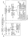
- Figure 1 is a block diagram of a point of care (POC) instrument and its operations.
- a sample of whole blood may be brought in at block 111.
- Some of the whole blood may be moved through a lysing well 112 to remove red cells so as to primarily get white blood cells at block 113.
- Some of the white blood cells may go to scattering based cytometry at block 114 and result in a count and five-part differentiation of the white blood cells at block 115.
- white blood cells may also go to block 116 for incubating with fluorescent tagged antibodies. This is for attaining information about an indication and/or amount of CD4, CDXX, malaria parasites, tuberculosis (TB), and so forth, at block 117.
- some of the whole blood may go to a scattering and cytometry block 118 to get RBC counts and hematocrit data.
- whole blood may to block 120 for lysing and absorption based information on the amount of hemoglobin in the blood.
- the items in the blocks of Figure 1 may be implemented on a microfluidic cartridge or card, which may be regarded as a hematology analyzer.
- One of the primary goals of the cartridge is to obtain complete blood count parameters which may include red blood cell count, white blood cell count, hemoglobin amount, hematocrit data, platelet count, and a five part differentiation of the white blood cells.
- Blocks 115, 119 and 121 may provide the complete blood count.
- Block 117 may provide analysis with fluorescence.
- the two major operations may be implemented on and achieved by a microfluidic cartridge, which may be as small as an ordinary credit card and disposable.
- lymphocytes may be tagged with a fluorescent or fluoro tag or marker.
- the cell may have an antigen and antibodies from a reservoir which may be provided on the cartridge, and an antibody may bind to a certain antigen.
- the subgroupings of the lymphocytes may have clinical significance. The subgroupings may result in groups of CD4, CD45, CDX, CDXX cells to allow doctors to note and/or deduce pathogens and the like, and to monitor HIV, AIDS, malaria, TB, and so on, of patients. Even monocytes may be labeled with fluorescent markers.
- the antibodies may be tagged to reduce a false alarm rate.
- Malaria may be one of the most common infectious diseases and an enormous public-health problem.
- the disease is regarded as being caused by protozoan parasites of the genus Plasmodium.
- the most serious forms of the disease may be caused by Plasmodium falciparum and Plasmodium vivax, but other related species (Plasmodium ovale and Plasmodium malariae) may also infect humans.
- This group of human-pathogenic Plasmodium species is often referred to as malaria parasites.
- Figure 2 is graph of a five-part differentiation of white cells based on data of small angle scattering versus large angle scattering plotted on the ordinate and abscissa axes, respectively, resulting in a plot of the five groups 131, 132, 133, 134 and 135 of white blood cells.
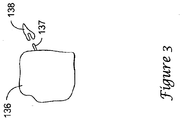
- Figure 3 shows a white blood cell 136, such as a lymphocyte, having an antigen 137 with an antibody 138 coming to it to match up like a key and lock. The respective cell may ultimately come from whole blood with an antigen on it.
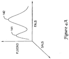
- Figure 4a is a three dimensional plot of lymphocytes with orthogonal measurements for the plotted data.
- the data are 3-D plotted with fluoro intensity (which indicates how many cells are labeled by the antibody) versus FALS on a plane parallel to the sheet with Figure 4a , with a third coordinate for SALS extending out from the sheet.
- Figure 4a shows a two peak (141 and 142) perspective.
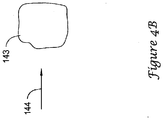
- Figure 4b shows an example cell 143 from a viewing direction looking towards the side of the graph of Figure 4a .
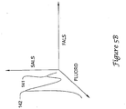
- the graph of Figure 5a is like that of Figure 4a except the first peak appears smaller in amplitude which may indicate a poor body response.
- Peak 141 of Figure 4a may indicate a good body response.
- a ratio of peak 141 to peak 142 may provide certain information of the health of the subject.
- Figure 5b shows the plot of SALS versus Fluoro revealing peaks 141 and 142.
- a red blood cell (RBC) count (cells/ ⁇ L), a platelet (PLT) count (cells/ ⁇ L), a mean cell volume (MCV), and a red cell distribution width (RDW) may be attained with an optical approach upon a blood sample.
- MCV is effectively a measurement of the average size of the RBCs.
- RDW is the variation of the size among the RBCs. A greater variation of the sizes of the RBCs, the greater is the RDW.
- An RBC count is an actual number of RBCs per unit volume of the blood under analysis.
- Hct is hematocrit which is RBC x MCV, and may amount to a measure of oxygen carrying capacity of the blood (i.e., total capacity of all of the cells in the unit volume under analysis). Hct may also be regarded as an amount of space that the RBCs take up in the blood, or the proportion of the whole blood that is composed of red blood cells.
- Hb is the amount of hemoglobin per unit volume of the sample under analysis.
- MCHC is the "mean cell hemoglobin concentration" which may be regarded as the concentration of hemoglobin per unit volume in each of the RBCs.
- MCHC Hb ⁇ Hct.
- a set of some measured parameters may include cell flow rate (FR), measurement time (T), dilution factor (DF), number of RBCs counted (N RBC ), number of platelets counted (N PLT ), the amount of hemoglobin (Hb), and the diameter (microns) of virtually each cell i (drbc i ).
- FR cell flow rate
- T measurement time
- DF dilution factor
- N RBC number of RBCs counted
- N PLT number of platelets counted
- Hb hemoglobin
- ⁇ drbc i > is the average of the measured cell diameters of the cells, denoted by the set ⁇ drbc i ⁇ .
- Module 121 may be used for determining an amount of hemoglobin (Hb) or hemoglobin concentration in the blood sample.
- the module may use hemoglobin absorption to determine the Hb.
- the amount of hemoglobin in the blood may be expressed in grams per liter.
- Figure 6a shows a graph of counting and classification of 5- and 6- ⁇ m beads, shown as groups 145 and 146, respectively.
- the plot is FALS versus SALS of the beads.
- the absolute count for each bead type appears to be within about five percent of the expected values.
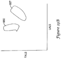
- Figure 6b shows results for a white blood cell plot from scattering data showing several groupings of the cells. The plot is FALS versus SALS of the cells according a point of care type of instrument.
- Three groups 147, 148 and 149 of white blood cells (lymphocytes, L, monocytes, M, and granulocytes, G, respectively) may be differentiated in the plot of Figure 6b .
- the total WBC count appeared within 6 percent of a similar measurement made on the same sample using a commercial hematology analyzer.
- Red VCSEL arrays may provide a solution to one of the most critical aspects in flow cytometry which may include the alignment of the focused laser spot with particle flow path.
- alignment in molded plastic parts such as disposable fluidic cartridges is challenging due to some imprecision associated with the use of such parts.
- Replacing a standard single laser with a linear array of lasers provides a way of determining a virtually exact path of a particular cell and allowing for self-alignment.
- the present POC cytometer may include microfluidic circuitry for whole-blood sample acquisition, reagent storage, continuous lysing of red blood cells, a three-dimensional hydrodynamic/geometric focusing of leukocytes into a blood-cell-sized core for flow cytometry, and sample and waste storage chambers. It may work directly from a single droplet (15 ⁇ L) of blood without any preparatory steps, minimize reagent use, and retain the sample, reagents, and waste on-card.
- Liquid flow in the micro-scale channels on the analysis cartridges may be laminar in nature, allowing miscible fluids (e.g., whole blood and water) to flow next to each other, mixing only through molecular and convective diffusion. This may enable exposure of biological particles (such as blood cells) for a controlled time duration, allowing selective lysing of red blood cells (RBC) via chemical and osmotic pressure so that the remaining white blood cells can be detected and characterized.
- RBC red blood cells
- This approach for the selective lysing of RBCs on a cartridge termed "lysing-on-the-fly" (LOF) may offer an advantage of all cells exposed to lysing agents for a same amount of time, unlike batch lysis performed in benchtop cytometers.
- Two-color light fluorescence capability on the light-scattering-based instrument may be used to perform a CD4/CD45 assay.
- the POC may also be an integrated scattering/fluorescence cytometer capable of a CD4, CD45, CD34, CDX, CDXX, and/or the like assay.
- the disposable card or cartridge may permit on-card staining of white blood cells with on-card mAbs and red cell lysing.
- the present POC hematology analyzer may be designed as a CLIA-waived instrument to perform the complete blood count (CBC) test.
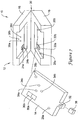
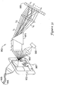
- FIG. 7 is a perspective view of an illustrative miniaturized portable cytometer. A version of this cytometer may be used conjunction with the present invention.
- the cytometer is generally shown at 10, and may include a housing 12 and a removable or replaceable cartridge 14.
- the illustrative housing 12 may include a base 16, a cover 18, and a hinge 20 that attaches the base 16 to the cover 18,
- the base 16 may include light sources 22a and 22b, associated optics and the necessary electronics for operation of the cytometer.
- the cover 12 may include a manual pressurizing element, pressure-chambers with control microvalves, and light detectors 24a and 24b with associated optics.
- the removable cartridge 14 may receive a sample fluid via a sample collector port 32.
- a cap 38 may be used to protect the sample collector port 32 when the removable cartridge 14 is not in use.
- the removable cartridge 14 may perform blood dilution, red cell lysing, and hydrodynamic focusing for core formation.
- the removable cartridge 14 may be constructed with fluidic circuits, some of which may be fabricated using a laminated structure with etched channels.
- the removable structure or cartridge 14 may be inserted into the housing when the cover 18 is in the open position.
- the removable cartridge 14 may include holes 26a and 26b for receiving registration pins 28a and 28b in the base 16, which help provide alignment and coupling between the different parts of the instrument.
- the removable cartridge 14 also may include transparent flow stream windows 30a and 30b, which are in alignment with the arrays of the light sources 22a and 22b, and light detectors 24a and 24b.
- the cover 18 may provide controlled pressures to pressure receiving ports 34a, 34b, and 34c in the removable cartridge 14 via pressure providing ports 36a, 36b and 36c, respectively.
- the cover 18 may be lifted and a new cartridge 14 placed and registered onto the base 16.
- a blood sample may be introduced into the sample collector 32.
- the cover 18 may be closed and the system manually pressurized. Pressurization may other than manual.
- the instrument may perform a white blood cell cytometry measurement and other measurements.
- the removable cartridge 14 may provide blood dilution, red cell lysing, and hydrodynamic focusing for core formation.
- the light sources 22a and 22b, light detectors 24a and 24b and associated control and processing electronics may perform differentiation and counting of white blood cells based on light scattering fluorescent signals. Rather than using a hinged construction for the housing 12, it is contemplated that a sliding cartridge slot or any other suitable construction may be used.
- Figure 8 is a schematic view of the illustrative cytometer of Figure 7 .
- the base 16 may include light sources 22a and 22b, associated optics and the necessary control and processing electronics 40 for operation of the cytometer.
- the base 16 may also include a battery 42 for powering the cytometer.
- the cover 18 is shown having a manual pressurizing element 44, pressure-chambers 46a, 46b and 46c with control microvalves, and light detectors 24a and 24b with associated optics.
- the removable cartridge 14 may receive a sample fluid via the sample collector port 32. When pressurized by the cover 18, the removable cartridge 14 may perform blood dilution, red cell lysing, and hydrodynamic focusing for core formation in the present device. Once formed, the core may be provided down a flow stream path 50, which passes the flow stream windows 30a and 30b of Figure 7 .
- the light sources 22a and 22b, and associated optics in the base may provide light through and to the core stream via the flow stream windows 30a and 30b.
- the light detectors 24a and 24b, and associated optics may receive scattered and non-scattered light from the core, also via the flow stream windows 30a and 30b, respectively.
- the controller or processor 40 may receive output signals from the detectors 24a and 24b, and differentiate, identify and count selected white blood cells that are present in the core stream.
- the removable cartridge 14 may include a fluid control block 48 for helping control the velocity of each of the fluids.
- the fluid control block 48 may include flow sensors for sensing the velocity of the various fluids and report the velocities to the controller or processor 40.
- the controller or processor 40 may then adjust the microvalves associated with pressure-chambers 46a, 46b and 46c to achieve the desired pressures and thus desired fluid velocities for proper operation of the cytometer.
- the removable cartridge 14 may have a waste reservoir 52 downstream of the flow stream windows 30a and 30b.
- the waste reservoir 52 may receive and store the fluid of the flow stream in the removable cartridge 14.
- the removable cartridge may be removed and disposed of in a container compatible with biological waste.
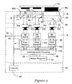
- Figure 9 is a more detailed schematic diagram showing the cytometer of Figure 8 with the cover 18 not yet depressed.
- Figure 10 is a more detailed schematic diagram showing the cytometer of Figure 8 with the cover depressed.
- the cover 18 is shown having a manual pressurizing element 44, pressure-chambers 46a, 46b and 46c, and control microvalves generally shown at 60.
- the light sources and detectors are not shown in these Figures.
- pressure chamber 46a may provide pressure to a blood sample reservoir 62.
- Pressure chamber 46b may provide pressure to a lyse reservoir 64, and pressure chamber 46c may provide pressure to a sheath reservoir 66.
- the size and shape of each pressure chamber 46a, 46b and 46c may be tailored to provide the desired pressure characteristics to the corresponding fluid.
- Pressure chamber 46a may include a first pressure chamber 70 and a second pressure chamber 72.
- a first valve 74 may be provided between the first pressure chamber 70 and the second pressure chamber 72 for controllably releasing the pressure in the first pressure chamber 70 to a second pressure chamber 72.
- a second valve 76 in fluid communication with the second pressure chamber 72, may controllably vent the pressure in the second pressure chamber 72.
- Each valve may be an array of electrostatically actuated microvalves that are individually addressable and controllable.
- Pressure chambers 46b and 46c may include similar valves to control the pressures applied to the lyse reservoir 64 and sheath reservoir 66, respectively.
- each valve may be an array of electrostatically actuated microvalves that are pulse modulated with a controllable duty cycle to achieve a controlled "effective" flow or leak rate.
- the removable cartridge 14 may have pressure receiving ports 34a, 34b, and 34c for receiving the controlled pressures from the cover 18.
- the controlled pressures may be provided to the blood reservoir 62, lyse reservoir 64 and sheath reservoir 66, as shown.
- the lyse reservoir 64 and sheath reservoir 66 may be filled before the removable cartridge 14 is shipped for use, while the blood reservoir 62 is filled from sample collector port 32.
- a blood sample may be provided to the sample collector port 32, and through capillary action, the blood sample may be sucked into the blood reservoir 62. Once the blood sample is in the blood reservoir 62, the cover 18 may be closed and the system may be pressurized.
- a flow sensor may be provided in-line with each fluid prior to hydrodynamic focusing.
- Each flow sensor 80, 100 and 102 may measure the velocity of the corresponding fluid.
- the flow sensors may be thermal anemometer type flow sensors, or microbridge type flow sensors.
- An output signal from each flow sensor 80, 100 and 102 may be provided to controller or processor 40.
- the controller or processor 40 may open the first valve 74 when the velocity of the blood sample drops below a first predetermined value and open the second valve 76 when the velocity of the blood sample increases above a second predetermined value.
- Valves 84, 86, 94 and 96 may operate in a similar manner to control the velocities of the lyse and sheath fluids.
- the manual pressurizing element 44 may be depressed.
- the pressure element may be substituted with a non-manual mechanism.
- the manual pressurizing element 44 may include three plungers, with each plunger received within a corresponding one of the first pressure chambers.
- the plungers may create a relatively high non-precision pressure in the first pressure chambers.
- Lower, controlled pressures may be built in the secondary chambers by opening the first valves 74, 84 and 94, which produce a controllable leak into the secondary chambers. If too much pressure builds up in the secondary pressure chambers, the corresponding vent valves 76, 86 and 96 may be opened to relieve the pressure.
- the normally open first valves 74, 84 and 94 may be closed while the vent valves 76, 86 and 96 are open.
- the vent valves 76, 86 and 96 may be closed, and the first valves 74, 84 and 94 may be opened to build a lower pressure P' in the secondary pressure chambers.
- the controlled pressure in the secondary pressure chambers may provide the necessary pressures to the fluidic circuit of the removable cartridge 14 to produce fluid flow for the blood, lyse and sheath.
- the velocity of the fluid flow may then be measured by the downstream flow sensors 80, 100 and 102.
- Each flow sensor may provide an output signal that is used by the controller or processor 40 to control the operation of the corresponding first valve and vent valve to provide a desired and constant flow rate for each fluid.
- Downstream valves generally shown at 110 may also be provided. Controller or processor 40 may close downstream valves 110 until the system is pressurized. This may help prevent the blood, lyse and sheath from flowing into the fluid circuit before the circuit is pressurized. In another illustrative example of the invention, downstream valves 110 may be opened by mechanical action when the cover is closed.
- FIG 11 is a schematic diagram showing the formation of a flow stream and core by the hydrodynamic focusing block 88 of Figure 9 .
- the hydrodynamic focusing block 88 may receive blood, lyse and sheath at controlled velocities from the fluid driver.
- the blood may be mixed with the lyse, causing the red blood cells to be removed.
- the lysing solution may have a pH lower than that of the red blood cells. This may often be referred to as red cell lysing or lyse-on-the-fly.
- the remaining white blood cells may be provided down a central lumen 150, which may be surrounded by sheath fluid to produce a flow stream 50.
- the flow stream 50 may include a core stream 160 surrounded by the sheath fluid 152.
- the dimensions of the channel may be reduced as shown so that the white blood cells 154 and 156 are in single file.
- the velocity of the sheath fluid may be about 9 times that of the core stream 160. However, the velocity of the sheath fluid and core stream 160 may remain sufficiently low to maintain laminar flow in the flow channel.
- Light emitters 22a and 22b, and associated optics may be provided adjacent one side of the flow stream 50.
- Light detectors 24a and 24b, and associated optics may be provided on another side of the flow stream 50 for receiving the light from the light emitters 22a and light from fluorescing particles via the flow stream 50.
- the output signals from the light detectors 24a and 24b may be provided to controller or processor 40, wherein they are analyzed to identify and/or count selected white blood cells in the core stream 160.
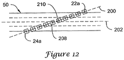
- Figure 12 is a schematic diagram showing an array 22a of light sources and an array 24b of light detectors for analysis of the core stream 160 via scattering of Figure 11 .
- the light sources are shown as "+" signs and the detectors are shown at boxes.
- the array of light sources may be provided adjacent one side of the flow stream 50, and the array of light detectors be provided adjacent the opposite side of the flow stream. Each of the light detectors may be aligned with a corresponding one of the light sources.
- the array of light sources and the array of light detectors are shown arranged along a light source axis 200 that is slightly rotated relative to the axis 202 of the flow stream 50.
- the array 22a of light sources may be an array of lasers such as vertical cavity surface emitting lasers (VCSELs) fabricated on a common substrate. Because of their vertical emission, VCSELs may be suited for packaging in compact instruments such as a miniaturized portable cytometer. Such cytometer may be wearable on a person's body.
- the VCSELs may be "red" VCSELs that operate at wavelengths that are less than the conventional 850 nm, or specifically in the 670 nm to 780 nm range. Red VCSELs may have a wavelength, power and polarization characteristic that is suited for scatter measurements.
- Some cytometer bench models may use a single 9 mW edge-emitting laser with a wavelength of 650 nm.
- the beam may be focused to a 10x100 micron elongated shape to cover the uncertainty in particle position due to misalignment and width of the core stream.
- the output power of the red VCSELs operating at 670 nm may typically be around 1 mW for a 10x10 micron emitter and 100-micron spacing.
- the total intensity of the light from a linear array of ten red VCSELs may be essentially the same as that of some prior art bench models.
- a linear array of lasers may be used to determining the lateral alignment of the path of the particles in the core steam.
- One source of uncertainty in the alignment of the particle stream may be the width of the core flow, which can lead to statistical fluctuations in the particle path position. These fluctuations may be determined from analysis of the detector data and can be used by the controller or processor 40 to adjust the valves of the fluid driver in order to change the relative pressures that are applied to the sample fluid and the supporting fluids to change the alignment of the selected particles in the flow stream.
- the cells may pass through several focused spots produced by the linear array of VCSELs.
- the cells may produce a drop in signal in the corresponding in-line reference detectors.
- the relative strengths of the signals may be used by the controller or processor 40 to determine the center of the particle path and a measure of the particle width.
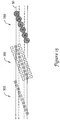
- the lasers 22a may be focused to a series of Gaussian spots 214 (intensity on the order of 1000W/cm 2 ) in the plane of the core flow.
- the spots 214 may be about the same size as a white blood cell (10-12 um).
- Illustrative Gaussian spots 214 are shown in Figure 13 .
- Arrays 24a of detectors and their focusing optics may be provided on the opposite side of the fluid stream 50. Lenses with fairly large F-numbers may be used to provide a working space of several hundred microns for the cytometer section of the removable cartridge.
- Particle velocity can be an important parameter in estimating the particle size from light scatter signals. In some cytometry, the particle velocity may be extrapolated from the pump flow rates.
- a limitation of this approach is that the pumps should be very precise, the tolerance of the cytometer flow chambers should be tightly controlled, no fluid failures such as leaks should occur, and no obstructions such as microbubbles should be introduced to disturb the flow or core formation.
- the system may measure the time required for each cell to pass between two adjacent or successive spots. For example, and with reference to Figure 12 , a cell may pass detector 208 and then detector 210. By measuring the time required for the cell to travel from detector 208 to detector 210, and by knowing the distance from detector 208 to detector 210, the controller or processor 40 may calculate the velocity of the cell. This would be an approximate velocity measurement. This is often referred to as a time-of-flight measurement. Once the velocity is known, the time of travel through the spot on which the particle is centered (a few microseconds) may provide a measure of particle length and size.
- the particle velocity can also be used to help control the fluid driver.
- the replaceable cartridge of Figure 7 may be manufactured from a plastic laminate or molded parts. While such manufacturing techniques may provide inexpensive parts, they are typically less dimensionally precise and repeatable, with asymmetrical dimensions and wider tolerance cross-sections. These wider tolerances may produce variations in particle velocity, particularly from cartridge to cartridge.
- the time-of-flight measurement discussed herein may be used by the controller or processor 40 to adjust the controlled pressures applied to the blood, lyse and sheath fluid streams such that the particles in the core stream have a relatively constant velocity.
- laser beams may be focused both along the cell path and across the cell path. Additionally, multiple samples across the cell may be analyzed for texture features, to correlate morphological features to other cell types. This may provide multiple parameters about cell size that may help separate cell types from one another.
- Another advantage of using a linear array 22a of lasers rather than a single layer configuration is that a relatively constant light illumination may be provided across the flow channel. This may be accomplished by overlapping the Gaussian beams 214 from adjacent VCSELs 22a, as shown in Figure 13 . In single laser systems, the light illumination across the flow channel may vary across the channel. Thus, if a particle is not in the center of the flow channel, the accuracy of subsequent measurements may be diminished.
- each detector 24a in Figure 12 may be a single in-line detector. To measure FALS and SALS scatter, however, each detector 24a may further include two annular detectors disposed around the in-line detector, as shown in Figure 14 .
- a VCSEL 218 is shown providing light in an upward direction. The light may be provided through a lens 220, which can focus the light to a Gaussian spot in the plane of the core flow. Lens 220 may be a microlens or the like, which is either separate from or integrated with the VCSEL 218. The light may pass through the core flow, and be received by another lens 222, such as a diffractive optical element.
- Lens 222 may provide the light to in-line detector 226 and annular detectors 228 and 230.
- the in-line detector 226 may detect the light that is not significantly scattered by the particles in the core stream.
- Annular detector 228 may detect the forward scatter (FALS) light, and annular detector 230 may detect the small angle scatter (SALS) light.
- FALS forward scatter
- SALS small angle scatter
- Figure 15 shows another illustrative example that may include three separate arrays of light sources and light detectors.
- Each array of light sources and light detectors may be positioned along a different light source axis that is slightly rotated relative to the central flow axis of the flow stream.
- the optics associated with each array may be optimized for a particular application or function. For detecting small angle scattering (SALS), laser light that is well-focused on the plane of the core flow is desirable. For detecting forward scattering (FALS), collimated light is desirable.
- SALS small angle scattering
- FALS forward scattering
- a first array of light sources and light detectors is shown at 300.
- the light sources and light detectors may be arranged in a linear array along a first light source axis.
- the first light source axis may be rotated relative to the flow axis of the flow stream.
- the light sources and light detectors may be similar to that described above with respect to Figure 12 , and may be used to measure, for example, the lateral alignment of the cells in the flow stream, the particle size, and the velocity of the particles.
- the user may obtain a removable cartridge and provide a blood sample to the sample collector port 32 (see Figure 7 ) of the removable cartridge.
- the blood sample may be collected by, for example, a finger prick.
- the user may then insert the removable cartridge into the housing, and manually pressurize the system.
- the miniaturized portable cytometer may then provide a reading that indicates if the user should seek medical treatment.
- the reading may be a visual reading, an audible sound or any other suitable indicator.
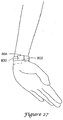
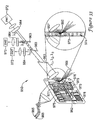
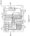
- a catheter 804 ( Figure 27 ) or the like may be inserted into a vein of the user and attached to the sample collector port 32. This may allow the system to automatically collect a blood sample from the user whenever a reading is desired.
- the miniaturized portable cytometer may be implanted in the user, with the sample collector port 32 connected to a suitable blood supply.
- Figure 16 is a schematic view of certain features of an illustrative removable cartridge.
- the illustrative removable cartridge is generally shown at 400, and may be similar to removable cartridge 14 described herein. It should be understood that the removable cartridge 400 is only illustrative, and that the present example can be applied to many microfluidic cartridges, regardless of form, function or configuration. For example, the present example may be applied to removable cartridges adapted for flow cytometry, hematology, immunoassays, clinical chemistry, blood chemistry analysis, urinalysis, blood gas analysis, virus analysis, bacteria analysis, electrolyte measurements, and so on.
- removable cartridges of the present system may be made from any suitable material or material system including, for example, glass, silicon, one or more polymers, or any other suitable material or material system, or combination of materials or material systems.
- the illustrative removable cartridge 400 includes a first measurement channel 402 and a second measurement channel 404, although more or less measurement channels may be used, as desired.
- the first measurement channel 402 in the illustrative example, is a red blood cell measurement channel
- the second measurement channel 404 is a white blood cell measurement channel.
- a whole blood sample is received by the removable cartridge 400 via blood receiving port 406, which through capillary action, draws in a known amount of blood into an anti-coagulant coated blood sample storage capillary 408.
- a sample push (P) pressure is provided to a sample push fluid reservoir. When pressure is applied, the sample push fluid is forced from the sample push fluid reservoir into a blood sample push channel 410.
- a valve 412 and a flow sensor 414 may be provided in line with the blood sample push channel 410.
- the valve 412 may be controlled to open when it is desirable to push the blood sample through the fluidic circuit.
- the flow sensor 414 may measure the flow rate of the blood sample push fluid, and thus the blood sample flow rate through the anti-coagulant coated capillary 408. The flow rate provided by the flow sensor 414 may be used to help control the sample push (P) pressure that is provided to the removable cartridge 400.
- the whole blood sample is partitioned and provided to the red blood cell measurement channel 402 and the white blood cell measurement channel 404 via branch 416.
- a valve 418 is provided in line with the branch to control the blood sample flow into the red blood cell measurement channel 402
- a valve 420 is provided to control the blood sample flow into the white blood cell measurement channel 404.
- a red blood cell sphering reagent pressure SP is provided to a sphering reagent reservoir.
- SP red blood cell sphering reagent pressure
- a valve 426 and a flow sensor 428 may also be provided in line with the sphering reagent channel 424.
- the valve 426 may be controlled to open when it is desirable to push the sphering reagent into the fluidic circuit.
- the flow sensor 428 may measure the flow rate of the sphering reagent, and provide a measure of the sphering reagent flow rate through the sphering reagent channel 424.
- the flow rate provided by the flow sensor 428 may be used to help control the sphering pressure (SP) that is provided to the removable cartridge 400 by the pressure source/controller.
- SP sphering pressure
- the sphering reagent is pushed into an intersecting region 430 at a sphering reagent flow rate, and the blood sample is pushed into the intersecting region 430 at a blood sample flow rate.
- the blood sample flow rate and the sphering reagent flow rate may be controlled by a pressure source/controller.
- the intersection region 430 may be configured so that the sphering reagent flows circumferentially around the blood sample when both fluids are flowing through the intersection region 430.
- the sphering reagent flow rate may be higher than the blood sample flow rate, which may help improve the flow characteristics in a downstream sphering-on-the-fly channel 432, and in some cases, to help form a thin ribbon of blood that is completely and uniformly surrounded by the sphering reagent.
- Such a ribbon flow may help the sphering reagent uniformly sphere the red blood cells as they travel through the sphering-on-the-fly channel 432.
- the length of the sphering-on-the-fly channel 432, in conjunction with the flow rate of the sphering reagent and blood sample, may be set such that the blood sample is exposed to the sphering reagent for an appropriate amount of time.
- a sheath fluid (SH) pressure may be provided to a sheath fluid reservoir. When pressure is applied, the sheath fluid is forced from the sheath fluid reservoir into a sheath channel 434.
- a valve 436 and a flow sensor 438 may be provided in line with a sheath channel 434.
- the valve 436 may be controlled to open when it is desirable to push the sheath fluid into the fluidic circuit.
- the flow sensor 438 may measure the flow rate of the sheath fluid, and may provide a measure of the sheath flow rate through the sheath channel 434.
- the flow rate provided by the flow sensor 438 may be used to help control the sheath pressure (SH) that is provided to the removable cartridge 400.
- the sheath fluid is provided to an intersecting region 440 at a sheath fluid flow rate
- the sphered blood sample is provided to the intersecting region 440 at a sphered blood sample flow rate.
- the sphered blood sample flow rate and the sheath flow rate may be controlled by a pressure source/controller.
- the intersection region 440 may be configured so that the sheath fluid flows circumferentially around the sphered blood sample when both fluids are flowing through the intersection region 440.
- the sheath flow rate is significantly higher than the sphered blood sample flow rate, which may help improve core formation in a downstream flow cytometry channel 442.
- the intersecting region 440 may be configured to hydrodynamically focus and arrange the sphered blood cells in a single file core so that each red blood cell can be individually optically interrogated by an analyzer as they pass through an optical window region 444 in the removable cartridge 400.
- the fluid that passes through the cytometry channel 442 is directed to an on-board waste reservoir,
- a white blood cell lysing reagent pressure (L) may be provided to a lysing reagent reservoir.
- L white blood cell lysing reagent pressure
- a valve 456 and a flow sensor 458 may be provided in line with the lysing reagent channel 454.
- the valve 456 may be controlled to open when it is desirable to push the lysing reagent into the fluidic circuit.
- the flow sensor 458 may measure the flow rate of the lysing reagent, and provide a measure of the lysing reagent flow rate through the lysing reagent channel 454.
- the flow rate provided by the flow sensor 458 may be used to help control the lysing pressure (L) that is provided to the removable cartridge 400 by the pressure source/controller.
- the lysing reagent is provided to an intersecting region 460 at a lysing reagent flow rate, and the blood sample is provided to the intersecting region 460 at a blood sample flow rate.
- the blood sample flow rate and the lysing reagent flow rate may be controlled by a pressure source/controller.
- the intersection region 460 may be configured so that the lysing reagent flows circumferentially around the blood sample when both fluids are flowing through the intersection region 460.
- the lysing reagent flow rate may be higher than the blood sample flow rate, which may help improve the flow characteristics in a lysing-on-the-fly channel 462, and in some cases, to help form a thin ribbon of blood that is completely and uniformly surrounded by the lysing reagent.
- Such a ribbon flow may help the lysing reagent uniformly lyse the red blood cells as they travel through the lysing-on-the-fly channel 462.
- the length of the lysing-on-the-fly channel 462, in conjunction with the flow rate of the lysing reagent and blood sample, may be set such that the blood sample is exposed to the lysing reagent for an appropriate amount of time.
- a sheath fluid (SH) pressure may be provided to a sheath fluid reservoir. When pressure is applied, the sheath fluid is forced from the sheath fluid reservoir into a sheath channel 464.
- a valve 466 and a flow sensor 468 may be provided in line with a sheath channel 464. The valve 466 may be controlled to open when it is desirable to push the sheath fluid into the fluidic circuit.
- the flow sensor 468 may measure the flow rate of the sheath fluid, and may provide a measure of the sheath flow rate through the sheath channel 464. The flow rate provided by the flow sensor 468 may be used to help control the sheath pressure (SH) that is provided to the removable cartridge 400.
- the sheath flow rate through sheath channel 464 is the same as the sheath flow rate through sheath channel 434. However, in other cases, the sheath flow rate through sheath channel 464 may be different from the sheath flow rate through sheath channel 434.
- the sheath fluid is provided to an intersecting region 470 at a sheath fluid flow rate
- the lysed blood sample is provided to the intersecting region 470 at a lysed blood sample flow rate.
- the lysed blood sample flow rate and the sheath flow rate may be controlled by a pressure source/controller.
- the intersection region 470 may be configured so that the sheath fluid flows circumferentially around the lysed blood sample when both fluids are flowing through the intersection region 470.
- the sheath flow rate is significantly higher than the lysed blood sample flow rate, which may help improve core formation in a downstream flow cytometry channel 472.
- the intersecting region 470 may be configured to hydrodynamically focus and arrange the white blood cells in the lysed blood sample in a single file core so that each white blood cell can be individually optically interrogated by an analyzer as they pass through an optical window region 474 in the removable cartridge 400.
- the fluid that passes through the cytometry channel 472 is provided to an on-board waste reservoir.
- an absorption measurement channel may also be provided.
- a portion of the lysed blood sample is provided to absorption channel 480.
- a valve 482 may be provided to selectively allow a portion of the lysed blood sample to pass to the absorption channel or region 484.
- the analyzer may include a light source to illuminate the absorption channel or region 484, as well as a detector to detect the light that is not absorbed by the lysed blood sample in the absorption channel or region 484. The analyzer may then determine an absorption level, from which a bulk absorption based hemoglobin measurement can be made.
- the absorption channel 484 may be situated downstream of the cytometry channel 472, if desired.
- a whole blood sample is provided directly, such as from branch 416, to an absorption channel.
- the absorption channel includes a mechanism to lyse the red blood cells prior to taking the absorption measurement.
- the illustrative removable cartridge 400 is adapted to perform a complete blood count (CBC) analysis on a whole blood sample, it is contemplated that other removable cartridge configurations and analysis types may be used, as desired.
- CBC complete blood count
- FIG 17 is a schematic flow diagram showing an illustrative approach for analyzing a blood sample using a removable cartridge.
- a blood sample is first acquired at step 600.
- the blood sample is provided to an anti-coagulant coated capillary in a removable cartridge.
- the blood sample is then partitioned and provided to a red blood cell and platelet (RBC/P) measurement channel 604 and a white blood cell (WBC) measurement channel 606.
- RBC/P red blood cell and platelet
- WBC white blood cell
- the red blood cells are first sphered as shown at 612, and then hydrodynamically focused and provided single file down a RBC/P cytometry channel 614 in the removable cartridge.
- a light source 616 such as a vertical cavity surface emitting laser (VCSEL) shines light on the individual cells as they pass by an analysis region of the RBC/P cytometry channel 614.
- VCSEL vertical cavity surface emitting laser
- an array of VCSEL devices is provided, and only the VCSEL(s) that is/are aligned with the individual cells as they pass by the analysis region of the RBC/P cytometry channel 614 is activated.
- Some of the incident light provided by the VCSEL is scattered, and a detector 618 detects the scattered light. In some cases, the detector 618 may detect forward angle scatter light (FALS), small angle scatter Light (SALS) and large angle scatter light (LALS).
- FALS forward angle scatter light
- SALS small angle scatter Light
- LALS large angle scatter light
- a laser (or other) source is focused into the RBC/P cytometer channel 614, either as an elongated line source or as two separate spot sources.
- High quality collection optics may be used to form a sharp image of the cells and focused illumination onto an opaque screen containing one, two or more parallel slits whose longitudinal axes are arranged orthogonal to the flow direction in the RBC/P cytometer channel 614.
- the distance between the slits may be, for example, on the order of the mean cell separation expected in the RBC/P cytometer channel 614.
- the opaque screen containing the slits may be placed in front of one or more detectors 618.
- the image of a cell passes over a slit, it obscures the light incident on the slit and causes a reduction in the signal on the detector 618, producing a pulse waveform whose width is proportional to the cell diameter.
- the two waveforms may permit the calculation of the cell flow velocity, and hence the cell size. High signal-to-noise may be obtained using this technique, which permits easy counting of events and identification of multiple cell events. Pulse width and amplitude may further enable the discrimination of some cell types.
- an image of both the cell and the light source is imaged on a double slit aperture placed in front of the detector 618.
- the double slit aperture provides a well defined geometrical aperture and high signal-to-noise ratio to count cells.
- signals from the slits may permit the accurate measurement of cell flow velocity, which in turn may permit the calculation of cell diameter.
- a number of parameters may be measured during this analysis, including for example, sample flow rate (FR), measurement time (T) duration, and sample dilution factor (DF).
- FR sample flow rate
- T measurement time
- DF sample dilution factor
- the red blood cells are first lysed as shown at 632, and then hydrodynamically focused and provided single file down a WBC cytometry channel 634 in the removable cartridge.
- a light source 636 such as a vertical cavity surface emitting laser (VCSEL) shines light on the individual cells as they pass by an analysis region of the WBC cytometry channel 634.
- VCSEL vertical cavity surface emitting laser
- an array of VCSEL devices is provided, and only the VCSEL(s) that is/are aligned with the individual cells as they pass by the analysis region of the WBC cytometry channel 634 is activated.
- Some of the incident light provided by the VCSEL is scattered, and a detector 638 detects the scattered light.
- the detector 638 detects forward angle scatter light (FALS), small angle scatter light (SALS), and large angle scatter light (LALS).
- FALS forward angle scatter light
- SALS small angle scatter light
- LALS large angle scatter light
- a number of parameters may be measured during the analysis including, for example, on-axis cell volume, total WBC count, and WBC five (5) part differentiation.
- FIG 18 is a flow diagram showing an illustrative approach for obtaining a number of red blood cell parameters.
- a blood sample is acquired at step 660.
- the blood sample is diluted to a desired Dilution Factor (DF), and sphered as shown at 664.
- DF Dilution Factor
- the diluted and sphered blood cells are then hydrodynamically focused and provided single file down a RBC/P cytometry channel in the removable cartridge.
- a light source 616 such as a vertical cavity surface emitting laser (VCSEL), shines light on the individual cells as they pass by an analysis region of the RBC/P cytometry channel. Some of the incident light provided by the VCSEL(s) is scattered, and a detector may be used to detect the scattered light.
- VCSEL vertical cavity surface emitting laser
- the detector detects both forward angle scattered light (FALS) and small angle scattered light (SALS) for each cell.
- a processor or the like may then map the two independent scatter parameters, namely SALS and FALS, for each cell to a cell diameter parameter and a cell hemoglobin concentration parameter as follows: S SALSi , S FALSi ⁇ > drbc i , CHC i
- step 670 determines if the intensity of the scatter S SALSi plus S FALSi is not greater than a predetermined detection threshold.
- control is passed back to step 668.
- step 672 determines if the sum of S SALSi and S FALSi is greater than a predetermined platelet threshold. If the sum of S SALSi and S FALSi is not greater than the predetermined platelet threshold, it is determined that the particle "i" is a platelet, and control is passed to step 674.
- Step 674 increments the number of counted platelets (N Plt ) by one, and passes control back to step 668.
- Step 676 increments the number of counted red blood cells (N RBC ) by one, and passes control to step 678.
- Step 678 determines if a predetermined measurement time has been reached. If not, control is passed back to step 668.
- Step 680 shows a number of measured parameters including, for example, sample flow rate (FR), measurement time (T) duration, sample dilution factor (DF), number of red blood cells counted (N RBC ), number of platelets counted (N Plt ), the diameter of each cell (drbc i ) and hemoglobin concentration of each cell (CHC i ).
- FR sample flow rate
- T measurement time
- DF sample dilution factor
- N RBC number of red blood cells counted
- N Plt number of platelets counted
- CHC i hemoglobin concentration of each cell
- FIG 19 is a schematic flow diagram showing another illustrative approach for analyzing a blood sample.
- a blood sample is acquired, and provided to a blood sample reservoir, as shown at step 700.
- the blood sample is provided to an anti-coagulant coated capillary in a removable cartridge, and diluted.
- the blood sample is then partitioned and provided to a red blood cell and platelet (RBC/P) measurement channel 704 and a white blood cell (WBC) measurement channel 740.
- RBC/P red blood cell and platelet
- WBC white blood cell
- the red blood cells are first sphered as shown at 706, and then hydrodynamically focused and provided single file down a RBC/P cytometry channel 708 in the removable cartridge.
- a first light source 710 such as a vertical cavity surface emitting laser (VCSEL) and associated optics, provides a focused light beam on the individual cells as they pass by an analysis region of the RBC/P cytometry channel 708.
- VCSEL vertical cavity surface emitting laser
- an array of VCSEL devices is provided, and only the VCSEL(s) that is/are aligned with the individual cells as they pass by an analysis region of the RBC/P cytometry channel 708 is/are activated.
- the individual cells/particles pass through the focused incident light beam, some of the light is blocked, scattered or otherwise obstructed, which can be detected by a detector (not shown).
- a detector not shown.
- the leading and/or trailing edge of each cell can be detected.
- the flow rate and thus the cell velocity can be determined. With the cell velocity determined, the length of time that a cell blocks, scatters or otherwise obstructs the light beam can be correlated to cell size and/or cell volume.
- another light source 714 and associated optics may be provided by an analyzer.
- the associated optics of light source 714 may collimate the light, and measure off-axis scatter, such as SALS and FALS scatter.
- SALS and FALS scatter can be used to measure, for example, a number of red blood cells counted (N RBC ) 716, number of platelets counted (N Plt ) 722, the diameter of each cell (drbc i ), the cell volume 718, and hemoglobin concentration 720 of each cell (CHC i ).
- the red blood cells are lysed, and dye is injected as appropriate, as shown at 742.
- the cells are then hydrodynamically focused and provided single file down a WBC cytometry channel 744 in the removable cartridge.
- a light source 746 such as a vertical cavity surface emitting laser (VCSEL), shines light on the individual cells as they pass by an analysis region of the WBC cytometry channel 744.
- VCSEL vertical cavity surface emitting laser
- an array of VCSEL devices is provided, and only the VCSEL(s) that is/are aligned with the individual cells as they pass by the analysis region of the WBC cytometry channel 744 is activated.
- the individual cells/particles pass through the focused incident light beam, some of the light is blocked, scattered or otherwise obstructed which may be spotted by a detector (not shown).
- a detector not shown.
- the leading and/or trailing edge of each cell can be detected.
- the flow rate and thus the cell velocity can be determined.
- the length of time that a cell blocks, scatters or otherwise obstructs the light beam can be correlated to cell size and/or cell volume.
- a light source 750 and associated optics and/or polarizers may be provided.
- the associated optics of light source 750 may collimate the light, and measure off-axis scatter, such as SALS, FALS and LALS scatter, as shown at 754.
- SALS, FALS and LALS scatter can be used to measure, for example, the number of white blood cells counted (N WBC ) 752, as well as to help with white blood cell differentiation, as shown at 756.
- one or more polarizers is/are provided to polarize the light provided by the light source, and the level of polarization extinction/rotation detected at the detector may be used to help perform white blood cell differentiation, but this is not required in all examples.
- a separate module may be used for determining an amount of hemoglobin (Hb) or hemoglobin concentration in the blood sample.
- the module may use hemoglobin absorption to determine the Hb.
- the amount of hemoglobin in the blood may be expressed in grams per liter or other unit combinations.
- the cells that exit the WBC cytometry channel 744 may be provided to a bulk absorption channel 760.
- a light source 762 may shine light onto the cells present in the absorption channel 760, and a detector 764 may detect the light that is not absorbed by the resident cells.
- the absorption channel 760 may thus be used to measure the bulk absorption level of the resident cells.
- the absorption level may provide, for example, a measure of the bulk or mean cell hemoglobin concentration in the blood sample.
- the hemoglobin channel may have re-zeroing optics and auto focus and/or alignment.
- Light source 762 may be a LED having an output close to the center of the absorption peak, thus possibly making a filter unnecessary.
- There may be a curvette for receiving and holding a sample to be evaluated in terms of hemoglobin.
- Figure 20 shows an example of an HGB card 770 or module.
- a lysing reagent deposition region 771 showing where there is a deposition/printing of the dry lysing powder.
- a budged corner 772 at the very last turns in a region 773 showing a bubble trap arrangement to eliminate air bubbles generated during blood lysing by the dry lysing powder so as to improve the HGB measurement accuracy.
- Figure 21 shows a cytometer cartridge 500 showing a scattering optical subsystem 501 and fluorescent optical subsystem 502.
- Optical subsystem 501 may include windows or openings 30a on each side of flow channel 530 and optical subsystem 502 may include windows or openings 30b.
- there may be a window or opening on each side of flow channel 530.
- the openings may have optical inserts or lenses.
- This cytometer may be implemented for wearing, attachment on, or insertion in a person's body
- Figure 22 shows systems 503 and 504 which may incorporate optical subsystems 501 and 502, respectively.
- System 503 may also include VCSEL array 22a and detector array 24a for scattering measurements of particles, such as white blood cells, in core stream 160.
- This system is may be used for the counting and classification of lymphocytes and neutrophils.
- Self-alignment is may be enabled by a red VCSEL-array based optical subsystem. Illustrative examples of scattering system 503 are described herein.
- System 504 may be a fluorescent exciting and detection mechanism used for identifying and counting specific subclasses of white blood cells and blood-based proteins.
- the detection of subclasses of white blood cells may be enabled by the availability of suitable antibodies, many of which are commercially available in a fluorescently conjugated form.
- Figure 23 shows an outline sketch of blood composition and the cells that may be subject to counting and identification by fluorescent system 504.
- the red blood cells may be removed form the sample to be looked with the cytometer by lysing as noted herein.
- the platelets may be kept as the small size does not affect the results of the cytometer when checking the white blood cells.
- the CD4-positive T-cells 505, shown in the structure of Figure 23 have proportions and counts in blood that may be very important in following a clinical course of an HIV infection.
- An antibody with a marker added that associates with CD4 may be mixed in the sample of blood to get a resultant "Y"-looking structure of the antibody (AB) 506 and its marker (M) 507, attached to CD4 cell 505, as shown in Figure 24a .
- Light source 22b may emit light which may be absorbed by marker 507.
- marker 507 may fluoresce and emit light of a particular wavelength which may be detected to identify CD4 cell 505.
- Checking blood for anthrax may be another application of the present cytometer.
- Antibodies 508 for the anthrax-causing bacteria 509 may be mixed with the blood sample.
- the antibodies may associate with bacteria 509.
- the antibodies may have markers 510 that fluoresce upon impingement of light.
- the "Y" structure of antibody 508 is shown in Figure 24b .
- Markers 510 emit a light of a particular bandwidth which may be different from the bandwidth of marker 507 of antibody 506 for CD4 cell 505. So the anthrax problem may be identified separately from the HIV problem in the same blood sample test by the fluorescent emissions having different wavelengths, colors or signatures.
- the number of different problems being detected at the same time in the same blood sample may be many more than two.
- Neupogen R (a type of protein) may be regarded for providing neutrophil counts in cancer patients undergoing myelosuppressive chemotherapy. While doing this therapy, there may a need to accurately monitor the white blood cell counts (specifically neutrophils, monocytes and platelet counts during the Neupogen R therapy period).
- the present cytometer may be used by untrained personnel to monitor such parameters of chemotherapy patients in their homes.
- the miniaturized portable cytometer may also be used in biowarfare. It may be used for quantitative detection and identification of biowarfare agents. This detection and identification may be based antibody-antigen type immunoassay that may be implemented with fluorescent measurements. The environment, water and food may be monitored for any possible presence of biological agents. It may involve sample collection and preparation appropriated for the cytometer. Other applications of the cytometer may include high throughput analysis (using the fluorescent detection features) and sequencing of DNA and RNA, studying the response of cell to potential drugs, immunophenotyping of leukemia and lymphomas and monitoring residual disease in cancer patients, and cell sorting and cell isolation, including highspeed separation of rare event populations.
- Certain applications and uses may be accomplished with the single, portable, miniaturized, integrated scattering and multi-color fluorescent, low-power, low-cost cytometry instrument having a compact precision fluid driving system, not requiring operator intervention or adjustment during the analytical phase, not requiring trained personnel to operate the instrument, and using sanitary, disposable plastic- or other material-based microfluidic cartridges 14 having integrated optics and internal blood sample processing, among other features.
- System 504 of Figure 22 may have a laser light source 22b positioned to direct light 511 at particles 512 flowing single file through flow channel 530.
- particles 512 may include structures 513 and 514 of Figures 24a and 24b , respectively.
- Light 511 may be from a red or a blue laser source, such as a light emitting diode (LED), which may have a bandwidth of, for example, 650 to 700 nanometers or 380 to 420 nanometers, respectively.
- LED light emitting diode
- Other types of sources having appropriate wavelengths may be used for light 511.
- As light 511 impinges fluorescent markers 507 and 510, these markers may fluoresce and emit light 515 and 516, respectively.
- light 515 and light 516 may have different wavelengths. Thus, structures 513 and 514 not only may be identifiable by the wavelengths of their emitted light but can be differentiated form each other in the same sample, blood or otherwise.
- Light 515 and 516 may go to a dichroic beam splitter 517 which separates the two beams by directing each of them in different directions. Beam 516 may go to a fluorescence photo detector 518 for detection and conversion of light 516 into an electrical signal 520 to processor 40. Beam 515 may go to a fluorescence photo detector 521 for detection and conversion of light 515 into an electrical signal 522 to processor 40.
- Band pass filter 519 which is in the path of beam 516, may filter out light 511 from light source 22b that managed to be present in beam 516.
- Band pass filter 523 may serve the same purpose for beam 515 as filter 519 for beam 515.
- a mirror 524 may be used to redirect beam 515 for purposes of detector 521 location for the possibility of more compact packaging of detection system 504 or for other reasons.
- Mirror 524 may on the other hand be another dichroic beam splitter for splitting out light 525 of a wavelength different from that of beams 515 and 516. More splitters might be used in a cascade-like or other structure to split out light of still other frequencies.
- Also going to processor 40 is a signal from detector array 24a of scattering detection system 503. It may be noted that light sources 22a and 22b may be replaced with one light source.
- Splitter 517 may be replaced with other mechanisms for separating out the light of various wavelengths or selecting certain wavelengths. They may include notch and step function filters of various kinds, tunable diffraction gratings, thin film dielectric stacks, mirror beam splitters, photonic bandgap filters, photonic crystals, tunable band pass filters, etalon comb and other structures, wafers having light guides with structural or other filtering, silicon or glass wafers having a waveguide and perforations of a specific size and pitch for absorbing/filtering, and so on.
- notch and step function filters of various kinds, tunable diffraction gratings, thin film dielectric stacks, mirror beam splitters, photonic bandgap filters, photonic crystals, tunable band pass filters, etalon comb and other structures, wafers having light guides with structural or other filtering, silicon or glass wafers having a waveguide and perforations of a specific size and pitch for absorbing/filtering, and so on.
- Figure 25 shows an illustrative example of the fluorescence optical subsystem 502.
- a beam 511 may be emitted by light source 22b and focused onto a particle 512 by a microlens 526 through window 30b.
- Light beam 511 may or may not be collimated.
- Particle 512 may have a marker that fluoresces and emits a light beam 515, 516 through window 30b, a thin film coating filter 527 and a microlens 528, respectively.
- Filter 527 may filter out light 511 from light source 22b.
- Filter 527 may be a dielectric stack situated under lens 528 and be a notch or step function filter to block source 22b light 511.
- Lens 528 may focus fluorescent light emitted from the marker into a beam 515/516 which may go on to a beam splitter such as splitter 517. Beam 515/516 may or may not be collimated.
- An opaque or absorptive layer 529 may be formed around or before and after window 30b or lens 528 on a glass, quartz or plastic (laminated or not) substrate 531 of flow channel 530. Layer 529 may block any light 511 emanating from light source 22b from exiting out with fluorescent light 515/516.
- Layer or blocking filter 529 may be a thin film that is black or opaque to the wavebands desired to be blocked. Filter 529 could be a notch or step function filter.
- the other glass, quartz or plastic (laminated or not) substrate 532 may form flow channel 530 for the core flow of particles 512.
- the material of substrates 531 and 532, windows 30b and lens 526 and 528 should not contain ingredients that may fluoresce.
- the direction of light 511 from source 22b may be about 90 degrees relative to the direction of fluorescent light 515/516 emitted from particle 512. This angle between source light 511 and emitted fluorescent light 515/516 may effectively reduce or eliminate source light emanating out with fluorescent light 515/516.
- the angle of the direction of light 511 from source 22b in the example may be about 45 degrees relative to the direction of the longitudinal dimension flow channel 530 or the direction of the core flow of particles 512. However, in some applications, the angle between the directions of light 511 and light 515/516 may be between 0 and 120 degrees.
- Figure 26 shows a diagram of cytometer configuration of Figure 22 , but with the placement of lenses 541 and 542.
- windows and openings 30b may or may not have micro lenses in addition to lenses 541 and 542.
- a single light source version (in lieu of sources 22a and 22b) may also have a similar lens and/or micro lens optical arrangement.
- FIG 27 is a perspective view of an illustrative example of a miniaturized portable cytometer having both scattering and fluorescent detection and monitoring adapted to be worn around the wrist or palm.
- This cytometer 800 may be similar to that shown in Figures 7 , 21 , 30 , 31 , 33 and/or 37.
- a band 802 may secure the miniaturized portable cytometer 800 to the wrist of a user.
- the user may obtain a removable cartridge and provide a blood sample to the sample collector port 32 (see Figures 7 , 21 , 22 and 26 ) of the removable cartridge.
- the blood sample may be collected by, for example, a finger prick.
- the user may then insert the removable cartridge into the housing, and manually pressurize the system.
- the miniaturized and portable cytometer may then provide a reading that indicates if the user should seek medical treatment.
- the reading may be a visual reading, an audible sound or any other suitable indicator.
- a catheter 804 or the like may be inserted into a vein of the user and attached to sample collector port 32. This may allow the system to automatically collect a blood sample from the user whenever a reading is desired.
- the miniaturized portable cytometer may be implanted in the user, with sample collector port 32 connected to a suitable blood supply.
- a flow channel 865 may have a cross-section of about 100x200 microns.
- a core stream 867 of particles 868 maybe about 15-20 microns wide.
- the spot of light 866 may about 20x180 microns for a 670 nm red light.
- the core may move side-to-side as shown by particle positions 871 and 872.
- Scattered light 869 from the light 866 impinging the core stream 867 of single-file white blood cells 868 may be plotted with a photo detector 873 that measures a 1 to 3 degree band (FALS) with detection element 874 and a 3-11 degree band (SALS) with detection element 881 of scattered light 869.
- Detector 873 may also measure large angle scatter (LALS).
- FIG. 29a A plot of the scatter is shown in Figure 29a with FALS versus SALS and in Figure 29b with FALS versus LALS data.
- Figures 6a and 6b herein show FALS versus SALS plots from some experimental runs.
- Figure 2 herein shows a five-part differentiation of cells.
- the plots of Figures 29a and 29b may enable one to identify the five types of white blood cells; curve 886 represents lymphocytes; curve 887 represents neutrophils; curve 888 represents eosinphils; curve 889 represents basofils; and curve 880 represents monocytes.
- the detector 873 of Figure 28 may be an annular detector. However, it may instead be a linear detector. The annular detector may provide better quality detection but the linear detector may be less costly.
- the lymphocyte may be of CD4, CD8, CD19 or another species.
- Another approach besides scattering to identifying the species is needed.
- the count of tags for various colors may be made by exciting the marker or tag with a light beam of another wavelength.
- a photo multiplier tube may be used to detect the fluorescent light.
- the number of CD4s, CD5s, CDXXs, and the like may be counted. The latter event is not done with scattering. However, scattering may still be needed and used to eliminate false counts due to the extra unattached antibodies.
- a white blood cell may have an antibody complex. If there were 100 lymphocytes, one should need 100 antibodies for species identification and count purposes. There may be antibodies for other species besides CD4s and CD5s. There may be some extra tagged antibodies so as not to miss any species. There may be a surplus of antibodies but only those attached to a cell are counted since light scatter may be used to count the cells. Light scatter may be used to ferret out the unattached antibodies that are tagged.
- a cell may have a dimension of about 12 microns whereas an antibody may have a dimension in the range of hundreds of nanometers.
- There may be other approaches to tagging such as the use of magnetic tags.
- the crux is that for each species, e.g., CD4, CD5,..., of a type of the white blood cell, one may need a separate and different color for each species. For instance, 20 different colors would be needed to identify 20 various species in a single channel.
- the various colors of the excited fluorescent tags may emanate out as one beam. These colors may be separated out in a big or brute force manner with a series of splitters tuned respectively to the different colors. A more compact approach a separation and detection of the various colors in the single light beam may be separated with a prism or a diffractive grating.
- the wavelengths for example, may be 400, 430, 450,..., 670 nm, and so on.
- Biological species may be an appropriate reference for such things as white blood cells.
- the sample observed may be from an environment and could have anthrax.
- the CD4 may be replaced by anthrax.
- an antibody may be used and replace the antibody used for CD4.
- Monoclonal antibodies may be used instead of polyclonal antibodies.
- Figure 24a there is a diagram of a lymphocyte with an antibody for CD4 and another one for CD8 in Figure 24b .
- This problem may be solved with monoclonal antibodies since each would be characteristic so as to attach only to a CD4, CD8, or other designated species. Even though monoclonal antibodies are better quality and provide more accuracy than polynomial antibodies, the latter are significantly less expensive.
- Monoclonal antibodies may typically be used for CD4, CD8, and like domains.
- Species may be warfare agents. Agents may include malaria, TB, and the like. Malaria may be in the blood, so there may be an antibody for malaria. Biological species may be in blood, warfare agents in water, and diseases in the blood. These kinds of biological species may be identified with antibodies having tags.
- An antigen may look like an antenna ( Figure 24a ) attached to, for instance, a CD4.
- the identification and counting of biological species in a handheld cytometer may provide preventive care in remote areas of the world.
- the handheld cytometer may be fully automated for sample preparation and analysis. Most, if not all cytometers, will not function with a sample from just a finger prick. The latter may be achievable for an untrained user of the cytometer. A sample may be needed only once a month. Laser pricking may be used with the present cytometer, but such approach is more expensive than an ordinary finger prick.
- Various other cytometer systems may require an actual draw of a substantial amount of blood.
- Figure 30 shows an optical layout of a system 950 for the parallel approach.
- This approach may be defined as one where parallel channels of dichroic beam splitters 963, bandpass filter 964 paths and detectors 972 are used in the fluorescence detection leg.
- the detectors 972 may be PMTs or other suitable types of detectors.
- the source leg may include two source (965, 966) wavelengths (blue 488 nm and red 630 nm) to illuminate the flow channel 967. However, there may instead be just one light source.
- a forward angle light scatter (FALS) detection leg is shown with a two element photodiode detector 968 with bandpass filters allowing for the measurement of the scattered light 969 at both the source wavelengths.
- FALS forward angle light scatter
- the scatter signal from the FALS detector when plotted against the fluorescence signals lets the system identify tagged antibodies which do not have an antigen associated with them, resulting in improved sensitivity of detection.
- This parallel approach results in a simple detection readout. Properties of this approach may include expansion to more than four colors which can lead to a large system size due to the parallel nature of this approach, and numerous beam splitters 963 / bandpass filters 964, as the system is expanded.
- Reduction in the complexity of the system while allowing an increase in the number of detected fluorescence channels may be accomplished by recording all the fluorescence spectrums using a microspectrometer comprising of a linear detector array 958.
- Figure 31 shows the optical layout of system 960 for the spectrometer based approach for the measurement of the fluorescent signals.
- System 960 may have two light sources 965, 966, or just one light source.
- This approach may have a prism 971 (or diffraction grating) that is used as the dispersive element to separate out the light according to wavelength or the various colors emitted by the different fluorescent dyes.
- the separated colors may then be focused towards individual detection elements of a photomultiplier (PMT) array 958.
- PMT photomultiplier
- the fluorescence detection leg in this approach may be regarded as a microspectrometer.
- the FALS detection leg may be similar to the FALS detector 968 of the parallel approach shown in Figure 30 .
- the use of a microspectrometer in the detection leg may eliminate the need for multiple parallel fluorescence channels like in the approach shown in Figure 30 .
- Microspectrometers may have CCD detector arrays. The detector arrays need sufficient sensitivity to adequately sense the fluorescence signals produced by tagged antibodies, especially the discrete signals from cells flowing at the rate of 100-1000 cells per second.
- the microcytometer 950 may be expanded to more than four colors in a small system footprint.
- the maximum number of colors may be 32 due to the currently available 1x32 PMT array. However, larger PMT arrays may be available so as to increase the number of colors in the microcytometer 950.
- a prism 971, a grating, or the like may be used as the light dispersive element.
- the PMT detector array 958 may have a certain fill factor pertinent to the overall system 960 signal-to-noise ratio.
- the power of the light source may be changed appropriately and custom optics may be tailored to the pitch of various PMT arrays.
- For testing one may check on the availability of monoclonal antibodies for the chosen BW agents and simulants. The appropriate inactivated agents/simulants may be chosen for testing for those which monoclonal antibodies are available.
- the table of Figure 32 reveals significant parameters that may be incorporated in the AIDS/malaria version of the cytometer 950 or 960.
- This Figure shows an optical-based cytometer 950, 960 useful for AIDS/malaria applications.
- a three-channel (one scattering and two fluorescence) approach may be used.
- the system may be easily expanded to six or more channels without significant change in the overall size. For example, a total of one scattering channel and four fluorescence channels in detection space may likely be for the instrument (assuming that AIDS and malaria require different fluorescence channels).
- the capability to differentiate white cell count may be an important extension of the instrument for diagnosing and monitoring specific infections (viral and bacterial).
- such extended capability may require three scattering channels (described as optional scattering channels in Figure 32 ) and possibly two cytometer measurement channels on-card. However, one measurement channel may suffice. Thus, as an option, one may consider adding this to the in-laboratory evaluation of the AIDS/malaria POC cytometer.
- On the illumination side at least one red source may be needed for the AIDS assay, with the appropriate fluorophores, and both red and blue light sources may be needed for the malaria assay.
- the same red source may serve for both scattering and fluorescence measurements.
- both AIDS and malaria assays may require the same number of flow sensors and reagent reservoirs.
- the same cytometer measurement channel and the same laser source may serve for both scatter and fluorescence measurements.
- a baseline approach for the optical subsystem may assume that achieving required performance for both AIDS and malaria will entail measurements for both cell scattering (e.g., WBC count and type differentiation) and multicolor fluorescence (e.g., CD4/CD45/CDXX identification, counting and malaria species pathogen determination).
- the optical subsystem may incorporate red-excitation fluorophores and the integration of multiple optical scattering and fluorescence channels with one light source.
- Figure 33 shows system 950 with an the optical layout which may be regarded as a baseline approach, and has parallel channels of dichroic beam splitters 963, bandpass filters 964 and detectors 972, in the fluorescence detection leg.
- the source leg may have two lasers in red (966) and blue (965) wavelengths (e.g., 630 nm and 488 nm) to illuminate the flow channel 967 embedded in the disposable sample cartridge 952.
- red 966
- blue (965) wavelengths e.g., 630 nm and 488 nm
- one or more light sources 966, 965 may incorporate auto-alignment features in the form of a uniaxial micro translation stage that allows for the automatic alignment of the light source with a stream of cells 973 in the core flow 974 of the cytometer channel 967.
- VCSEL arrays are used as the light source
- automated electronic self-alignment of the light source with the cells 973 of core flow 974 may be accomplished (by selecting the appropriate VCSEL in alignment with the stream of cells). This electronic self-alignment capability may make the POC cytometer maintenance-free and robust for use in the field in developing countries.
- Figure 33 further shows an approach for an optical-based POC cytometer useful for AIDS/malaria applications.
- a three-channel (one scattering and two fluorescence) approach is shown here. The approach may be expanded to six or more channels without significant change in the overall size.
- the scatter detection legs are not shown in this Figure (but are shown in Figure 30 ).
- Scattered light may be needed in at least one range of small angles, conventionally called the FALS channel ( ⁇ 1-3 degrees), to measure total WBC count, but additional angular bins at higher angles, such as SALS ( ⁇ 5-10 degrees) and LALS (large angle scattering), may be needed to differentiate the various types of the five different white cells (as shown in Figures 29a and 29b ).
- Silicon photodiode detectors 968 of system 950 may be adequate for scattered light at the smaller angles, but a miniature photomultiplier tube (PMT) may be more effective for 90-deg scatter and for all fluorescent channels.
- PMT photomultiplier tube
- the system may identify tagged antibodies that do not have an antigen on them, resulting in improved sensitivity of detection. This approach results in a simple detection readout based on proven approaches used in most large benchtop commercial cytometers. Four fluorescent detection channels may suffice for both the AIDS and malaria assays.
- the card 952 may process a sample ⁇ 10 ⁇ L of whole blood, stain the white blood cells with CD4 and CD45 (and/or CDX, CDXX), lyse the red blood cells, and focus the remaining cells into an on-card cytometer channel for presentation and cytometric analysis by the POC cytometer 950. It may be a credit card sized disposable cartridge 952 used for the AIDS (CD4) assay. Card 952 may have flow sensors 975, lyse on-the-fly loop 976, stain on-the fly loop 977, channel 967, blood storage 978 and reagent storage 979, as indicated in Figure 33 .
- a whole blood sample may be acquired by a finger prick.
- the blood may be stored in an on-card sample loop.
- Antibodies and a rehydrating buffer may be provided.
- there may be a labeling of blood cells i.e., antibody antigen binding
- the red blood cells encounter a lysing with an on-card lysing reagent.
- the lysed blood may go where the cells 973 are focused in single file as a core stream 974 in channel 967 with an on-card sheath reagent. After the information about the cells 973 is attained, the blood may go to an on-card waste chamber.
- the two-color malaria assay may also integrate sample, antibody-antigen capture, reagent mixing, and other assay protocols on the cartridge. This approach may include the malaria assay.
- the microfluidics-based assay may reduce the consumption of expensive reagents, simplify the assay steps, and reduce total assay cost compared with the conventional assays that are used on benchtop cytometers today, as shown by a comparison of features in the table in Figure 36 .
- the flow cytometer 950 or 960 may be used in remote areas for AIDS monitoring/malaria diagnosis.
- a rapid, deployable, low-cost (instrument and assay cost) instrument like the cytometer 950 or 960, which may provide results comparable to or better than the large commercial flow cytometry systems.
- this may fulfill the need for a low-cost, easy-to-use POC flow cytometric screening that can identify the infecting species.
- the portable cytometer 950 or 960 may provide advantages for such screening in remote areas of the developing world. The advantages may include rapid and simple identification of patients who may need specific treatment, the reduction of the progression to severe malaria with its associated mortality and morbidity, the prevention of parasite resistance, and better patient outcomes for many people.
- the cytometer platform 950 or 960 may be regarded as the first practical cytometer-based platform for malaria diagnosis in a point-of-care setting in the developing world.
- the cytometer 950 or 960 may advance the state of the art in POC diagnosis and monitoring of infectious diseases with lower cost, high portability, simplicity of use by untrained personnel, and low maintenance requirements.
- the cytometer 950 or 960 may have full capability for AIDS and malaria assays. At the outset, however, the mechanical housing and fixturing of all instruments built during the program may have space and slots allocated for a full AIDS/malaria measurement capability, even if some slots are not populated.
- Fluorescent beads, whole blood, and malaria simulants may be used as target specimens.
- the POC instrument 950 or 960 may have several subsystems. Some of the subsystems may include a fluid driver (pumping) subsystem, optical subsystem, drive and sense electronics, and software and graphical user interface.
- a fluid driver (pumping) subsystem for the CD4 assay, one may plan to use established gating algorithms such as Pan-leucogating, which appears to have good agreement with more complex gating methods.
- Drive-sense electronics, algorithms, and software may be configured for testing clinical or environmental samples such as simulants and BW agents of a given input sample.
- the analysis cartridge may allow for the sample preparation (customizing commercially available reagent chemistry) and detection of BW agents in biological samples.
- the card or cartridge may have a sample inlet and regents-on-card reservoirs. There may also be on the card or cartridge, a waste storage reservoir, a place where the antibodies are mixed with antigens, and a place where the cytometric analysis of biological agents at least in part occurs.
- Pumping may be a factor to note relative to POC analyzer instruments.
- the pumping system in some hematology analyzers and flow cytometers may be based on volume-controlled flow generated by syringe pumps that are driven by stepper motors. Such systems may be precise but bulky/power hungry and not suitable for use in POC instruments.
- a miniaturized pressure-driven (as opposed to volume-driven) pumping system that operates in a closed loop may be used as shown in Figure 34 .
- the pump system may have high and low pressure chambers 901 and 902, along with microvalves 908 for providing the sample 903 and sheath fluid 904, respectively.
- the amounts of flow of sample 903 and sheath fluid 904 may be determined by flow sensors 905 and 906, respectively.
- the flow indications may go to a control loop control electronics 907.
- Electronics 907 may send signals, based on indications from flow sensors 905 and 906, to the pump system to control the flow of fluids 903 and 904 at certain desired levels.
- Sample fluid 903 and sheath fluid 904 may be pumped into a manifold 909. From manifold 909, sample 903 and sheath 904 may enter cytometer 910 and its channel 967 on a fluidic chip 911.
- a miniaturized pressure-driven (as opposed to volume-driven) pumping system that operates in a closed loop may be used in the present cytometer.
- the operating principle of such a pump may involve a high-pressure source of air generated using a micropump. Lower and precisely controlled pressures may be generated from this high-pressure source by using arrays of miniaturized valves.
- the valves maybe used in a closed-loop configuration with micro flow sensors mounted in each flow path to ensure the desired flow rate for each flow channel.
- Several generations of such pumps have been built, characterized, and shown to work well.
- the graphs in Figures 35a and 35b show the precise low and high flow rates that may be achieved with this technology.
- a microfluidics-based assay on a cartridge 952 may have many advantages over a benchtop cytometer (benchtop) as shown in Figure 36 .
- the cartridge requires only about 12 ⁇ L of a whole blood sample whereas the benchtop requires about 100 ⁇ L.
- Four dilution steps are used with the benchtop and none is used with the cartridge.
- the number and duration of incubation steps are two with one for 20 seconds at room temperature and the other also for 20 seconds at room temperature.
- the incubation steps include one for 30 minutes at 40 degrees C. and another for 5 minutes at room temperature.
- the amounts of lysing solution used are 500 ⁇ L and 1.4mL in the cartridge and the benchtop, respectively.
- the cytometric measure time is about 2-3 minutes for both the cartridge and the benchtop.
- the card 952 may use a stored liquid solution of CD4 and CD45 antibodies (stored at 0°- 4°C). There may be a process for printing dried CD4 and CD45 antibodies directly into a microfluidic channel within the card. One may deposit nanoliter volumes of biological reagents onto plastic surfaces. Once the reagents are dried into a microchannel, the channels may be sealed using a cold lamination process. The reagents may then be rehydrated with a buffer (also stored on the card) so that they retain their biological activity to label the correct cells, and mixed with blood on the card during use.
- a buffer also stored on the card
- a control card may be run with nondried reagents in a similar card as a reference. There may be protocols for drying the reagents in microchannels and for rehydrating the dried reagents so that they retain their biological activity to label the correct cells.
- subcircuits there may be a systematic approach to producing integrated plastic disposable cards 952 for point-of-care diagnostics applications. Multiple mircrofluidic functions for a given application may be reduced to the simplest form (called subcircuits). For example, proper alignment and capture of a drop of reagent into a card may be an initial subcircuit in the card.
- the card may permit a user to apply a drop of blood (obtained from a finger prick) and then draw (via aspiration) a small amount ( ⁇ 10-30 ⁇ L) of the sample into the card using finger pressure.
- micro-check valves that permit air and liquid to pass unidirectionally in a microfluidic channel. These valves, when used in conjunction with a flexible air bladder that may be incorporated into the card, may permit the end user to easily acquire a measured volume of reagent.
- the subcircuits may be integrated into an operational card.
- Ultra low autofluorescence materials may be used for disposable analysis cartridges 952.
- a cyclic olefin copolymer (COC) based plastic may have autofluorescence properties as good as or better than glass at 488 nm and also be a very good moisture barrier.
- the glass transition temperature of this material may be about 70 to 180 degrees C., depending on the grade.
- the COC polymer may have a very high light transmission (> 95 percent) at 488 nm.
- Identified may be low cost plastics that have glass-like autofluorescence properties at 488 nm and could be used to form optical windows and/or lens (e.g., lens 992 of Figure 33 ) on disposable analysis cards 952.
- a specific family of plastics may include COC (TopasTM) and other such polymers. Additionally, these optical windows may also be made of quartz, PyrexTM and other glass or glass-like materials. Since various COCs may have very low levels of autofluorescence, they may be very well suited for use in disposable microfluidic cards for fluorescence flow cytometry. COC plastics may be easily incorporated into the card manufacturing process unlike other glass materials.
- the birefringence of these plastics may be lower than polycarbonate, polystyrene and acrylic,
- the COC plastics appear to have very good chemical resistance properties, are lightweight, resist shattering, and are biocompatible. They may have a transmission of about 92 percent at visible wavelengths, a refractive index of about 1.533, and an Abbe number of 56. Those plastics may also have good dimensional stability and a high glass transition temperature.
- the card 952 may process a sample ⁇ 10 ⁇ L of whole blood, stain the white blood cells with CD4 and CD45 antibody antigen capture, lyse the red blood cells, and focus the remaining cells into an on-card cytometer channel for presentation and cytometric analysis by the POC cytometer 950.
- the credit card sized disposable cartridge 952 for the AIDS (CD4) assay and its operating sequence are shown in Figures 37 and 38 , respectively.
- Card 952 may have flow sensors 975, lyse on-the-fly loop 976, stain on-the fly loop 977, channel 967, blood storage 978 and reagent storage 979.
- Figure 38 shows a process diagram for the operating sequence within the disposable and/or microfluidic cartridge 952 of system 950, 960.
- a whole blood sample may be acquired by a finger prick at block 981.
- the blood may be stored in an on-card sample loop at block 982.
- Section 984 may provide on-card antibodies (monoclonal and polyclonal) to section 985.
- blood from block 982 may go to section 985 where a labeling of blood cells (i.e., antibody-antigen binding) occurs.
- the blood may go to section 986 where the red blood cells encounter a lysing with an on-card lysing reagent from block 987.
- the lysed blood may go on to section 988 where the cells 973 are focused in single file as a core stream 974 in channel 967 ( Figure 33 ) with an on-card sheath reagent from block 989.
- the cells may be counted and classified. After various items of information about the cells 973 are attained, the blood may go to an on-card waste chamber in block 991.
- Material selection may be significant in the card 952 fabrication process to ensure a good functioning card. Given the breadth of possible applications, chemistries, and other components that may be integrated for optimal performance, no universal plastic appears to exist that meets the needs of every card design. Rather, there are a variety of plastics and adhesives that may be balanced with the specifications of the desired card's functionality. Various candidate plastic films may be assessed for material opaqueness suitable at 488 nm (blue) and 630 nm (red). In addition, one may note plastics with very good moisture barrier properties, such as Honeywell's AclarTM film. The barrier properties of the films may play a critical role in preventing liquids from drying out (H 2 O migration), as well as preventing pH drift (minimizing migration of O 2 and CO 2 ). Material selection may be of particular importance given the objective that the commercial disposable card should be stable at ambient temperature for up to a year and be suitable for use in remote regions of the developing world.
Landscapes
- Chemical & Material Sciences (AREA)
- Health & Medical Sciences (AREA)
- Life Sciences & Earth Sciences (AREA)
- Analytical Chemistry (AREA)
- General Health & Medical Sciences (AREA)
- Immunology (AREA)
- Hematology (AREA)
- Dispersion Chemistry (AREA)
- Engineering & Computer Science (AREA)
- Physics & Mathematics (AREA)
- Pathology (AREA)
- Biochemistry (AREA)
- General Physics & Mathematics (AREA)
- Clinical Laboratory Science (AREA)
- Cell Biology (AREA)
- Urology & Nephrology (AREA)
- Molecular Biology (AREA)
- Chemical Kinetics & Catalysis (AREA)
- Biomedical Technology (AREA)
- Microbiology (AREA)
- Biotechnology (AREA)
- Tropical Medicine & Parasitology (AREA)
- Ecology (AREA)
- Food Science & Technology (AREA)
- Medicinal Chemistry (AREA)
- Investigating Or Analysing Biological Materials (AREA)
- Investigating, Analyzing Materials By Fluorescence Or Luminescence (AREA)
Claims (6)
- Vor-Ort-Analysevorrichtung (950, 960), umfassend:ein Zytometer (10), umfassend ein Gehäuse (12); undeine Mikrofluidikkartusche (400), die in das Gehäuse (12) einführbar ist; undwobei:die Mikrofluidikkartusche (400), umfasst:einen Durchflusskanal zum Befördern einer Vollblutprobe;wenigstens einen streuenden optischen Kanal (442, 501, 503) zum Bestimmen der Anzahl und/oder von Eigenschaften von Konstituenten (512) der Vollblutprobe;wenigstens einen fluoreszierenden optischen Kanal zum Nachweisen und Identifizieren von Markern an Konstituenten der Blutprobe für einen Immunoassay, wobei die Konstituenten der Blutprobe, die in einem Immunoassay nachgewiesen werden sollen, wenigstens eines aus der Gruppe von CD4, CD45, CDX, CDXX, p. falciparum, p. vivax, verschiedenen anderen Pathogenen und dergleichen sein können;die Analysevorrichtung dadurch gekennzeichnet ist, dass die Mikrofluidikkartusche (400) ferner einen Zweig (416) in dem Durchflusskanal umfasst, aus dem Vollblut direkt zu einem Lysereagens-Abscheidungsbereich (771) befördert werden kann, der ein trockenes lysierendes Pulver und eine Blasenfallenvorrichtung zum Beseitigen von Luftblasen, die bei der Blutlyse durch das trockene Lysepulver entstehen, umfasst, vor einem optischen Absorptionskanal (480) zum Messen des Hämoglobins.
- Analysevorrichtung gemäß Anspruch 1, wobei:der wenigstens eine streuende optische Kanal zum Nachweisen von Licht, das von Partikeln der Probe gestreut wird, in verschiedenen Winkeln dient; unddas Nachweisen des von den Partikeln gestreuten Lichts zum Bestimmen der Anzahl und/oder von Eigenschaften von Partikeln der Blutprobe dient.
- Analysevorrichtung gemäß Anspruch 1, wobei die Kartusche Materialien vom Kunststofftyp und/oder Glastyp mit Autofluoreszenzeigenschaften umfasst, die gleich gut wie oder besser als jene von Glas bei 488 nm sind.
- Verfahren zum Durchführen eines Assays auf Mikrofluidikbasis an einer Mikrofluidikkartusche (400), die wenigstens einen streuenden optischen Kanal (442, 501, 503) zum Bestimmen der Anzahl und/oder von Eigenschaften von Konstituenten (512) der Blutprobe und wenigstens einen fluoreszierenden optischen Kanal zum Nachweisen und Identifizieren von Markern an Konstituenten der Blutprobe für einen Immunoassay aufweist, wobei die Konstituenten der Blutprobe, die in einem Immunoassay nachgewiesen werden sollen, wenigstens eines aus der Gruppe von CD4, CD45, CDX, CDXX, p. falciparum, p. vivax, verschiedenen anderen Pathogenen und dergleichen sein können, wobei das Verfahren umfasst:Zuführen einer Probe von Vollblut (111) zu einer Mikrofluidikkartusche (400); undDurchführen eines Assays auf Mikrofluidikbasis an der Kartusche (14, 952), die in einem Zytometergehäuse (12) einer Analysevorrichtung angeordnet ist; und wobei das Durchführen des Assays auf Mikrofluidikbasis umfasst:Zuführen einer Vollblutprobe (111, 981) zu einem Eingang der Kartusche (400) und einem ersten Kanal;Lysieren wenigstens eines ersten Teils der Probe an dem ersten Kanal; Befördern des lysierten ersten Teils in dem streuenden optischen Kanal und in dem fluoreszierenden optischen Kanal;Befördern wenigstens eines zweiten Teils der Vollblutprobe zu einem Lysereagens-Abscheidungsbereich (771);Lysieren wenigstens des zweiten Teils der Vollblutprobe mit einem trockenen Lysepulver an dem Lysereagens-Abscheidungsbereich;Befördern des wenigstens zweiten Teils der Vollblutprobe, der mit dem trockenen Lysepulver lysiert worden ist, zu einer Blasenfallenvorrichtung;an der Blasenfallenvorrichtung Entfernen von Luftblasen aus dem wenigstens zweiten Teil der Vollblutprobe, die bei der Blutlyse durch das trockene Lysepulver entstanden sind; undBestimmen der Hämoglobinkonzentration in dem wenigstens zweiten Teil der Vollblutprobe, aus dem Luftblasen entfernt worden sind, mit einem Hämoglobinabsorptionsverfahren an dem optischen Absorptionskanal.
- Verfahren gemäß Anspruch 4, wobei das Durchführen des Assays auf Mikrofluidikbasis ferner umfasst:hydrodynamisches Fokussieren der Probe aus dem ersten Kanal mit einem Hüllfluid aus einem zweiten Kanal (464) an einer Schnittbereich (470) zu einem einzigen Bestandskern von Partikeln;Befördern des einzigen Bestands von Partikeln mit dem Hüllfluid in den optischen Streukanal (472) durch eine Lichtquelle in dem Zytometergehäuse zu einem Abfallbehälter.
- Verfahren gemäß Anspruch 2, ferner umfassend:
Einführen der Mikrofluidikkartusche (400) in das Zytometergehäuse (12), wobei die Mikrofluidikkartusche (400) mit den Lichtquellen und einem oder mehreren Detektoren in dem Zytometergehäuse (12) ausgerichtet ist.
Applications Claiming Priority (4)
| Application Number | Priority Date | Filing Date | Title |
|---|---|---|---|
| US75501405P | 2005-12-29 | 2005-12-29 | |
| US11/615,884 US8383043B2 (en) | 2004-05-14 | 2006-12-22 | Analyzer system |
| PCT/US2006/062756 WO2007076549A2 (en) | 2005-12-29 | 2006-12-29 | Assay implementation in a microfluidic format |
| US11/618,502 US7553453B2 (en) | 2000-06-02 | 2006-12-29 | Assay implementation in a microfluidic format |
Publications (2)
| Publication Number | Publication Date |
|---|---|
| EP1966588A2 EP1966588A2 (de) | 2008-09-10 |
| EP1966588B1 true EP1966588B1 (de) | 2018-12-12 |
Family
ID=38198041
Family Applications (1)
| Application Number | Title | Priority Date | Filing Date |
|---|---|---|---|
| EP06848919.4A Ceased EP1966588B1 (de) | 2005-12-29 | 2006-12-29 | Integration einer testanordnung in ein mikrofluidisches format |
Country Status (5)
| Country | Link |
|---|---|
| US (1) | US7553453B2 (de) |
| EP (1) | EP1966588B1 (de) |
| JP (1) | JP5431732B2 (de) |
| CN (1) | CN101389947B (de) |
| WO (1) | WO2007076549A2 (de) |
Cited By (1)
| Publication number | Priority date | Publication date | Assignee | Title |
|---|---|---|---|---|
| CN105728069A (zh) * | 2016-01-30 | 2016-07-06 | 深圳市贝沃德克生物技术研究院有限公司 | 用于快速自检血液的多通道微流控芯片 |
Families Citing this family (127)
| Publication number | Priority date | Publication date | Assignee | Title |
|---|---|---|---|---|
| US7641856B2 (en) * | 2004-05-14 | 2010-01-05 | Honeywell International Inc. | Portable sample analyzer with removable cartridge |
| US20060263888A1 (en) * | 2000-06-02 | 2006-11-23 | Honeywell International Inc. | Differential white blood count on a disposable card |
| US7311476B2 (en) * | 2003-10-30 | 2007-12-25 | Cytonome, Inc. | Multilayer hydrodynamic sheath flow structure |
| US8097225B2 (en) * | 2004-07-28 | 2012-01-17 | Honeywell International Inc. | Microfluidic cartridge with reservoirs for increased shelf life of installed reagents |
| EP1875200A1 (de) * | 2005-04-29 | 2008-01-09 | Honeywell International Inc. | Zytometerbasiertes verfahren zur zellzählung und grössenmessung |
| WO2007075920A2 (en) * | 2005-12-22 | 2007-07-05 | Honeywell International Inc. | Hematological analyzer system with removable cartridge |
| US8202733B1 (en) * | 2006-12-18 | 2012-06-19 | Shervin Javadi | System and method for obtaining a differential flow rate |
| US20090042241A1 (en) | 2007-04-06 | 2009-02-12 | California Institute Of Technology | Microfluidic device |
| AU2008280121B2 (en) | 2007-07-23 | 2015-02-26 | Clondiag Gmbh | Assays |
| GB0715171D0 (en) * | 2007-08-03 | 2007-09-12 | Enigma Diagnostics Ltd | Sample processor |
| GB0723893D0 (en) * | 2007-12-06 | 2008-01-16 | Univ Cardiff | Analysis device and analysis techniques |
| EP2889620B1 (de) * | 2008-05-09 | 2017-10-11 | Sysmex Corporation | Blutanalysator, Blutanalyseverfahren, Hämolytikum und Färbemittel |
| JP4565017B2 (ja) * | 2008-05-20 | 2010-10-20 | 株式会社日立エンジニアリング・アンド・サービス | 微生物検査装置及び微生物検査用チップ |
| CN104155210B (zh) * | 2008-10-02 | 2017-08-22 | 彼克斯赛尔医疗科技有限公司 | 基于粘弹性聚焦的光学成像 |
| US8323466B2 (en) * | 2008-12-05 | 2012-12-04 | Nanoivd, Inc. | Microfluidic-based lab-on-a-test card for a point-of-care analyzer |
| KR101763119B1 (ko) * | 2009-04-13 | 2017-07-31 | 마이크로닉스 인코포레이티드. | 미세유체 임상 분석기 |
| JP5871792B2 (ja) | 2009-04-27 | 2016-03-01 | アボット・ラボラトリーズAbbott Laboratories | 自動血液分析器において、レーザーからの前方散乱を用いることによる、赤血球細胞を白血球細胞から判別する方法 |
| WO2010132053A1 (en) | 2009-05-13 | 2010-11-18 | Indevr, Inc. | Flow measurement and control for improved quantification of particles in flow cytometry |
| US8778279B2 (en) * | 2009-07-06 | 2014-07-15 | Sony Corporation | Microfluidic device |
| US8735088B2 (en) * | 2009-07-07 | 2014-05-27 | Sony Corporation | Method to analyze a sample fluid in a microfluidic cytometry system |
| CN102472702B (zh) * | 2009-07-07 | 2014-05-21 | 索尼公司 | 一种检测样品中的颗粒的方法 |
| US20110008817A1 (en) * | 2009-07-08 | 2011-01-13 | Durack Gary P | Microfluidic device having a flow channel within a gain medium |
| US20110020855A1 (en) * | 2009-07-21 | 2011-01-27 | Masataka Shinoda | Method and apparatus for performing cytometry |
| US8610085B2 (en) * | 2009-08-20 | 2013-12-17 | Bio-Rad Laboratories, Inc. | High-speed cellular cross sectional imaging |
| JP5667353B2 (ja) * | 2009-09-25 | 2015-02-12 | シスメックス株式会社 | 血球計数装置、診断支援装置、診断支援方法及びコンピュータプログラム |
| US9280726B2 (en) | 2009-12-18 | 2016-03-08 | Fpinnovation | On-line macrocontaminant analyser and method |
| US9877672B2 (en) | 2010-01-28 | 2018-01-30 | Ellume Pty Ltd | Sampling and testing device for the human or animal body |
| CA2786569C (en) | 2010-01-29 | 2019-04-09 | Perkinelmer Health Sciences, Inc. | Sample-to-answer microfluidic cartridge |
| US9068916B2 (en) | 2010-03-15 | 2015-06-30 | Bio-Rad Laboratories, Inc. | Microassembled imaging flow cytometer |
| US20130102087A1 (en) * | 2010-04-15 | 2013-04-25 | Harvey Lee Kasdan | Device, system and method for rapid determination of a medical condition |
| SG10201503540QA (en) | 2010-05-06 | 2015-06-29 | Ibis Biosciences Inc | Integrated sample preparation systems and stabilized enzyme mixtures |
| US10114020B2 (en) | 2010-10-11 | 2018-10-30 | Mbio Diagnostics, Inc. | System and device for analyzing a fluidic sample |
| CN102759621B (zh) * | 2011-04-26 | 2016-02-24 | 复旦大学 | 基于微流控芯片的高通量快速检测疟疾血清的方法 |
| GB2494653A (en) * | 2011-09-13 | 2013-03-20 | Orreco Ltd | Apparatus for blood analysis |
| US8475739B2 (en) | 2011-09-25 | 2013-07-02 | Theranos, Inc. | Systems and methods for fluid handling |
| US9810704B2 (en) * | 2013-02-18 | 2017-11-07 | Theranos, Inc. | Systems and methods for multi-analysis |
| CN103091286B (zh) | 2011-10-31 | 2016-08-17 | 深圳迈瑞生物医疗电子股份有限公司 | 疟原虫感染的红细胞的识别方法及装置 |
| US8663583B2 (en) | 2011-12-27 | 2014-03-04 | Honeywell International Inc. | Disposable cartridge for fluid analysis |
| EP2805164B1 (de) * | 2012-01-16 | 2017-11-08 | Koninklijke Philips N.V. | Nachweis der anwesenheit eines zielmoleküls in einer zellenenthaltenden körperflüssigkeit |
| EP2825309B1 (de) | 2012-03-16 | 2018-05-16 | Stat-Diagnostica & Innovation, S.L. | Messkartousche mit trasportmodul |
| US9625465B2 (en) | 2012-05-15 | 2017-04-18 | Defined Diagnostics, Llc | Clinical diagnostic systems |
| US9075042B2 (en) | 2012-05-15 | 2015-07-07 | Wellstat Diagnostics, Llc | Diagnostic systems and cartridges |
| US9213043B2 (en) | 2012-05-15 | 2015-12-15 | Wellstat Diagnostics, Llc | Clinical diagnostic system including instrument and cartridge |
| US8735853B2 (en) * | 2012-06-09 | 2014-05-27 | E.I. Spectra, Llc | Fluorescence flow cytometry |
| US10890590B2 (en) | 2012-09-27 | 2021-01-12 | Ellume Limited | Diagnostic devices and methods |
| WO2014070235A1 (en) | 2012-10-29 | 2014-05-08 | Mbio Diagnostics, Inc. | Biological particle identification system, cartridge and associated methods |
| US11320418B2 (en) | 2012-12-12 | 2022-05-03 | Iassay, Inc. | Modular hand-held point of care testing system |
| EP2932696A4 (de) | 2012-12-12 | 2016-08-24 | Green Domain Design Llc | Assay-vorrichtung |
| JP6349327B2 (ja) * | 2012-12-17 | 2018-06-27 | レウコドゥックス,リミテッド | 化学的状態を判定するためのシステムおよび方法 |
| US20140170678A1 (en) | 2012-12-17 | 2014-06-19 | Leukodx Ltd. | Kits, compositions and methods for detecting a biological condition |
| US10610861B2 (en) | 2012-12-17 | 2020-04-07 | Accellix Ltd. | Systems, compositions and methods for detecting a biological condition |
| US9759722B2 (en) | 2012-12-17 | 2017-09-12 | Leukodx Ltd. | Systems and methods for determining a chemical state |
| CN104919035B (zh) | 2012-12-21 | 2017-08-11 | 精密公司 | 便携式荧光检测系统和微测定盒 |
| JP6498125B2 (ja) | 2012-12-21 | 2019-04-10 | マイクロニクス, インコーポレイテッド | 流体回路および関連する製造方法 |
| KR20150096788A (ko) | 2012-12-21 | 2015-08-25 | 마이크로닉스 인코포레이티드. | 마이크로 유체공학 용도를 위한 저탄성 막 |
| CN102981005B (zh) * | 2012-12-28 | 2013-09-11 | 鞍山钢铁集团公司 | 血细胞分析仪 |
| US9207166B2 (en) * | 2013-01-31 | 2015-12-08 | Honeywell International Inc. | Micro-molded cytometer cartridge with integrated optics |
| US9272277B2 (en) * | 2013-02-15 | 2016-03-01 | Honeywell International Inc. | Capillary groove for isobaric waste entry |
| CN105026928B (zh) * | 2013-02-28 | 2018-11-06 | 希森美康株式会社 | 尿样本分析装置及尿样本分析方法 |
| NZ743491A (en) | 2013-03-14 | 2020-03-27 | Cytonome St Llc | Hydrodynamic focusing apparatus and methods |
| CA2911303C (en) | 2013-05-07 | 2021-02-16 | Micronics, Inc. | Methods for preparation of nucleic acid-containing samples using clay minerals and alkaline solutions |
| EP2994543B1 (de) | 2013-05-07 | 2018-08-15 | Micronics, Inc. | Vorrichtung zur herstellung und analyse von nukleinsäuren |
| WO2014182844A1 (en) | 2013-05-07 | 2014-11-13 | Micronics, Inc. | Microfluidic devices and methods for performing serum separation and blood cross-matching |
| TWI498166B (zh) * | 2013-07-02 | 2015-09-01 | Univ Nat Taiwan | 以表面電漿共振定量分析之自動操作檢測程序的多孔性薄膜微流體裝置 |
| CN103528935B (zh) * | 2013-10-15 | 2017-01-25 | 深圳中科强华科技有限公司 | 用于血细胞分析仪的液路系统及血细胞分析仪 |
| EP3058367B1 (de) * | 2013-10-16 | 2019-01-09 | President and Fellows of Harvard College | Mikrofluidische vorrichtung für die klinische überwachung und quantitative bestimmung von vollblutkoagulation in echtzeit |
| IN2014CH02432A (de) * | 2014-05-15 | 2016-01-15 | Indian Institute Of Science | |
| US10502674B2 (en) | 2014-06-27 | 2019-12-10 | The Regents Of The University Of California | Apparatus and method for label-free analysis of rare cells from bodily fluids |
| JP6383216B2 (ja) | 2014-08-08 | 2018-08-29 | シスメックス株式会社 | 血液分析方法、血液分析装置およびプログラム |
| US10625259B1 (en) | 2014-11-26 | 2020-04-21 | Medica Corporation | Automated microscopic cell analysis |
| US12005441B1 (en) | 2014-11-26 | 2024-06-11 | Medica Corporation | Automated microscopic cell analysis |
| US11478789B2 (en) | 2014-11-26 | 2022-10-25 | Medica Corporation | Automated microscopic cell analysis |
| US20170328924A1 (en) | 2014-11-26 | 2017-11-16 | Ronald Jones | Automated microscopic cell analysis |
| CN104502336A (zh) * | 2014-12-19 | 2015-04-08 | 上海科新生物技术股份有限公司 | 一种能实现多指标并行快速检测的poct检测卡装置 |
| CN107110883B (zh) * | 2014-12-22 | 2020-01-31 | 英泰克生物有限公司 | 流体速度测定装置 |
| US10786229B2 (en) | 2015-01-22 | 2020-09-29 | Ellume Limited | Diagnostic devices and methods for mitigating hook effect and use thereof |
| US20180009167A1 (en) * | 2015-01-30 | 2018-01-11 | Hewlett-Packard Development Company, L.P. | Print head drop detectors |
| US9835640B2 (en) | 2015-02-13 | 2017-12-05 | Abbott Laboratories | Automated storage modules for diagnostic analyzer liquids and related systems and methods |
| JP6661278B2 (ja) * | 2015-03-27 | 2020-03-11 | シスメックス株式会社 | 血液分析装置および血液分析方法 |
| US10634602B2 (en) | 2015-06-12 | 2020-04-28 | Cytochip Inc. | Fluidic cartridge for cytometry and additional analysis |
| CN108025904B (zh) | 2015-06-12 | 2021-10-15 | 芯易诊有限公司 | 用于多分析物分析的流体单元和流体卡式盒 |
| CN108027310B (zh) | 2015-07-14 | 2020-12-22 | 芯易诊有限公司 | 流体盒中的体积感测 |
| US9366606B1 (en) | 2015-08-27 | 2016-06-14 | Ativa Medical Corporation | Fluid processing micro-feature devices and methods |
| US11071982B2 (en) | 2015-08-27 | 2021-07-27 | Ativa Medical Corporation | Fluid holding and dispensing micro-feature |
| US20170059590A1 (en) | 2015-08-27 | 2017-03-02 | Ativa Medical Corporation | Fluid holding and dispensing micro-feature |
| ES2687422T3 (es) * | 2015-09-07 | 2018-10-25 | Miltenyi Biotec Gmbh | Cartucho desechable para electroporación |
| JP6796917B2 (ja) * | 2015-09-18 | 2020-12-09 | シスメックス株式会社 | 粒子撮像装置および粒子撮像方法 |
| US11698332B2 (en) | 2015-11-24 | 2023-07-11 | Hewlett-Packard Development Company, L.P. | Devices having a sample delivery component |
| JP7185525B2 (ja) * | 2015-11-25 | 2022-12-07 | スペクトラダイン リミテッド ライアビリティ カンパニー | マイクロ流体カートリッジのためのシステムおよびデバイス |
| JP6529667B2 (ja) | 2016-01-22 | 2019-06-12 | ヒューレット−パッカード デベロップメント カンパニー エル.ピー.Hewlett‐Packard Development Company, L.P. | 検出区域における粒子凝集の制御を備える流体検出 |
| US10371620B2 (en) * | 2016-05-20 | 2019-08-06 | Particle Measuring Systems, Inc. | Automatic power control liquid particle counter with flow and bubble detection systems |
| US10480979B2 (en) * | 2016-05-25 | 2019-11-19 | Agilent Technologies, Inc. | Flow meters, flow meter cartridges, and related methods |
| CN106901706A (zh) * | 2017-03-10 | 2017-06-30 | 安徽通灵仿生科技有限公司 | 一种儿童手套式远程诊断系统 |
| USD868991S1 (en) | 2017-03-28 | 2019-12-03 | Becton, Dickinson And Company | Register block |
| USD869676S1 (en) | 2017-03-28 | 2019-12-10 | Becton, Dickinson And Company | Particle sorting module |
| EP3462170B1 (de) * | 2017-09-29 | 2020-09-16 | Siemens Healthcare GmbH | Spezifische malariadetektion mit digitaler optischer mikroskopie |
| WO2019083844A1 (en) * | 2017-10-23 | 2019-05-02 | Cytochip Inc. | DEVICES AND METHOD FOR MEASURING TARGET ANALYTES AND PARTICLES |
| US11047845B1 (en) * | 2017-11-15 | 2021-06-29 | Medica Corporation | Control material and methods for cell analyzers |
| USD876668S1 (en) | 2018-01-30 | 2020-02-25 | Becton, Dickinson And Company | Particle sorting module mount |
| USD882817S1 (en) | 2018-01-30 | 2020-04-28 | Becton, Dickinson And Company | Sample container |
| USD872296S1 (en) | 2018-01-30 | 2020-01-07 | Becton, Dickinson And Company | Particle sorting module |
| USD864415S1 (en) | 2018-01-30 | 2019-10-22 | Becton, Dickinson And Company | Particle sorting system |
| WO2019152740A1 (en) * | 2018-01-31 | 2019-08-08 | Synthomics, Inc. | System and method for controlling droplet dispensing |
| US11060968B2 (en) * | 2018-03-30 | 2021-07-13 | International Business Machines Corporation | Mobile chemical analysis |
| CN108333163B (zh) * | 2018-04-08 | 2024-05-03 | 中国人民解放军南京军区南京总医院 | 一种便携式血液安全筛查荧光免疫分析系统 |
| US11994514B2 (en) * | 2018-06-15 | 2024-05-28 | Beckman Coulter, Inc. | Method of determining sepsis in the presence of blast flagging |
| WO2020028639A1 (en) | 2018-08-01 | 2020-02-06 | Essen Instruments, Inc. D/B/A Essen Bioscience, Inc. | Methods, kits and stain compositions for flow cytometry evaluation of unassociated virus-size particles using multiple fluorogenic dyes |
| US11137337B2 (en) | 2019-01-21 | 2021-10-05 | Essen Instruments, Inc. | Flow cytometry with data analysis for optimized dilution of fluid samples for flow cytometry investigation |
| WO2020180285A1 (en) | 2019-03-01 | 2020-09-10 | Sutro Connect, Inc. | Water monitoring device with replaceable reagent cartridge |
| EP3948279B1 (de) | 2019-03-26 | 2025-06-18 | Sartorius BioAnalytical Instruments, Inc. | Durchflusszytometrieauswertung für nicht-zusammenhängende, nicht umhüllte viruspartikel |
| CN111912771B (zh) * | 2019-05-09 | 2025-10-21 | 苏州中科苏净生物技术有限公司 | 一种免疫检测联合白细胞计数的同步检测装置及其检测方法 |
| CN111912766B (zh) * | 2019-05-09 | 2025-10-21 | 苏州中科苏净生物技术有限公司 | 免疫检测与细胞分析用组合检测卡及联合检测方法 |
| JPWO2021038758A1 (de) * | 2019-08-28 | 2021-03-04 | ||
| US11161109B2 (en) | 2019-09-19 | 2021-11-02 | Invidx Corp. | Point-of-care testing cartridge with sliding cap |
| US11327084B2 (en) * | 2019-09-19 | 2022-05-10 | Invidx Corp. | Joint hematology and biochemistry point-of-care testing system |
| JP7439438B2 (ja) * | 2019-09-30 | 2024-02-28 | ソニーグループ株式会社 | 生体粒子分析用マイクロチップ、生体粒子分析装置、微小粒子分析用マイクロチップ、及び微小粒子分析装置 |
| US11709116B2 (en) | 2020-02-04 | 2023-07-25 | Sartorius Bioanalytical Instruments, Inc. | Liquid flourescent dye concentrate for flow cytometry evaluation of virus-size particles and related products and methods |
| EP3988921B1 (de) * | 2020-10-23 | 2025-04-30 | Sysmex Corporation | Durchflusszytometer und verfahren für die durchflusszytometrie |
| AU2022279968A1 (en) | 2021-05-27 | 2023-12-14 | Advanced Instrument Pte. Ltd | Microfluidics system, instrument, and cartridge including self-aligning optical fiber system and method |
| CN114640021A (zh) * | 2022-02-24 | 2022-06-17 | 北京工业大学 | 一种质子注入vcsel耦合阵列与微流通道结合芯片制备方法 |
| US12285243B2 (en) * | 2022-03-14 | 2025-04-29 | O/D Vision Inc. | Multi sensor handheld medical diagnostic device |
| CN115165862A (zh) * | 2022-07-08 | 2022-10-11 | 深圳市帝迈生物技术有限公司 | 一种血红蛋白测量方法、测量装置及样本分析装置 |
| KR102515270B1 (ko) * | 2022-08-24 | 2023-03-29 | 주식회사 팍스웰 | 바이오 칩을 이용한 세포 분석 장치 |
| WO2024092247A1 (en) * | 2022-10-27 | 2024-05-02 | Hyperspectral Corp. | Systems and methods for particle of interest detection |
| USD1116151S1 (en) | 2023-05-03 | 2026-03-03 | Truvian Sciences, Inc. | Monolayer |
| US12287321B2 (en) * | 2023-09-08 | 2025-04-29 | Truvian Sciences, Inc. | Optical multianalyte detection |
| FR3153265A1 (fr) * | 2023-09-27 | 2025-03-28 | Commissariat A L'energie Atomique Et Aux Energies Alternatives | Procédé d'analyse d'un échantillon liquide dans un dispositif microfluidique |
Family Cites Families (120)
| Publication number | Priority date | Publication date | Assignee | Title |
|---|---|---|---|---|
| US3822095A (en) | 1972-08-14 | 1974-07-02 | Block Engineering | System for differentiating particles |
| US3928094A (en) | 1975-01-16 | 1975-12-23 | Fairchild Camera Instr Co | Method of aligning a wafer beneath a mask and system therefor and wafer having a unique alignment pattern |
| US3976862A (en) | 1975-03-18 | 1976-08-24 | Block Engineering, Inc. | Flow stream processor |
| US4284412A (en) | 1979-07-13 | 1981-08-18 | Ortho Diagnostics, Inc. | Method and apparatus for automated identification and enumeration of specified blood cell subclasses |
| JPS58143206A (ja) | 1982-02-19 | 1983-08-25 | Canon Inc | 位置検知信号処理装置 |
| US4683159A (en) | 1982-09-30 | 1987-07-28 | Honeywell Inc. | Semiconductor device structure and processing |
| US4651564A (en) | 1982-09-30 | 1987-03-24 | Honeywell Inc. | Semiconductor device |
| US4478077A (en) | 1982-09-30 | 1984-10-23 | Honeywell Inc. | Flow sensor |
| US4501144A (en) | 1982-09-30 | 1985-02-26 | Honeywell Inc. | Flow sensor |
| US4478076A (en) | 1982-09-30 | 1984-10-23 | Honeywell Inc. | Flow sensor |
| JPS6082865U (ja) | 1983-11-14 | 1985-06-08 | 三洋電機株式会社 | 留守番電話用リモコン装置 |
| US4980292A (en) | 1984-10-01 | 1990-12-25 | Baxter International Inc. | Tablet dispensing |
| JPH0351975Y2 (de) | 1984-10-05 | 1991-11-08 | ||
| US4695034A (en) | 1984-11-27 | 1987-09-22 | Stec Inc. | Fluid control device |
| US6265176B1 (en) * | 1985-10-29 | 2001-07-24 | Cordis Corporation | Dot immunoassay on plastic sheets |
| US4745279A (en) | 1986-01-02 | 1988-05-17 | American Hospital Supply Corporation | Hematocrit measuring apparatus |
| US4704033A (en) | 1986-03-06 | 1987-11-03 | Micronix Corporation | Multiple wavelength linear zone plate alignment apparatus and method |
| NL8601000A (nl) | 1986-04-21 | 1987-11-16 | Jan Greve T H Twente Afdeling | Het gebruik van gepolariseerd licht in stromingscytometrie. |
| DE3640616A1 (de) | 1986-11-27 | 1988-06-09 | Standard Elektrik Lorenz Ag | Justiervorrichtung |
| JPS63196854A (ja) * | 1987-02-10 | 1988-08-15 | Toa Medical Electronics Co Ltd | リンパ球亜群の測定方法およびその装置 |
| US4818263A (en) | 1987-06-11 | 1989-04-04 | Tektronix, Inc. | Method and apparatus for precisely positioning microlenses on optical fibers |
| US4874949A (en) | 1987-09-14 | 1989-10-17 | Vanderbilt University | Method of measuring lung vascular function and transcapillary transport by the use of nonradioactive markers |
| US4911616A (en) | 1988-01-19 | 1990-03-27 | Laumann Jr Carl W | Micro miniature implantable pump |
| US5760900A (en) | 1989-03-18 | 1998-06-02 | Canon Kabushiki Kaisha | Method and apparatus for optically measuring specimen |
| US4932989A (en) | 1989-04-05 | 1990-06-12 | At&T Bell Laboratories | Method and apparatus for fabricating microlenses on optical fibers |
| CH679555A5 (de) | 1989-04-11 | 1992-03-13 | Westonbridge Int Ltd | |
| CA2016699C (en) | 1989-05-15 | 2003-11-18 | Paul N. Marshall | Lytic agents and uses thereof |
| WO1990015929A1 (fr) | 1989-06-14 | 1990-12-27 | Westonbridge International Limited | Micropompe perfectionnee |
| DE3926066A1 (de) | 1989-08-07 | 1991-02-14 | Ibm Deutschland | Mikromechanische kompressorkaskade und verfahren zur druckerhoehung bei extrem niedrigem arbeitsdruck |
| CH681168A5 (en) | 1989-11-10 | 1993-01-29 | Westonbridge Int Ltd | Micro-pump for medicinal dosing |
| KR910012538A (ko) | 1989-12-27 | 1991-08-08 | 야마무라 가쯔미 | 마이크로 펌프 및 그 제조 방법 |
| US5244537A (en) | 1989-12-27 | 1993-09-14 | Honeywell, Inc. | Fabrication of an electronic microvalve apparatus |
| US5082242A (en) | 1989-12-27 | 1992-01-21 | Ulrich Bonne | Electronic microvalve apparatus and fabrication |
| US5050429A (en) | 1990-02-22 | 1991-09-24 | Yamatake-Honeywell Co., Ltd. | Microbridge flow sensor |
| US5096388A (en) | 1990-03-22 | 1992-03-17 | The Charles Stark Draper Laboratory, Inc. | Microfabricated pump |
| EP0483469B1 (de) | 1990-10-30 | 1994-10-12 | Hewlett-Packard Company | Mikropumpe |
| DE69129260T2 (de) | 1990-11-03 | 1998-11-19 | Horiba Ltd | Gerät zur Messung der Teilchengrössenverteilung |
| US5108623A (en) | 1990-11-19 | 1992-04-28 | Gould Inc. | Moving web filter assembly |
| US5194909A (en) | 1990-12-04 | 1993-03-16 | Tycko Daniel H | Apparatus and method for measuring volume and hemoglobin concentration of red blood cells |
| DE4119955C2 (de) | 1991-06-18 | 2000-05-31 | Danfoss As | Miniatur-Betätigungselement |
| US5176358A (en) | 1991-08-08 | 1993-01-05 | Honeywell Inc. | Microstructure gas valve control |
| EP0648351B1 (de) | 1992-07-02 | 1997-10-08 | Indigo N.V. | Konzentrationsdetektor für farbigen toner |
| JP3215175B2 (ja) | 1992-08-10 | 2001-10-02 | シスメックス株式会社 | 粒子分析装置 |
| US5441597A (en) | 1992-12-01 | 1995-08-15 | Honeywell Inc. | Microstructure gas valve control forming method |
| WO1994027146A1 (en) | 1993-05-14 | 1994-11-24 | Coulter Corporation | Reticulocyte analyzing method and apparatus utilizing light scatter techniques |
| GB9406551D0 (en) | 1994-03-31 | 1994-05-25 | Hjelm Nils M | Chromatography system and methodology |
| EP0694784B1 (de) | 1994-07-28 | 2002-02-27 | Hitachi, Ltd. | Probensammler für flüssige Proben |
| US5504011A (en) * | 1994-10-21 | 1996-04-02 | International Technidyne Corporation | Portable test apparatus and associated method of performing a blood coagulation test |
| US5601080A (en) | 1994-12-28 | 1997-02-11 | Coretech Medical Technologies Corporation | Spectrophotometric blood analysis |
| US5793485A (en) | 1995-03-20 | 1998-08-11 | Sandia Corporation | Resonant-cavity apparatus for cytometry or particle analysis |
| US5528045A (en) | 1995-04-06 | 1996-06-18 | Becton Dickinson And Company | Particle analyzer with spatially split wavelength filter |
| US5932100A (en) | 1995-06-16 | 1999-08-03 | University Of Washington | Microfabricated differential extraction device and method |
| US5716852A (en) | 1996-03-29 | 1998-02-10 | University Of Washington | Microfabricated diffusion-based chemical sensor |
| US5922210A (en) | 1995-06-16 | 1999-07-13 | University Of Washington | Tangential flow planar microfabricated fluid filter and method of using thereof |
| US5717631A (en) | 1995-07-21 | 1998-02-10 | Carnegie Mellon University | Microelectromechanical structure and process of making same |
| US5633724A (en) | 1995-08-29 | 1997-05-27 | Hewlett-Packard Company | Evanescent scanning of biochemical array |
| US5726751A (en) | 1995-09-27 | 1998-03-10 | University Of Washington | Silicon microchannel optical flow cytometer |
| IT1280475B1 (it) | 1995-11-09 | 1998-01-20 | Fiat Ricerche | Dispositivi a microfiltri selettivi di colori e immagini. |
| DE19546570C1 (de) | 1995-12-13 | 1997-03-27 | Inst Mikro Und Informationstec | Fluidpumpe |
| JP3308441B2 (ja) | 1995-12-19 | 2002-07-29 | シスメックス株式会社 | 尿中有形成分分析装置 |
| US5837547A (en) | 1995-12-27 | 1998-11-17 | Caribbean Microparticles Corporation | Flow cytometer calibration method |
| US5863502A (en) | 1996-01-24 | 1999-01-26 | Sarnoff Corporation | Parallel reaction cassette and associated devices |
| US5948684A (en) | 1997-03-31 | 1999-09-07 | University Of Washington | Simultaneous analyte determination and reference balancing in reference T-sensor devices |
| DE69728269T2 (de) | 1996-06-14 | 2005-03-10 | University Of Washington, Seattle | Absorbtionsverbessertes differentielles extraktionsverfahren |
| US5764674A (en) | 1996-06-28 | 1998-06-09 | Honeywell Inc. | Current confinement for a vertical cavity surface emitting laser |
| US5799030A (en) | 1996-07-26 | 1998-08-25 | Honeywell Inc. | Semiconductor device with a laser and a photodetector in a common container |
| JPH1073528A (ja) | 1996-08-30 | 1998-03-17 | Toa Medical Electronics Co Ltd | 撮像機能付きフローサイトメータ |
| AU717626B2 (en) | 1996-10-03 | 2000-03-30 | Debiotech S.A. | Micro-machined device for fluids and method of manufacture |
| US6124663A (en) | 1996-12-16 | 2000-09-26 | The Boeing Company | Fiber optic connector having a microelectromechanical positioning apparatus and an associated fabrication method |
| US5683159A (en) | 1997-01-03 | 1997-11-04 | Johnson; Greg P. | Hardware mounting rail |
| US6097859A (en) | 1998-02-12 | 2000-08-01 | The Regents Of The University Of California | Multi-wavelength cross-connect optical switch |
| US5974867A (en) | 1997-06-13 | 1999-11-02 | University Of Washington | Method for determining concentration of a laminar sample stream |
| US6139800A (en) | 1997-06-23 | 2000-10-31 | Luminex Corporation | Interlaced lasers for multiple fluorescence measurement |
| US6082185A (en) | 1997-07-25 | 2000-07-04 | Research International, Inc. | Disposable fluidic circuit cards |
| US5880474A (en) | 1997-08-29 | 1999-03-09 | Becton Dickinson And Company | Multi-illumination-source flow particle analyzer with inter-location emissions crosstalk cancelation |
| US6007775A (en) | 1997-09-26 | 1999-12-28 | University Of Washington | Multiple analyte diffusion based chemical sensor |
| US5901939A (en) | 1997-10-09 | 1999-05-11 | Honeywell Inc. | Buckled actuator with enhanced restoring force |
| US6106245A (en) | 1997-10-09 | 2000-08-22 | Honeywell | Low cost, high pumping rate electrostatically actuated mesopump |
| US5836750A (en) | 1997-10-09 | 1998-11-17 | Honeywell Inc. | Electrostatically actuated mesopump having a plurality of elementary cells |
| US5822170A (en) | 1997-10-09 | 1998-10-13 | Honeywell Inc. | Hydrophobic coating for reducing humidity effect in electrostatic actuators |
| US6116756A (en) | 1997-12-12 | 2000-09-12 | Xerox Corporation | Monolithic scanning light emitting devices |
| US6054335A (en) | 1997-12-12 | 2000-04-25 | Xerox Corporation | Fabrication of scanning III-V compound light emitters integrated with Si-based actuators |
| CA2320296A1 (en) | 1998-05-18 | 1999-11-25 | University Of Washington | Liquid analysis cartridge |
| JP3522535B2 (ja) | 1998-05-29 | 2004-04-26 | 忠弘 大見 | 圧力式流量制御装置を備えたガス供給設備 |
| US6091197A (en) | 1998-06-12 | 2000-07-18 | Xerox Corporation | Full color tunable resonant cavity organic light emitting diode |
| JP4001436B2 (ja) | 1998-07-23 | 2007-10-31 | 三菱電機株式会社 | 光スイッチ及び光スイッチを用いた光路切換装置 |
| DE19835070B4 (de) | 1998-08-04 | 2006-03-16 | Carl Zeiss Jena Gmbh | Anordnung zur einstellbaren wellenlängenabhängigen Detektion in einem Fluoreszenzmikroskop |
| US6032689A (en) | 1998-10-30 | 2000-03-07 | Industrial Technology Research Institute | Integrated flow controller module |
| US6091537A (en) | 1998-12-11 | 2000-07-18 | Xerox Corporation | Electro-actuated microlens assemblies |
| US6215221B1 (en) | 1998-12-29 | 2001-04-10 | Honeywell International Inc. | Electrostatic/pneumatic actuators for active surfaces |
| US6184607B1 (en) | 1998-12-29 | 2001-02-06 | Honeywell International Inc. | Driving strategy for non-parallel arrays of electrostatic actuators sharing a common electrode |
| US6249341B1 (en) | 1999-01-25 | 2001-06-19 | Amnis Corporation | Imaging and analyzing parameters of small moving objects such as cells |
| US6228652B1 (en) * | 1999-02-16 | 2001-05-08 | Coulter International Corp. | Method and apparatus for analyzing cells in a whole blood sample |
| US6097485A (en) * | 1999-03-08 | 2000-08-01 | Integrated Waveguides, Inc. | Microchip optical transport technology for use in a personal flow cytometer |
| EP1242813A4 (de) | 1999-07-28 | 2002-10-30 | Univ Washington | Hydromechanische verbindung, verbindung von verteilern und mikrofluidischen geräten zur internen bereitstellung von gasen und vakuumanwendungen |
| US6179586B1 (en) | 1999-09-15 | 2001-01-30 | Honeywell International Inc. | Dual diaphragm, single chamber mesopump |
| US6240944B1 (en) | 1999-09-23 | 2001-06-05 | Honeywell International Inc. | Addressable valve arrays for proportional pressure or flow control |
| US6281975B1 (en) | 2000-03-07 | 2001-08-28 | Eldex Laboratories, Inc. | Capillary flow cell with bulbous ends |
| US20010030743A1 (en) | 2000-03-10 | 2001-10-18 | Carlos Araujo | Laser alignment system with plural lasers for impingement on a single target |
| DE20008228U1 (de) | 2000-05-09 | 2002-01-03 | Prüftechnik Dieter Busch AG, 85737 Ismaning | Vorrichtung zur quantitativen Beurteilung der fluchtenden Lage zweier Maschinenteile, Werkstücke o.dgl. |
| US6549275B1 (en) | 2000-08-02 | 2003-04-15 | Honeywell International Inc. | Optical detection system for flow cytometry |
| US6597438B1 (en) | 2000-08-02 | 2003-07-22 | Honeywell International Inc. | Portable flow cytometry |
| US7978329B2 (en) * | 2000-08-02 | 2011-07-12 | Honeywell International Inc. | Portable scattering and fluorescence cytometer |
| US7641856B2 (en) | 2004-05-14 | 2010-01-05 | Honeywell International Inc. | Portable sample analyzer with removable cartridge |
| US7630063B2 (en) * | 2000-08-02 | 2009-12-08 | Honeywell International Inc. | Miniaturized cytometer for detecting multiple species in a sample |
| US8071051B2 (en) * | 2004-05-14 | 2011-12-06 | Honeywell International Inc. | Portable sample analyzer cartridge |
| US6382228B1 (en) | 2000-08-02 | 2002-05-07 | Honeywell International Inc. | Fluid driving system for flow cytometry |
| US6949377B2 (en) * | 2001-03-05 | 2005-09-27 | Ho Winston Z | Chemiluminescence-based microfluidic biochip |
| US6781388B2 (en) | 2001-09-26 | 2004-08-24 | Delphi Technologies, Inc. | Liquid property sensor |
| US20030207454A1 (en) | 2002-05-01 | 2003-11-06 | Eyster Curt R. | Devices and methods for analyte concentration determination |
| JP4299597B2 (ja) * | 2002-07-29 | 2009-07-22 | シスメックス株式会社 | 血液分析装置及び方法 |
| EP2359689B1 (de) * | 2002-09-27 | 2015-08-26 | The General Hospital Corporation | Mikrofluid-Vorrichtung zur Zelltrennung, sowie Verwendung derselben |
| US7207939B2 (en) | 2002-10-03 | 2007-04-24 | Coulter International Corp. | Apparatus and method for analyzing a liquid in a capillary tube of a hematology instrument |
| US7079244B2 (en) | 2002-11-18 | 2006-07-18 | International Remote Imaging Systems, Inc. | Particle analyzer with specimen tube in-line mixer |
| US7291310B2 (en) | 2002-12-17 | 2007-11-06 | The Regents Of The University Of Michigan | Microsystem for determining clotting time of blood and low-cost, single-use device for use therein |
| US20040154933A1 (en) | 2003-02-11 | 2004-08-12 | Instrumentation Laboratory Company | Polymeric membranes for use in electrochemical sensors |
| JP3979304B2 (ja) | 2003-02-24 | 2007-09-19 | 日本光電工業株式会社 | フローセル位置決め方法およびフローセル位置調整可能なフローサイトメータ |
| TW577855B (en) | 2003-05-21 | 2004-03-01 | Univ Nat Cheng Kung | Chip-type micro-fluid particle 3-D focusing and detection device |
| US20060257854A1 (en) | 2004-02-27 | 2006-11-16 | Mcdevitt John T | Membrane assay system including preloaded particles |
| US20080213821A1 (en) * | 2004-05-06 | 2008-09-04 | Nanyang Technological University | Microfluidic Cell Sorter System |
-
2006
- 2006-12-29 JP JP2008548875A patent/JP5431732B2/ja not_active Expired - Fee Related
- 2006-12-29 US US11/618,502 patent/US7553453B2/en not_active Expired - Lifetime
- 2006-12-29 EP EP06848919.4A patent/EP1966588B1/de not_active Ceased
- 2006-12-29 WO PCT/US2006/062756 patent/WO2007076549A2/en not_active Ceased
- 2006-12-29 CN CN2006800534642A patent/CN101389947B/zh not_active Expired - Fee Related
Non-Patent Citations (1)
| Title |
|---|
| None * |
Cited By (2)
| Publication number | Priority date | Publication date | Assignee | Title |
|---|---|---|---|---|
| CN105728069A (zh) * | 2016-01-30 | 2016-07-06 | 深圳市贝沃德克生物技术研究院有限公司 | 用于快速自检血液的多通道微流控芯片 |
| CN105728069B (zh) * | 2016-01-30 | 2021-01-19 | 深圳市安测健康信息技术有限公司 | 用于快速自检血液的多通道微流控芯片 |
Also Published As
| Publication number | Publication date |
|---|---|
| WO2007076549A3 (en) | 2007-11-29 |
| CN101389947B (zh) | 2013-08-21 |
| US7553453B2 (en) | 2009-06-30 |
| JP2009522556A (ja) | 2009-06-11 |
| CN101389947A (zh) | 2009-03-18 |
| EP1966588A2 (de) | 2008-09-10 |
| JP5431732B2 (ja) | 2014-03-05 |
| US20070190525A1 (en) | 2007-08-16 |
| WO2007076549A2 (en) | 2007-07-05 |
Similar Documents
| Publication | Publication Date | Title |
|---|---|---|
| EP1966588B1 (de) | Integration einer testanordnung in ein mikrofluidisches format | |
| US7630063B2 (en) | Miniaturized cytometer for detecting multiple species in a sample | |
| JP4713594B2 (ja) | 閉ループ調節を備える小型流量制御装置 | |
| US7978329B2 (en) | Portable scattering and fluorescence cytometer | |
| US7471394B2 (en) | Optical detection system with polarizing beamsplitter | |
| EP1966587B1 (de) | Differentielle leukozytenzählung auf einer einwegkarte | |
| EP1745285B1 (de) | Tragbares probenanalysegerät mit abnehmbarer kartusche | |
| EP1745275B1 (de) | Kartusche für ein tragbares probenanalysegerät | |
| CN1985168B (zh) | 具有可拆卸盒的便携式样本分析仪 | |
| GB2630914A (en) | A cell counting device for counting target cells within a fluid |
Legal Events
| Date | Code | Title | Description |
|---|---|---|---|
| PUAI | Public reference made under article 153(3) epc to a published international application that has entered the european phase |
Free format text: ORIGINAL CODE: 0009012 |
|
| 17P | Request for examination filed |
Effective date: 20080627 |
|
| AK | Designated contracting states |
Kind code of ref document: A2 Designated state(s): DE FR GB |
|
| DAX | Request for extension of the european patent (deleted) | ||
| RBV | Designated contracting states (corrected) |
Designated state(s): DE FR GB |
|
| RAP1 | Party data changed (applicant data changed or rights of an application transferred) |
Owner name: HONEYWELL INTERNATIONAL INC. |
|
| 17Q | First examination report despatched |
Effective date: 20161123 |
|
| GRAP | Despatch of communication of intention to grant a patent |
Free format text: ORIGINAL CODE: EPIDOSNIGR1 |
|
| INTG | Intention to grant announced |
Effective date: 20180719 |
|
| GRAS | Grant fee paid |
Free format text: ORIGINAL CODE: EPIDOSNIGR3 |
|
| GRAA | (expected) grant |
Free format text: ORIGINAL CODE: 0009210 |
|
| AK | Designated contracting states |
Kind code of ref document: B1 Designated state(s): DE FR GB |
|
| REG | Reference to a national code |
Ref country code: GB Ref legal event code: FG4D |
|
| REG | Reference to a national code |
Ref country code: DE Ref legal event code: R096 Ref document number: 602006057067 Country of ref document: DE |
|
| REG | Reference to a national code |
Ref country code: DE Ref legal event code: R097 Ref document number: 602006057067 Country of ref document: DE |
|
| PLBE | No opposition filed within time limit |
Free format text: ORIGINAL CODE: 0009261 |
|
| STAA | Information on the status of an ep patent application or granted ep patent |
Free format text: STATUS: NO OPPOSITION FILED WITHIN TIME LIMIT |
|
| 26N | No opposition filed |
Effective date: 20190913 |
|
| PGFP | Annual fee paid to national office [announced via postgrant information from national office to epo] |
Ref country code: FR Payment date: 20211227 Year of fee payment: 16 |
|
| PGFP | Annual fee paid to national office [announced via postgrant information from national office to epo] |
Ref country code: GB Payment date: 20221220 Year of fee payment: 17 Ref country code: DE Payment date: 20220527 Year of fee payment: 17 |
|
| P01 | Opt-out of the competence of the unified patent court (upc) registered |
Effective date: 20230523 |
|
| PG25 | Lapsed in a contracting state [announced via postgrant information from national office to epo] |
Ref country code: FR Free format text: LAPSE BECAUSE OF NON-PAYMENT OF DUE FEES Effective date: 20221231 |
|
| REG | Reference to a national code |
Ref country code: DE Ref legal event code: R119 Ref document number: 602006057067 Country of ref document: DE |
|
| GBPC | Gb: european patent ceased through non-payment of renewal fee |
Effective date: 20231229 |
|
| PG25 | Lapsed in a contracting state [announced via postgrant information from national office to epo] |
Ref country code: DE Free format text: LAPSE BECAUSE OF NON-PAYMENT OF DUE FEES Effective date: 20240702 |
|
| PG25 | Lapsed in a contracting state [announced via postgrant information from national office to epo] |
Ref country code: GB Free format text: LAPSE BECAUSE OF NON-PAYMENT OF DUE FEES Effective date: 20231229 |
|
| PG25 | Lapsed in a contracting state [announced via postgrant information from national office to epo] |
Ref country code: GB Free format text: LAPSE BECAUSE OF NON-PAYMENT OF DUE FEES Effective date: 20231229 Ref country code: DE Free format text: LAPSE BECAUSE OF NON-PAYMENT OF DUE FEES Effective date: 20240702 |