EP1967480A1 - Cadre pour cabine avec plusieurs compartiments - Google Patents
Cadre pour cabine avec plusieurs compartiments Download PDFInfo
- Publication number
- EP1967480A1 EP1967480A1 EP07103743A EP07103743A EP1967480A1 EP 1967480 A1 EP1967480 A1 EP 1967480A1 EP 07103743 A EP07103743 A EP 07103743A EP 07103743 A EP07103743 A EP 07103743A EP 1967480 A1 EP1967480 A1 EP 1967480A1
- Authority
- EP
- European Patent Office
- Prior art keywords
- yoke
- catch frame
- cabin
- frame
- catch
- Prior art date
- Legal status (The legal status is an assumption and is not a legal conclusion. Google has not performed a legal analysis and makes no representation as to the accuracy of the status listed.)
- Withdrawn
Links
- 239000000725 suspension Substances 0.000 claims description 3
- 239000000969 carrier Substances 0.000 description 5
- 229910000831 Steel Inorganic materials 0.000 description 4
- 239000010959 steel Substances 0.000 description 4
- 238000004891 communication Methods 0.000 description 3
- 238000009434 installation Methods 0.000 description 3
- 238000010276 construction Methods 0.000 description 1
- 238000013016 damping Methods 0.000 description 1
- 230000001419 dependent effect Effects 0.000 description 1
- 238000011161 development Methods 0.000 description 1
- 230000018109 developmental process Effects 0.000 description 1
- 238000012423 maintenance Methods 0.000 description 1
- 230000007704 transition Effects 0.000 description 1
- 238000009423 ventilation Methods 0.000 description 1
Images



Classifications
-
- B—PERFORMING OPERATIONS; TRANSPORTING
- B66—HOISTING; LIFTING; HAULING
- B66B—ELEVATORS; ESCALATORS OR MOVING WALKWAYS
- B66B11/00—Main component parts of lifts in, or associated with, buildings or other structures
- B66B11/02—Cages, i.e. cars
-
- B—PERFORMING OPERATIONS; TRANSPORTING
- B66—HOISTING; LIFTING; HAULING
- B66B—ELEVATORS; ESCALATORS OR MOVING WALKWAYS
- B66B11/00—Main component parts of lifts in, or associated with, buildings or other structures
- B66B11/02—Cages, i.e. cars
- B66B11/0206—Car frames
- B66B11/0213—Car frames for multi-deck cars
Definitions
- the invention relates to a safety frame for a multi-deck cabin consisting of side plates, a lower yoke for supporting a lower cabin, at least one center yoke for supporting an upper cabin and an upper yoke, wherein the safety frame is movable by means of suspension in an elevator shaft in the vertical direction along guide rails according to the definition of the independent claim.
- a double-deck elevator having an upper cabin and a lower cabin has become known, the cabins being carried by means of a catching frame.
- the catch frame consists of side plates, which are connected by means of an upper yoke, a middle yoke and a lower yoke.
- Each side plate consists of two parallel, spaced-apart carriers, which in turn are connected by means of parallel-guided carriers of the upper, middle and lower yoke and by means of transverse webs.
- the catch frame spans with the side plates, the upper yoke and the lower yoke a cuboid, whereby the middle yoke is in the cuboid.
- a frame is provided with each narrow side of a deflection roller for the deflection of the support means.
- Each cabin is supported by one each arranged on the yoke cabin frame.
- the invention solves the problem of providing a catch frame that facilitates the transfer from one cabin to the other cabin in an emergency situation.
- the advantages achieved by the invention are essentially to be seen in the fact that the existing of upper yoke, lower yoke and side plates catch frame is not spatially divided by a Mittenjoch.
- the center yoke which is usually comparable to the upper yoke and the lower yoke, has been replaced by the center yoke according to the invention, which extends along the bottom edges of the cabin.
- the floor of the upper cabin is free from the middle of the floor running through the Jochlinin. Thanks to the yoke girders running along the bottom edges, the floor space is free for the central installation of a floor hatch, which enables a safe and easy changeover in an emergency from one cabin to the other cabin.
- the space between the upper cabin and the lower cabin is more easily accessible and can be better utilized, for example, for the installation of auxiliary equipment such as air conditioners, ventilation equipment, lighting equipment, door operators, etc ..
- auxiliary equipment such as air conditioners, ventilation equipment, lighting equipment, door operators, etc .
- Devices such as ladders or cable facilities for the transition from a cabin in the other cabin can also be stowed in the space between the cabins. More space between the cabins and better accessibility also simplifies the installation and maintenance of the above facilities and equipment.
- the inventive catch frame for a multi-deck cabin consisting of side plates, a lower yoke for supporting a lower cabin, at least one center yoke for supporting an upper cabin and an upper yoke of the catch frame is moved by means of suspension in an elevator shaft in the vertical direction along guide rails, said Middle yoke protrudes in the horizontal direction substantially from the formed by the catch frame with side plates, lower yoke and upper yoke cuboid.
- the horizontal direction is perpendicular to the vertical direction.
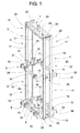
- Fig. 1 shows a catch frame 1 according to the invention for a multi-deck cabin with a lower deck 2 and an upper deck 3.
- the cabin of the lower deck and the cabin of the upper deck are not shown.
- the catch frame 1 forms a cuboid and consists of a first side plate 4, a second side plate 5, a lower yoke 6 and an upper yoke 7 and is stiffened by a center yoke 9.
- the catch frame 1 carries a lower deck frame 8 for the lower cabin.
- the upper cabin is supported by the center yoke 9.
- adjustable supports 10 are arranged for vibration damping, on which the cabins rest.
- Guiding devices, not shown, are provided on the catch frame 1, for example roller guide shoes which guide the catch frame 1 along guide rails (not shown) arranged in the elevator shaft in the vertical direction.
- the first side shield 4 consists of a first lower shield member 11 and a first upper shield member 12.
- the second side shield 5 consists of a second lower shield member 13 and a second upper shield member 14.
- Each lower shield member 11,13 consists of at least one lower carrier 16, in the illustrated embodiment, there are two carriers 16, wherein each carrier 16 of the lower shield member 11,13 is connected by means of a connecting means 15 with the corresponding upper carrier 17 of the upper shield member 12,14.
- a carrier 16,17 can be used for example steel used in steel bars with square profile or U-profile.
- the lower deck frame 8 consists of the supports 10 supporting lower side rails 18 and from the carrier 16 of The lower cross member 19 are in communication with the side plates 4,5 and with the lower Jochlinin 22 of the lower yoke 6.
- the middle yoke 9 consists of the bearing 10 supporting upper side rails 20 and from the carrier 17 of the upper shield members 12,14 connecting upper cross members 21, wherein the connecting means 15 engage the upper cross member 21.
- a side member 18,20 can be used for example used in steel bar goods with rectangular profile.
- As a cross member 19,21 and as a lower Jochthere 22 used for example in steel construction can be used with U-profile.
- the side plates 4,5 are above in communication with the upper yoke 7, wherein upper Jochlini 22 and webs 23 form the upper yoke 7.
- a 1: 1 support means guide the catch frame 1 is supported by the upper yoke 7 attacking Tragstoffendtheticen 24. It is conceivable even with a 2: 1 support means guide, the support means via at least one arranged on the upper yoke 7 pulley or at least two below the upper deck. 3 to guide the catch frame 1 arranged or arranged on the lower yoke 6 pulleys.
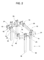
- Fig. 2 shows the lower shield members 11,13 with the center yoke 9.
- a connecting means 15 is arranged, which is also in communication with the Mittenjoch 9.
- the upper shield parts 12,14 which also communicate with the connecting device, not shown.
- an adjusting device 25 is provided at each upper cross member 21 of the middle yoke 9, by means of the catch frame 1 during assembly relative to the respective guide rail can be aligned.
- the lower cross member 19 and each web 23 an adjusting device 25 is also provided.
- Each support 10 is designed to be displaceable along its longitudinal member 20 and is also suitable for receiving a load-measuring sensor.
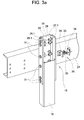
- Fig. 3 shows details of the connecting device 15 seen from the guide rail ago.
- the lower carrier 16 with square profile is comprised of a first angle section 26 and a second angle section 27 on three sides. Each opposite leg of the angle sections 26,27 is associated with a flat profile 28,29. The equal legs is assigned a common flat profile 30.
- the flat profiles 28,29,30 are arranged in the lower carrier 16 and on the inner sides of the square profile. Not shown is the lower end of the upper support 17.
- the lower end of the upper support 17 is arranged as the upper end of the lower support 16 between the angle sections 26,27 and the flat sections 28,29,30.
- Angle profiles 26,27, flat profiles 28,29,30, screws 31 and nuts 32 connect the two carriers 16,17 to a from the lower yoke 6 to the upper yoke 7 reaching carrier as part of the side plate 4,5.
- Fig. 3a shows instead of the angle profiles 26,27 flat profiles 26.1,27.1.
- a guide rail consists of a rail foot and a free guide leg, the rail foot is firmly connected to the shaft wall or a console.
- the catch frame 1 is aligned per side plate 4.5 by means of the adjusting device 25 for the free guide leg of the guide rail, wherein an adjustment head 33 is provided on each side of the free guide leg is.
- Each adjusting head 33 is arranged on a bracket 34, wherein the adjusting head 33 is seen in the longitudinal axis adjustable.
- Fig. 4 shows details of the connecting device 15 seen from the middle yoke 9 ago. To simplify the assembly, a support 35 is incorporated, which serves as a support and stop for the upper cross member 21.
- Fig. 4a shows instead of the angle profiles 26,27 flat profiles 26.1,27.1.
- each side plate can be divided into more than two shield parts.
- a shield part can also consist of one or more than two carriers.
- the Mittenjoch can also be used in catch frames with one-piece side plates. Catching frames with more than one Mittenjoch are also conceivable.
Landscapes
- Engineering & Computer Science (AREA)
- Civil Engineering (AREA)
- Mechanical Engineering (AREA)
- Structural Engineering (AREA)
- Lift-Guide Devices, And Elevator Ropes And Cables (AREA)
- Cage And Drive Apparatuses For Elevators (AREA)
Priority Applications (2)
| Application Number | Priority Date | Filing Date | Title |
|---|---|---|---|
| EP07103743A EP1967480A1 (fr) | 2007-03-08 | 2007-03-08 | Cadre pour cabine avec plusieurs compartiments |
| CNA2008101737467A CN101381051A (zh) | 2007-03-08 | 2008-03-07 | 多层轿厢的支承架 |
Applications Claiming Priority (1)
| Application Number | Priority Date | Filing Date | Title |
|---|---|---|---|
| EP07103743A EP1967480A1 (fr) | 2007-03-08 | 2007-03-08 | Cadre pour cabine avec plusieurs compartiments |
Publications (1)
| Publication Number | Publication Date |
|---|---|
| EP1967480A1 true EP1967480A1 (fr) | 2008-09-10 |
Family
ID=38335725
Family Applications (1)
| Application Number | Title | Priority Date | Filing Date |
|---|---|---|---|
| EP07103743A Withdrawn EP1967480A1 (fr) | 2007-03-08 | 2007-03-08 | Cadre pour cabine avec plusieurs compartiments |
Country Status (2)
| Country | Link |
|---|---|
| EP (1) | EP1967480A1 (fr) |
| CN (1) | CN101381051A (fr) |
Cited By (2)
| Publication number | Priority date | Publication date | Assignee | Title |
|---|---|---|---|---|
| CN102372215A (zh) * | 2011-09-30 | 2012-03-14 | 快意电梯有限公司 | 一种直角开门的电梯布置结构 |
| CN109849942A (zh) * | 2019-04-18 | 2019-06-07 | 徐州立人单轨运输装备有限公司 | 一种单轨吊乘人装置和矿井单轨吊车 |
Families Citing this family (3)
| Publication number | Priority date | Publication date | Assignee | Title |
|---|---|---|---|---|
| CN102535854B (zh) * | 2012-02-16 | 2015-03-25 | 三一汽车制造有限公司 | 一种爬升支架及其爬升方法、混凝土布料杆及其爬升方法 |
| EP2993152B8 (fr) * | 2014-09-04 | 2017-04-19 | KONE Corporation | Appareil et procédé d'alignement de rails de guidage dans une cage d'ascenseur |
| CN111990156B (zh) * | 2020-09-25 | 2022-02-25 | 南京林业大学 | 一种专用于园林景观的绿化树木支撑装置 |
Citations (3)
| Publication number | Priority date | Publication date | Assignee | Title |
|---|---|---|---|---|
| JPH1017228A (ja) * | 1996-07-03 | 1998-01-20 | Toshiba Corp | ダブルデッキエレベータ |
| JP2001122564A (ja) * | 1999-10-25 | 2001-05-08 | Toshiba Elevator Co Ltd | ダブルデッキエレベーター |
| JP2005206315A (ja) * | 2004-01-22 | 2005-08-04 | Fujitec Co Ltd | エレベータかご |
-
2007
- 2007-03-08 EP EP07103743A patent/EP1967480A1/fr not_active Withdrawn
-
2008
- 2008-03-07 CN CNA2008101737467A patent/CN101381051A/zh active Pending
Patent Citations (3)
| Publication number | Priority date | Publication date | Assignee | Title |
|---|---|---|---|---|
| JPH1017228A (ja) * | 1996-07-03 | 1998-01-20 | Toshiba Corp | ダブルデッキエレベータ |
| JP2001122564A (ja) * | 1999-10-25 | 2001-05-08 | Toshiba Elevator Co Ltd | ダブルデッキエレベーター |
| JP2005206315A (ja) * | 2004-01-22 | 2005-08-04 | Fujitec Co Ltd | エレベータかご |
Cited By (3)
| Publication number | Priority date | Publication date | Assignee | Title |
|---|---|---|---|---|
| CN102372215A (zh) * | 2011-09-30 | 2012-03-14 | 快意电梯有限公司 | 一种直角开门的电梯布置结构 |
| CN109849942A (zh) * | 2019-04-18 | 2019-06-07 | 徐州立人单轨运输装备有限公司 | 一种单轨吊乘人装置和矿井单轨吊车 |
| CN109849942B (zh) * | 2019-04-18 | 2024-04-30 | 徐州立人单轨运输装备有限公司 | 一种单轨吊乘人装置和矿井单轨吊车 |
Also Published As
| Publication number | Publication date |
|---|---|
| CN101381051A (zh) | 2009-03-11 |
Similar Documents
| Publication | Publication Date | Title |
|---|---|---|
| DE69805257T2 (de) | Verfahren und apparatus zum einbau eines aufzugs | |
| DE69808826T2 (de) | Aufzug mit verstellbarem Doppeldeck | |
| WO1999033742A1 (fr) | Ascenseur a cables avec poulie motrice | |
| EP3052420B1 (fr) | Installation d'ascenseur | |
| WO2018234351A1 (fr) | Système d'ascenseur | |
| DE102013110791A1 (de) | Aufzuganlage | |
| EP1489033A1 (fr) | Ascenseur avec deux cabines superposées dans la même cage | |
| EP3119713A1 (fr) | Ascenseur équipé d'un dispositif de tension de câble de compensation | |
| EP4038004B1 (fr) | Cabine pour un ascenseur à double étage | |
| EP1967479A1 (fr) | Cadre pour cabine avec plusieurs compartiments. | |
| EP3176120B1 (fr) | Ascenseur à poulie de traction de type sac à dos | |
| EP3227216A1 (fr) | Installation d'ascenseur | |
| EP1194359B1 (fr) | Systeme d'ascenseur a cable | |
| WO2024141295A1 (fr) | Dispositif pour porter un moteur d'entraînement d'un système d'ascenseur | |
| DE10319731B4 (de) | Aufzug | |
| DE20021886U1 (de) | Treibscheibenaufzug mit einer Aufzugskabine in Rucksack-Bauweise | |
| EP2468674A1 (fr) | Installation d'ascenseur à biplan | |
| DE112016007540T5 (de) | Aufzugsvorrichtung | |
| EP1302432B1 (fr) | Ensemble pour installer la machine d'ascenseur dans la cage | |
| CH436619A (de) | Aufzugsanlage mit Treibscheibenantrieb | |
| EP4406896A1 (fr) | Installation d'ascenseur dotée d'une première cabine d'ascenseur et d'une seconde cabine d'ascenseur | |
| EP2114812A1 (fr) | Guidage par câbles pour un entraînement d'ascenseur | |
| WO2024160610A1 (fr) | Système de levage | |
| EP1321416A1 (fr) | Dispositif pour rails de guidage d'ascenseurs | |
| EP1950168B1 (fr) | Cadre pour ascenseur |
Legal Events
| Date | Code | Title | Description |
|---|---|---|---|
| PUAI | Public reference made under article 153(3) epc to a published international application that has entered the european phase |
Free format text: ORIGINAL CODE: 0009012 |
|
| AK | Designated contracting states |
Kind code of ref document: A1 Designated state(s): AT BE BG CH CY CZ DE DK EE ES FI FR GB GR HU IE IS IT LI LT LU LV MC MT NL PL PT RO SE SI SK TR |
|
| AX | Request for extension of the european patent |
Extension state: AL BA HR MK RS |
|
| AKX | Designation fees paid | ||
| REG | Reference to a national code |
Ref country code: DE Ref legal event code: 8566 |
|
| STAA | Information on the status of an ep patent application or granted ep patent |
Free format text: STATUS: THE APPLICATION IS DEEMED TO BE WITHDRAWN |
|
| 18D | Application deemed to be withdrawn |
Effective date: 20090311 |