EP1967614A2 - Appareil et procédé de conversion d'eau dans un gaz combustible propre à utiliser comme additif à d'autres sortes de combustibles - Google Patents
Appareil et procédé de conversion d'eau dans un gaz combustible propre à utiliser comme additif à d'autres sortes de combustibles Download PDFInfo
- Publication number
- EP1967614A2 EP1967614A2 EP07107267A EP07107267A EP1967614A2 EP 1967614 A2 EP1967614 A2 EP 1967614A2 EP 07107267 A EP07107267 A EP 07107267A EP 07107267 A EP07107267 A EP 07107267A EP 1967614 A2 EP1967614 A2 EP 1967614A2
- Authority
- EP
- European Patent Office
- Prior art keywords
- electrodes
- electrolyzer
- gas
- supplemental
- species
- Prior art date
- Legal status (The legal status is an assumption and is not a legal conclusion. Google has not performed a legal analysis and makes no representation as to the accuracy of the status listed.)
- Withdrawn
Links
Images











Classifications
-
- C—CHEMISTRY; METALLURGY
- C01—INORGANIC CHEMISTRY
- C01B—NON-METALLIC ELEMENTS; COMPOUNDS THEREOF; METALLOIDS OR COMPOUNDS THEREOF NOT COVERED BY SUBCLASS C01C
- C01B3/00—Hydrogen; Gaseous mixtures containing hydrogen; Separation of hydrogen from mixtures containing it; Purification of hydrogen; Reversible storage of hydrogen
-
- C—CHEMISTRY; METALLURGY
- C01—INORGANIC CHEMISTRY
- C01B—NON-METALLIC ELEMENTS; COMPOUNDS THEREOF; METALLOIDS OR COMPOUNDS THEREOF NOT COVERED BY SUBCLASS C01C
- C01B3/00—Hydrogen; Gaseous mixtures containing hydrogen; Separation of hydrogen from mixtures containing it; Purification of hydrogen; Reversible storage of hydrogen
- C01B3/0094—Atomic hydrogen
-
- C—CHEMISTRY; METALLURGY
- C01—INORGANIC CHEMISTRY
- C01B—NON-METALLIC ELEMENTS; COMPOUNDS THEREOF; METALLOIDS OR COMPOUNDS THEREOF NOT COVERED BY SUBCLASS C01C
- C01B5/00—Water
-
- Y—GENERAL TAGGING OF NEW TECHNOLOGICAL DEVELOPMENTS; GENERAL TAGGING OF CROSS-SECTIONAL TECHNOLOGIES SPANNING OVER SEVERAL SECTIONS OF THE IPC; TECHNICAL SUBJECTS COVERED BY FORMER USPC CROSS-REFERENCE ART COLLECTIONS [XRACs] AND DIGESTS
- Y02—TECHNOLOGIES OR APPLICATIONS FOR MITIGATION OR ADAPTATION AGAINST CLIMATE CHANGE
- Y02E—REDUCTION OF GREENHOUSE GAS [GHG] EMISSIONS, RELATED TO ENERGY GENERATION, TRANSMISSION OR DISTRIBUTION
- Y02E60/00—Enabling technologies; Technologies with a potential or indirect contribution to GHG emissions mitigation
- Y02E60/30—Hydrogen technology
- Y02E60/36—Hydrogen production from non-carbon containing sources, e.g. by water electrolysis
Definitions
- This invention is related to equipment or a system and method for the processing of water or distilled water into a gaseous and combustible form of HHO combustible gas produced from water for use in internal combustion engine systems, in other fossil fuel engine systems, in gaseous welding systems and other similar systems.
- the invention is also related to the form of HHO combustible gas produced from electrolyzers or gas generators connected to such systems.
- the novelty of the present invention over preceding prior art is clear and distinct.
- the prior art deals with equipment and methods for the processing of water into conventional gaseous fuels, that is, fuels possessing the conventional molecular chemical composition or mixture of chemical compositions and is sometimes referred to as "Brown's Gas".
- the present invention provides equipment or a system and related processes (methodology) to produce novel fuel composed of a chemical species beyond that of molecules, that is, HHO combustible gas, which fuel is produced from water using a particular form of electrolyzer.
- This invention deals with the structure, properties and initial applications of a new clean burning combustible gas hereinafter called "HHO gas” produced from distilled water using a special electrolyzer described in detail in the Specifications.
- HHO gas a new clean burning combustible gas
- the HHO gas is dramatically different than the Brown gas or other gases produced by pre-existing electrolyzers.
- the latter is a combination of conventional hydrogen and conventional oxygen gases, that is, gases possessing the conventional "molecular" structure, having the exact stochiometric ratio of 2/3 hydrogen and 1/3 oxygen.
- the HHO gas does not have such an exact stochiometric ratio but instead has basically a structure having a "magnecular" characteristic, including the presence of clusters in macroscopic percentages that cannot be explained via the usual valence bond.
- the constituents clusters of the Brown Gas and the HHO gas are dramatically different both in percentages as well as in chemical composition, as shown below.
- the first remarkable feature of the special electrolyzers of this invention is their efficiencies. For example, with the use of only 4 Kwh, an electrolyzer rapidly converts water into 55 standard cubic feet (scf) of HHO gas at 35 pounds per square inch (psi). By using the average daily cost of electricity at the rate of $0.08/Kwh, the above efficiency implies the direct cost of the HHO gas of $0.007/scf. It then follows that the HHO gas is cost competitive with respect to existing fuels.
- the HHO gas results to be odorless, colorless and lighter than air.
- a first basic feature in the production of the HHO gas is that there is no evaporation of water at all, and water is directly transmuted into the HHO gas. In any case, the electric energy available in the electrolyzer is basically insufficient for water evaporation.
- the second important feature of the HHO gas is that it exhibits a "widely varying energy content" in British Thermal Units (BTU), ranging from a relatively cold flame in open air, to large releases of thermal energy depending on its use. This is a direct evidence of fundamental novelty in the chemical structure of the HHO gas.
- BTU British Thermal Units
- the third important feature of the HHO gas is that it does not require any oxygen for its combustion since it contains in its interior all oxygen needed for that scope.
- the fourth important feature of the HHO gas is its anomalous adhesion to gases, liquids and solids, as verified experimentally below, thus rendering its use particularly effective as an additive for the enhancement of desired qualities.
- the fifth important feature of the HHO gas is that it does not follow the fundamental PVT law of all conventional gases (namely, those with molecular structure), since the HHO gas begins to deviate from this law at around 150 psi, and it reacquires the water state at a sufficiently high pressures beginning with 250 psi. These aspects are further being investigated for possible development and commercial exploitation.
- the sixth important feature of the HHO gas is that it bonds to gaseous fuels (such as natural gas, magnegas fuel, and other fuels) and liquid fuels (such as diesel, gasoline, liquid petroleum, and other fuels) by significantly improving their thermal content as well as the environmental quality of their exhaust.
- gaseous fuels such as natural gas, magnegas fuel, and other fuels
- liquid fuels such as diesel, gasoline, liquid petroleum, and other fuels
- the seventh and most important feature of the HHO gas is that it melts almost instantaneously tungsten, bricks, and other highly refractive substances.
- measurements have established the remarkable capability by the HHO gas of reaching almost instantaneously temperatures up to 9,000 degrees C, namely a temperature of the order of that in the Sun chromosphere under which all substances on Earth can be sublimated.
- This invention also involves an electrolyzer for the separation of water, which includes, in one embodiment an electrolysis chamber; an aqueous electrolytic solution comprising water and electrolyte, the aqueous electrolyte solution partially filling the electrolysis chamber such that a gas reservoir region is formed above the aqueous electrolyte solution; two principal electrodes comprising an anode electrode and a cathode electrode, the two principal electrodes being at least partially immersed in the aqueous electrolyte solution; one or more supplemental electrodes at least partially immersed in the aqueous electrolyte solution and interposed between the two principal electrodes wherein the two principal electrodes and the one or more supplemental electrodes are held in a fixed spatial relationship; wherein said electrolyzer produces a combustible gas composed of hydrogen and oxygen atoms and their bonds into chemical species caused by electrons valence bonds and the bond due to attractive forces between opposing magnetic polarities originating in the toroidal polarization of the electron orbitals.
- the relatively simple design of the electrodes -- as rectangular or square metallic flat shapes as shown in Fig. 19 allows for the electrodes to be easily replaced.
- This oxy-hydric combustible gas is collected in the gas reservoir region, which is adapted to deliver the gas to the fuel system of an internal combustion engine.
- the invention can be used to improve the fuel efficiency of an internal combustion engine.
- the method comprises using any of the embodiments of the electrolyzers disclosed herein in conjunction with an internal combustion engine.
- An electrical potential is applied to the electrodes of the electrolyzer thereby caused the electrolyzer to generate the gas.
- the gas is then combined with the fuel in the fuel system of the internal combustion engine before the fuel is combusted in the internal combustion engine.
- an electrolyzer in still another embodiment, includes an electrolysis chamber which holds an electrolyte solution.
- the electrolysis chamber mates with a cover at a flange.
- there is a seal between the chamber and cover which is made from a neoprene gasket, which is placed between the flange and cover.
- the electrolyte solution may be an aqueous electrolyte solution to produce a mixture of the novel gases; however, to produce the novel inventive gases, distilled water preferably is used.
- the electrolyte partially fills the electrolysis chamber during operation to level such that gas reservoir region is formed above the electrolyte solution.
- the electrolyzer includes two principal electrodes - anode electrode and cathode electrode- which are at least partially immersed in the electrolyte solution.
- Anode electrode and cathode electrode slip into grooves in a rack.
- the rack is placed inside the chamber.
- One or more supplemental electrodes are also placed in the rack. Again, the supplemental electrodes are at least partially immersed in the aqueous electrolyte solution and interposed between the anode electrode and cathode electrode.
- anode electrode, cathode electrode, and supplemental electrodes are held in a fixed spatial relationship by rack.
- anode electrode, cathode electrode, and supplemental electrodes are separated by a distance of about 0.25 inches.
- the one or more supplemental electrodes allow for enhanced and efficient generation of this gas mixture.
- the two principal electrodes are each individually a metallic wire mesh, a metallic plate, or a metallic plate having one or more holes. More preferably, the two principal electrodes are each individually a metallic plate.
- a suitable metal from which the two principal electrodes are formed includes but is not limited to, nickel, nickel containing alloys, and stainless steel.
- the preferred metal for the two electrodes is nickel.
- the one or more supplemental electrodes are preferably a metallic wire mesh, a metallic plate, or a metallic plate having one or more holes or as further described below. More preferably, the one or more supplemental electrodes are each individually a metallic plate.
- a suitable metal from which the supplemental electrodes are formed includes but is not limited to, nickel, nickel containing alloys, stainless steel and/or foam based material as described below.
- the supplemental electrodes may be made from a high porosity foam based material made substantially of a nickel material (preferably greater than 99% nickel in a foam material where the high porosity electrode results in a composite lattice-like configured electrode due to the use of foam and nickel fibers or powder).
- a nickel material preferably greater than 99% nickel in a foam material where the high porosity electrode results in a composite lattice-like configured electrode due to the use of foam and nickel fibers or powder.
- Such material for the electrodes can be obtained as INCO® Nickel Foam, C.A.S. No. 7440-02-0 from Inco Special Products in Wyckoff, New Jersey.
- the nickel content of this product can vary between 25% and 85% with densities ranging from 1.0 to 2.70 g/cc.
- a nickel content of greater than 99% nickel in the foam plate and about 14% nickel in the stainless steel plates provides for excellent results in producing the novel oxy-hydric combustible gas.
- the supplemental electrodes can further be configured so that one of the adjacent supplemental electrodes is made from the foam material and the opposing supplemental electrode is made substantially of a stainless steel material, wherein said supplemental electrodes results in a (+) and (-) electrical (ionic) current flow that causes the formation of a single combustible gas over an entire surface area of both sides of all electrodes within the electrolyzer.
- Other configurations of electrodes are permissible; however, the above configuration has been found to be very effective in producing the desired oxy-hydric gas.
- a voltage is applied between the anode electrode and cathode electrode which causes the novel gas to be produced and which collects in a gas reservoir region.
- the gaseous mixture exits the gas reservoir region from through an exit port and ultimately is fed into the fuel system of an internal combustion engine.
- An electrical contact to anode electrode is made through a contactor and electrical contact to cathode electrode is made by another contactor.
- the contactors are preferably made from metal and are slotted with channels such that the contactors fit over the anode electrode and cathode electrode.
- the contactors are attached to rods, which slip through holes in the cover. Preferable the holes are threaded and the rods are threaded rods so that rods screw into the holes.
- the contactors also hold the rack in place since the anode electrode and cathode electrode are held in place by channels and by grooves in the rack. Accordingly, when the cover is bolted to the chamber, the rack is held at the bottom of the chamber.
- the electrolyzer optionally includes a pressure relief valve and a level sensor.
- the pressure relief valve allows the gaseous mixture in the gas reservoir to be vented before a dangerous pressure buildup can be formed.
- the level sensor ensures that an alert is sounded and the flow of gas to the vehicle fuel system is stopped when the electrolyte solution gets too low. At such time when the electrolyte solution is low, addition electrolyte solution is added through a water fill port.
- the electrolyzer may also include a pressure gauge so that the pressure in the reservoir may be monitored.
- the electrolyzer optionally includes one or more fins which remove heat from the electrolyzer.
- a first group of the one or more supplemental electrodes is connected to the anode electrode with a first metallic conductor and a second group of the one or more supplemental electrodes is connected to the cathode electrode with a second metallic conductor.
- the anode electrode, cathode electrode, and supplemental electrodes are held to the rack by a holder rod, which slips through channels in the rack and the holes in the electrodes.
- the rack is preferably fabricated from a high dielectric plastic such as PVC, polyethylene or polypropylene. Furthermore, the rack holds the anode electrode, cathode electrode, and supplemental electrodes in a fixed spatial relationship.
- the fixed spatial relationship of the two principal electrodes and the one or more supplemental electrodes is such that the electrodes (two principal and one or more supplemental) are essentially parallel and each electrode is separated from an adjacent electrode by a distance from about 0.15 to about 0.35 inches. More preferably, each electrode is separated from an adjacent electrode by a distance from about 0.2 to about 0.3 inches, and most preferably about 0.25 inches.
- the fixed spatial relationship is accomplished by a rack that holds the two principal electrodes and the one or more supplemental electrodes in the fixed spatial relationship. The electrodes sit in grooves in the rack which define the separations between each electrode. Furthermore, the electrodes are removable from the rack so that the electrodes or the rack may be changed if necessary. Finally, since the rack and anode electrode and cathode electrode are held in place as set forth above, the supplemental electrodes are also held in place because they are secured to the rack by the holder rod.
- the novel combustible gas is formed by the electrolysis of the electrolyte solution in the electrolyzer.
- the electrolyzer is connected to a collection tank by a pressure line.
- the gases are collected and temporarily stored in the collection tank.
- the collection tank optionally includes a pressure relief valve to guard against any dangerous pressure build up.
- the collection tank is connected to a solenoid by a pressure line.
- the solenoid is in turn connected by a pressure line to an engine intake manifold.
- a flash arrestor is incorporated in the pressure line to prevent a flame from propagating in a tube.
- a pressure line also includes an orifice to regulate the flow of the gaseous mixture into the intake manifold. The size of this orifice will depend on the size of the engine.
- an orifice diameter of about 0.04 is suitable for a 1 liter engine, about 0.06 inches is suitable for a 2.5 liter engine, and about 0.075 inches is suitable for a V8 engine.
- the applied voltage to the electrolyzer is provided through the solenoid by an electrolyzer battery.
- solenoid switches and a voltage of about 12 V is applied between the anode electrode and cathode electrode.
- a battery isolator allows for charging of a vehicle battery and electrolyzer battery by an alternator while keeping the electrolyzer battery and vehicle battery electrically isolated.
- the solenoid is powered by the vehicle battery when the main switch is activated.
- a gas mixer solenoid is also powered by the vehicle battery and opens when the gas mixture is provided to the intake manifold.
- the solenoid also receives a feedback from the level sensor which causes the solenoid to shut off the gas flow if the electrolyte solution level in the electrolyzer gets too low.
- the operation of the vehicle's oxygen sensor needs to be adjusted to take into account the additional oxygen that is added to the fuel system from the electrolyzer. Normally, if the oxygen sensor senses more oxygen, the vehicle's computer would determine that the engine is running lean and open up the fuel injectors to a richer fuel mixture. This is undesirable and would cause poor fuel economy.
- a method for increasing the fuel efficiency of an internal combustion engine utilizes the electrolyzer described above in conjunction with an internal combustion engine.
- the method comprises providing an electrolyzer equipment described above or as further described below in other novel embodiments; applying an electrical potential between the electrodes wherein the novel combustible gas described herein is generated and collected in the gas reservoir region and wherein the electrolyzer is adapted to deliver the combustible gas to the fuel system of an internal combustion engine; and combining the combustible gas produced with fuel in the fuel system of an internal combustion engine.
- the step of adjusting the operation of an oxygen sensor as set forth above is also provided.
- an electrolyzer or gas generator is incorporated into a welding/cutting torch system or another type of equipment/engine system.
- This system comprises an electrolyte reservoir, having a top and a bottom, containing electrolytic fluid therein.
- the fluid herein is preferably water.
- the electrolyte reservoir comprises a broken or permeable plate, which is sealably and circumferentially positioned around a top end of the electrolyte reservoir. Plate functions to release gas pressure within the electrolyte reservoir when exceeding a pre-determined safety level.
- the self-producing hydrogen and oxygen gas generating system further comprises a pump, preferably an electromagnetic pump, which is connected at one distal end to the bottom of the electrolyte reservoir.
- Pump is connected at an opposite distal end to at least one hydrogen and oxygen electrolyzer/generator containing an electrical conductor therein.
- the electrical conductor is electrically connected on one distal end to an electrical ground.
- the opposite distal end of the electrical conductor is electrically connected to one distal end of a pressure controller.
- the opposite distal end of the electrical conductor is electrically connected to a power source.
- Pump functions to circulate electrolytic fluid from the electrolyte reservoir through at least one hydrogen and oxygen electrolyzer/generator through a radiator back into the electrolyte reservoir via a gas pipe.
- the radiator functions to cool the generated hydrogen and oxygen gas before returning to the electrolyte reservoir.
- the pressure controller is connected to the electrolyte reservoir and monitors the pressure therein.
- gas pressure within the electrolyte reservoir exceeds a pre-determined level, electrical current is terminated to the electrical conductor contained within the hydrogen and oxygen generator thereby ceasing production of hydrogen and oxygen gas.
- gas pressure within the electrolyte reservoir drops below a pre-determined level, electrical current is connected to the electrical conductor contained within the hydrogen and oxygen generator thereby commencing production of hydrogen and oxygen gas.
- the pre-selected level is less than the pre-selected level required to cause a pressure release through plate.
- This self-producing on-demand hydrogen and oxygen generating system further comprises a non-return valve connected at one end to an upper end of the electrolyte reservoir below plate.
- the non-return valve is further connected to a dryer/filter means or tank at an opposite distal end.
- System further comprises another filter/dryer means or tank in fluid communication with one end of the electrolyte reservoir above plate and further connected at an opposite distal end to another non-return valve via gas line, which is connected at an opposite end to another filter/dryer means or tank.
- System further comprises a decompression valve in fluid communication at one end to the top end of the electrolyte reservoir and further being in fluid communication with the gas pipe, which in turn is connected to radiator.
- the welding system further comprises a microprocessor controlled D.C. amperage regulator adapted to regulate the D.C. amperage from the power source to the hydrogen and oxygen generator.
- a first microprocessor controlled cut-off switch is adapted to terminate the power source to the welder in response to a malfunction of the pump.
- a second microprocessor controlled cut-off switch is adapted to terminate the power source to the welder in response to an insufficient electrolyte solution condition within the electrolyte reservoir.
- a microprocessor controlled liquid crystal display is adapted to display operating statistics regarding the welding system, such statistics to include hours of operation, amperage, indicator lights and pressure gauge readings. The liquid crystal display receives input from a plurality of locations within the system.
- a microprocessor controlled polarity change system is adapted to change the polarity of the electrical conductor located within the hydrogen and oxygen generator.
- a microprocessor controlled cool-down system is adapted to operate a generator fan and the pump wherein operation of the fan and the pump continue throughout a cool-down stage following manual shut-off of the welder.
- the produced gas or HHO gas is routed from the dryer means to the final gas reservoir tank. Dryer means and are only exemplary. It is understood that a single unit may be designed to effectively accomplish the same objective.
- the gas is then supplied on-demand to the engine or in this case, the welding equipment, through gas line and hydrogen flash suppressor check valve (non-return valve) and control valve.
- a flame from said produced gas or species of hydrogen and oxygen, from said electrolyzer can instantly melt solids without the use of atmospheric oxygen.
- the produced gas can also be used as a fuel without the use of atmospheric oxygen, and can bond to other substances via magnetic induction.
- a bond is created between a fossil fuel and a combustible gas composed by a combination of hydrogen and oxygen atoms with toroidal polarization of their orbitals.
- the bond originates from the induced magnetic polarization of at least some of the orbitals of said fuel and the consequential attraction between opposing magnetic polarities.
- the combustion exhaust of the resulting fuel is cleaner than that of said fossil fuels. Further, the resulting fuel has contained more thermal energy than that of said fossil fuels.
- HHO gas originates from distilled water using a special electrolytic process described hereinafter, it is generally believed that such a gas is composed of 2/3 (or 66.66% in volume) hydrogen H2 and 1/2 (or 33.33% in volume) oxygen O2.
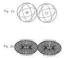
- HHO contains not only "atomic hydrogen” (that is, individual H atoms without valence bond to other atoms as in Figure 1a ), but also "magnetically polarized atomic hydrogen", that is, hydrogen atoms whose electrons are polarized to rotate in a toroid, rather than in all space directions, as per Figure 1b .
- the dimension of the H2 molecules caused by thermal rotations are such to prevent a rapid penetration of hydrogen within deeper layers of tungsten or bricks, thus preventing their rapid melting.
- the only know configuration of the hydrogen molecule compatible with the above outlined physical and chemical evidence is that the molecule itself is polarized with its orbitals restricted to rotate in the oo-shaped toroid of Figure 2b .
- polarized hydrogen atoms as in Figure 1b and polarized hydrogen molecules as in Figure 2b are sufficiently thin to have a rapid penetration within deeper layers of substances.
- the magnetic field created by the rotation of electrons within toroids is such so as to polarize the orbitals of substances when in close proximity, due to magnetic induction.
- the polarized orbitals of tungsten and bricks are essentially at rest. Therefore, magnetic induction causes a natural process of rapid self-propulsion of polarized hydrogen atoms and molecules deep within substances.
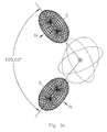
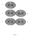
- the central feature of this invention is, therefore, that the special electrolyzer of this invention is such to permit the transformation of the water molecule from the conventional H-O-H configuration of Figure 3a to the basically novel configuration of Figure 3b , which latter configuration is, again, permitted by the fact that, in the absence of electric polarization, the attraction between opposite magnetic polarities of the toroidal distributions of the orbitals is much stronger than the Coulomb repulsion due to charges.
- H-O-H Figure 3a
- HxH-O Figure 3b
- a central feature of this invention is that the transition from the H-O-H configuration to the new HxH-O one is essentially caused by the two H atoms establishing an "internal hydrogen bridge,” rather than the usual "external bridge with other H atoms.
- the first fundamental point is the precise identification of the "physical origin of the attractive force” as well as its “numerical value,” without which science is reduced to a mere political nomenclature.
- a first most important experimental verification of this invention is that the removal of the electric polarization of the water molecule, with consequential transition from the H-O-H to the new HxH-O configuration, can indeed be achieved via the minimal energy available in the electrolyzer and absolutely without the large amount of energy needed for water evaporation.
- the new chemical species HxH is another central novelty of this invention inasmuch as it contains precisely the polarized atomic hydrogen needed to explain physical and chemical evidence recalled earlier, the remarkable aspect being that these polarizations are set by nature in the water molecule, and mainly brought to a useful form by the inventive electrolyzer.
- the hydrogen content of the HHO gas is predicted to be given by a mixture of HxH and H-H that, under certain conditions, can be 50%-50%.
- the H-H molecule has a weight of 2 atomic mass units (amu).
- the bond in HxH is much weaker than the valence bond of H-H. Therefore, the species HxH is predicted to be heavier than the conventional one H-H (because the binding energy is negative). However, such a difference is of the order of a small fraction of one amu, thus being beyond the detecting abilities of currently available analytic instruments solely based on mass detection. It ten follows that the species HxH and H-H will appear to be identical under conventional mass spectrographic measurements since both will result to have the mass of 2 amu.
- the situation for the oxygen atom following its separation in the H-O-H molecule is essentially similar to that of hydrogen.
- the orbitals of its two valence electrons are not distributed in all directions in space, but have a polarization into toroids parallel to the corresponding polarizations of the H atoms.
- the oxygen contained in the HHO gas is initially composed of the new magnecular species OxO, that also has a 50% probability of converting into the conventional molecular species O-O, resulting in a mixture of OxO and O-O according to proportions that can be, under certain conditions, 50%-50%.
- the O-O species has the mass of 32 amu.
- the new species OxO has a mass bigger than 32 amu due to the decrease in absolute value of the binding energy (that is negative) and the consequential increase of the mass.
- the mass increase is of a fraction of one amu, thus not being detectable with currently available mass spectrometers.
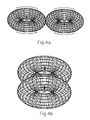
- HHO gas cannot be solely composed of the above identified mixture of HxH/H-H and OxO/O-O gases and numerous additional species are possible. This is due to the fact that, valence bonds ends when all valence electrons are used, in which case no additional atom can be added. On the contrary, magnecular bonds such as that of the HxH structure of Figure 4b have no limit in the number of constituents, other than the limits sets forth by temperature and pressure.
- the next species predicted in the HHO gas has 17 amu and consists of the magnecule HxO that also has a 50% transition probability to the conventional radical H-O. Detectable traces of this species are expected because they occur in all separations of water.
- the next species expected in the HHO gas has the mass of 18 amu and it is given by the new magnecular configuration of the water HxH-O of Figure 3b .
- the distinction between this species and the conventional water molecule H-O-H at the vapor state can be easily established via infrared and other detectors.
- the next species expected in the HHO gas has the mass of 19 amu and it is given by traces the magnecule HxH-O-H or HxH-O-H. A more probable species has the mass of 20 amu with structure HxH-O-HxH.
- the HHO combustible gas is composed of hydrogen and oxygen atoms bonded into clusters H m O n in which m and n have integer values with the exclusion of the case in which both m and n are zero.
- the released value of 12.3 grams per mole is anomalous.
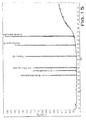
- Adsorption Research Laboratory also conducted gas chromatographic scans of the HHO gas reproduced in Figure 6 confirming most of the predicted constituents of this invention. In fact, the scans of Figure 6 confirm the presence in the HHO gas of the following species here presented in order of their decreasing percentages:
- the first anomaly of HHO is that of showing comparatively much stronger resonating peaks. Therefore, the enclosed IR scan of HHO first establish that the HHO gas has an asymmetric structure, that is a rather remarkable feature since the same feature is absence for the presumed mixture if H2 and O2 gases.
- H2 and O2 gases can have at most two resonating frequencies each, under infrared spectroscopy, one for the vibrations and the other for rotations.
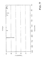
- Spherical distributions of orbitals and other features imply that H2 has essentially only one dominant IR signature as confirmed by the scan of Figure 7 , while O2 has one vibrational IR frequency and three rotational ones, as also confirmed by the scans of Figure 8 .
- the inspection of the IR scans for the HHO gas in Figure 9 reveals additional novelties of this invention.
- First the HHO scan reveals the presence of at least nine different IR frequencies grouped around wavenumber 3000 plus a separate distinct one at around wavenumber 1500.
- the water vapor with molecules H-O-H has IR frequencies with wavelengths 3756, 3657, 1595, their combination and their harmonics (here ignored for simplicity).
- the scan for the HHO gas in Figure 7 confirms the presence of an IR signature near 1595, thus confirming the molecular bond H-O in the magnecular structure HxH-O, but the scan shows no presence of the additional very strong signatures of the water molecules at 3756 and 3657, thus establishing the fact that the peak at 18 amu is not water as conventionally understood in chemistry.
- the measurements were conducted via a Total Ion Chromatogram (TIC) via Gas Chromatography Mass Spectrometry GC-MS manufactures by Hewlett Packard with GC model 5890 series II and MS model 5972.
- the TIC was obtained via a Simulated Distillation by Gas Chromatography (SDGC).
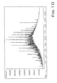
- the used column was a HP 5MS 30 x 0.25 mm; the carrier flow was provided by Helium at 50 degrees C and 5 psi; the initial temperature of the injection was 50 degrees C with a temperature increase of 15 degrees C per minute and the final temperature of 275 degrees C.
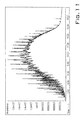
- the chromatogram of Figure 10 confirmed the typical pattern, elusion time and other feature of commercially available diesel. However, the chromatograph of the same diesel with the HHO gas bubbled in its interior of Figure 11 shows large structural differences with the preceding scan, including a much stronger response, a bigger elusion time and, above all, a shift of the peaks toward bigger amu values.
- the latter measurements provide additional confirmation of the existence of a bond between the diesel and the HHO gas, precisely as predicted by the anomalous value of the flash point.
- a bond between a gas and a liquid cannot possibly be of valence type, but can indeed be of magnetic type via induced magnetic polarization of the diesel molecules and consequential bond with the HHO magnecules.
- Figure 15 depicts the anomalous blank of the detector since it shows residual substances following the removal of the gas.
- the blank following the removal of the HHO gas is anomalous because it shows the preservation of the peaks of the preceding scans, an occurrence solely explained by the magnetic polarization of species and their consequential adhesion to the interior of the instrument via magnetic induction.
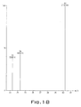
- the Scan of Figure 16 confirms the presence in HHO of the basic species with 2 amu representing H-H and HxH, although their separation was not possible in the Clarus 500 GC-MS.
- the same instrument also cannot detect isolated hydrogen atoms due to insufficient ionization.
- the species with 4 amu representing H-HxH-H could not be detected because helium was the carrier gas and the peak at 4 amu had been subtracted in the scan of Figure 16 . Note however the presence of a clean species with 5 amu that can only be interpreted as H-HxH-HxH.
- the scan of Figure 17 provides clear evidence of a species with mass 16 amu that confirms the presence in HHO of isolated atomic oxygen, thus providing an indirect confirmation of the additional presence of isolated hydrogen atoms due to the impossibility of their detection in the instrument.
- the same scan of Figure 17 confirms the presence in HHO of the species H-O with 17 amu and the species with 18 amu consisting of H-O-H and HxH-O, whose separation is not possible in the instrument here considered.
- the test also confirmed the "blank anomaly" typical of all gases with magnecular structure, namely, the fact that the blank of the instrument following the removal of the gas continues to detect the basic species, which scan is not reproduced here for simplicity, thus confirming the anomalous adhesion of the latter to the instrument walls that can only be explained via magnetic polarization.
- electrolyzer refers to an apparatus that produces chemical changes by passage of an electric current through an electrolyte.
- the electric current is typically passed through the electrolyte by applying a voltage between a cathode and anode immersed in the electrolyte.
- electrolyzer is equivalent to electrolytic cell.
- cathode refers to the negative terminal or electrode of an electrolytic cell or electrolyzer. Reduction typically occurs at the cathode.
- anode refers to the positive terminal or electrode of an electrolytic cell or electrolyzer. Oxidation typically occurs at the anode.
- electrolytes refers to a substance that when dissolved in a suitable solvent or when fused becomes an ionic conductor. Electrolytes are used in the electrolyzer to conduct electricity between the anode and cathode.
- internal combustion engine refers to any engine in which a fuel-air mixture is burned within the engine itself so that the hot gaseous products of combustion act directly on the surfaces of engine's moving parts.
- moving parts include, but are not limited to, pistons or turbine rotor blades.
- Internal-combustion engines include gasoline engines, diesel engines, gas turbine engines, jet engines, and rocket engines.
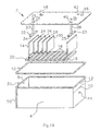
- Electrolyzer 2 includes electrolysis chamber 4 which holds an electrolyte solution. Electrolysis chamber 4 mates with cover 6 at flange 8. Preferably, a seal between chamber 4 and cover 6 is made by neoprene gasket 10 which is placed between flange 8 and cover 6.
- the electrolyte solution may be an aqueous electrolyte solution of water and an electrolyte to produce a mixture of the novel gases; however, to produce the novel inventive gases, distilled water preferably is used.
- Electrolyzer 2 includes two principal electrodes - anode electrode 14 and cathode electrode 16 - which are at least partially immersed in the electrolyte solution.
- Anode electrode 14 and cathode electrode 16 slip into grooves 18 in rack 20.
- Rack 20 is placed inside chamber 4.
- One or more supplemental electrodes 24, 26, 28, 30 are also placed in rack 16 (not all the possible supplemental electrodes are illustrated in Figure 19 .) Again, supplemental electrodes 24, 26, 28, 30 are at least partially immersed in the aqueous electrolyte solution and interposed between the anode electrode14 and cathode electrode 16.
- anode electrode14, cathode electrode 16, and supplemental electrodes 24, 26, 28, 30 are held in a fixed spatial relationship by rack 20.
- anode electrode14, cathode electrode 16, and supplemental electrodes 24, 26, 28, 30 are separated by a distance of about 0.25 inches.
- the electrodes need not be flat, as depicted in Fig. 19 , the electrodes are typically made of a generally flat material.
- the one or more supplemental electrodes allow for enhanced and efficient generation of this gas mixture.
- the two principal electrodes are each individually a metallic wire mesh, a metallic plate, or a metallic plate having one or more holes. More preferably, the two principal electrodes are each individually a metallic plate.
- a suitable metal from which the two principal electrodes are formed includes but is not limited to, nickel, nickel containing alloys, and stainless steel. The preferred metal for the two electrodes is nickel.
- the one or more supplemental electrodes are preferably a metallic wire mesh, a metallic plate, or a metallic plate having one or more holes. More preferably, the one or more supplemental electrodes are each individually a metallic plate.
- a suitable metal from which the supplemental electrodes are formed includes but is not limited to, nickel, nickel containing alloys, stainless steel and foam based material as described above in the summary of the invention section.
- a voltage is applied between anode electrode 14 and cathode electrode 16 which causes the novel gas to be produced and which collects in gas reservoir region 12.
- the gaseous mixture exits gas reservoir region 12 from through exit port 31 and ultimately is fed into the fuel system of an internal combustion engine.
- Electrical contact to anode electrode 14 is made through contactor 32 and electrical contact to cathode electrode 16 is made by contactor 33.
- Contactors 32 and 33 are preferably made from metal and are slotted with channels 34, 35 such that contactors 32, 33 fit over anode electrode 14 and cathode electrode 16.
- Contactor 32 is attached to rod 37 which slips through hole 36 in cover 6.
- contactor 33 is attached to rod 38 which slips through hole 40 in cover 6.
- Electrolyzer 2 optionally includes pressure relief valve 42 and level sensor 44. Pressure relief 42 valve allows the gaseous mixture in the gas reservoir to be vented before a dangerous pressure buildup can be formed.
- Level sensor 44 ensures that an alert is sounded and the flow of gas to the vehicle fuel system is stopped when the electrolyte solution gets too low. At such time when the electrolyte solution is low, addition electrolyte solution is added through water fill port 46. Electrolyzer 2 may also include pressure gauge 48 so that the pressure in reservoir 4 may be monitored. Finally, electrolyzer 2 optionally includes one or more fins 50 that serve as an external heat sink, which removes heat from electrolyzer 2. As can be surmised from Fig. 19 and the above description, the electrolyzer described above is used in a closed or pressurized system under a suitable working pressure for the lines and components connected to the electrolyzer.
- a variation of an electrolyzer is provided.
- the supplemental electrodes are not electrically connected to each other. Power is to the anode and cathode only respectively.
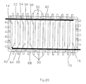
- a first group of the one or more supplemental electrodes 52, 54, 56, 58 is connected to anode electrode 14 with a first metallic conductor 70 and a second group of the one or more supplemental electrodes 62, 64, 66, 68 is connected to cathode electrode 16 with second metallic conductor 60.
- a first group of the one or more supplemental electrodes 52, 54, 56, 58 is connected to anode electrode 14 with a first metallic conductor 70 and a second group of the one or more supplemental electrodes 62, 64, 66, 68 is connected to cathode electrode 16 with second metallic conductor 60.
- the supplemental electrodes may be made from the foam based material described above as well and further, the configuration may be similar with alternating stainless steel based electrodes and the foam based electrodes similar to electrode arrangement of the electrolyzer of Fig. 19 .
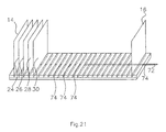
- Figure 21 a perspective view showing the electrode plate securing mechanism is provided. Anode electrode14, cathode electrode 16, and supplemental electrodes 24, 26, 28, 30 are held to rack 20 by holder rod 72 which slips through channels 74 in rack 20 and holes in the electrodes (not all the possible supplemental electrodes are illustrated in Figure 3 .)
- Rack 20 is preferably fabricated from a highly dielectric plastic such as PVC, polyethylene or polypropylene. Furthermore, rack 20 holds anode electrode 14, cathode electrode 16, and supplemental electrodes 24, 26, 28, 30 in a fixed spatial relationship.
- the fixed spatial relationship of the two principal electrodes and the one or more supplemental electrodes is such that the electrodes (two principal and one or more supplemental) are essentially parallel and each electrode is separated from an adjacent electrode by a distance from about 0.38 cm (0.15 inches) to about 0.89 cm (0.35 inches). More preferably, each electrode is separated from an adjacent electrode by a distance from about 4.2 to about 0.3 inches, and most preferably about 0.25 inches.
- the fixed spatial relationship is accomplished by a rack that holds the two principal electrodes and the one or more supplemental electrodes in the fixed spatial relationship.
- the electrodes sit in grooves in the rack which define the separations between each electrode.
- the electrodes are removable from the rack so that the electrodes or the rack may be changed if necessary.
- the supplemental electrodes are also held in place because they are secured to rack 20 by holder rod 72.
- Fig. 25 conceptually depicts an alternative arrangement where power is connected to a plurality of anodes 14 and cathodes 16 with the supplemental electrodes 24,26,28,30..., being neutral and not connected to a power source.
- the supplemental electrodes are located between anode electrode plates 14, between cathode electrode plates 16 or between cathode and anode electrode plates 14,16 as desired and the power is grounded to the electrolyzer chamber housing 4. In this configuration, equalized voltages are found to exist across the plates.
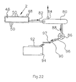
- Electrolyzer 2 is connected to collection tank 80 by pressure line 82. The gases are collected and temporarily stored in collection tank 80. Collection tank 80 optionally includes pressure relief valve 84 to guard against any dangerous pressure build up. Collection tank 80 is connected to solenoid 86 by pressure line 88. Solenoid 86 is in turn connected by pressure line 90 to engine intake manifold 92 of engine 94. Optionally, flash arrestor 96 is incorporated in pressure line 90 to prevent a flame from propagating in tube 88.
- pressure line 90 also includes orifice 97 to regulate the flow of the gaseous mixture into intake manifold 92.
- the size of this orifice will depend on the size of the engine. For example, an orifice diameter of about 0.04 is suitable for a 1 liter engine, about 0.06 inches is suitable for a 2.5 liter engine, and about 0.075 inches is suitable for a V8 engine.
- the applied voltage to electrolyzer 2 is provided through solenoid 98 by electrolyzer battery 100. When the pressure in collection tank 80 drops below about 25 psi, solenoid 98 switches and a voltage of about 12 V is applied between the anode electrode and cathode electrode of electrolyzer 2.
- Battery isolator 102 allows for charging of vehicle battery 104 and electrolyzer battery 100 by alternator 106 while keeping electrolyzer battery 100 and vehicle battery 104 electrically isolated. Furthermore, solenoid 98 is powered by vehicle battery 104 when main switch 108 is activated. Gas mixer solenoid 86 is also powered by vehicle battery 104 and opens when the gas mixture is provided to intake manifold 92. Solenoid 86 also receives feedback from level sensor 44 which causes solenoid 86 to shut off gas flow if the electrolyte solution level in electrolyzer 2 gets too low. Finally, when the method and apparatus of the present invention are used in a vehicle, the operation of the vehicle's oxygen sensor needs to be adjusted to take into account the additional oxygen that is added to the fuel system from the electrolyzer.
- Electrical lines 110, 112 of oxygen sensor 114 preferably include RC circuit 116.
- RC circuit 116 includes resistor 118 and capacitor 120.
- resistor 118 is about 1 megaohm and capacitor 120 is about 1 microfarad.
- Electrical line 110 is the check engine light signal and electrical line 112 carries the control signal that is related to the amount of oxygen in a vehicle exhaust. Resistor 118, which is in series in electrical line 110, ensures that the vehicle control system interprets the oxygen sensor as operating correctly.
- capacitor 120 provides the vehicle's computer with a signal such that the vehicles fuel injectors do not incorrectly open when the gas from electrolyzer 100 is being supplied to the fuel system.
- main switch 108 switches RC circuit in when gas is being supplied (i.e., the electrolyzer is being used) and out when gas is not being supplied.
- a method for increasing the fuel efficiency of an internal combustion engine utilizes the electrolyzer described above in conjunction with an internal combustion engine.
- the method comprises providing an electrolyzer equipment described above or as further described below in other novel embodiments; applying an electrical potential between the electrodes wherein the novel combustible gas described herein is generated and collected in the gas reservoir region and wherein the electrolyzer is adapted to deliver the combustible gas to the fuel system of an internal combustion engine; and combining the combustible gas produced with fuel in the fuel system of an internal combustion engine.
- the step of adjusting the operation of an oxygen sensor as set forth above is also provided.
- FIG. 24 is a flow diagram of another embodiment 300 of a gas (hydrogen and oxygen) electrolyzer generator system depicted in the figure as being used integrally with a welder/cutting torch type of equipment.
- This system can also be used in other types of equipment where heat/combustion is desired.
- This system 300 comprises an electrolyte reservoir 318, having a top and a bottom, containing electrolytic fluid 319 therein.
- the fluid herein is preferably water.
- the electrolyte reservoir 318 comprises a broken or permeable plate 320 which is sealably and circumferentially positioned around a top end of the electrolyte reservoir 318. Plate 320 functions to release gas pressure within the electrolyte reservoir 318 when exceeding a pre-determined safety level.
- the self-producing hydrogen and oxygen gas generating system 300 further comprises a pump 316, preferably an electromagnetic pump, which is connected at one distal end to the bottom of the electrolyte reservoir 318.
- Pump 316 is connected at an opposite distal end to at least one hydrogen and oxygen electrolyzer/generator 312 containing an electrical conductor 352 therein.
- the electrical conductor 352 is electrically connected on one distal end to an electrical ground.
- the opposite distal end of the electrical conductor 352 is electrically connected to one distal end of a pressure controller 328.
- the opposite distal end of the electrical conductor 352 is electrically connected to a power source.
- Pump 316 functions to circulate electrolytic fluid 319 from the electrolyte reservoir 318 through at least one hydrogen and oxygen electrolyzer/generator 312 through a radiator 314 back into the electrolyte reservoir 318 via a gas pipe 350.
- the radiator 314 functions to cool the generated hydrogen and oxygen gas before returning to the electrolyte reservoir 318.
- the pressure controller 328 is connected to the electrolyte reservoir 318 and monitors the pressure therein. When gas pressure within the electrolyte reservoir 318 exceeds a pre-determined level, electrical current is terminated to the electrical conductor 352 contained within the hydrogen and oxygen generator 312 thereby ceasing production of hydrogen and oxygen gas. When gas pressure within the electrolyte reservoir 318 drops below a pre-determined level, electrical current is connected to the electrical conductor 352 contained within the hydrogen and oxygen generator 312 thereby commencing production of hydrogen and oxygen gas.
- the preselected level is less than the preselected level required to cause a pressure release through plate 320.
- This self-producing on-demand hydrogen and oxygen generating system 300 further comprises a non-return valve 322 connected at one end to an upper end of the electrolyte reservoir 318 below plate 320.
- the non-return valve 322 is further connected to a dryer/filter means or tank 332 at an opposite distal end.
- System 300 further comprises another filter/dryer means or tank 330 in fluid communication with one end of the electrolyte reservoir 318 above plate 320 and further connected at an opposite distal end to another non-return valve 344 via gas line 342, which is connected at an opposite end to another filter/dryer means or tank 332.
- System 300 further comprises a decompression valve 326 in fluid communication at one end to the top end of the electrolyte reservoir 318 and further being in fluid communication with the gas pipe 350, which in turn is connected to radiator 314.
- the welding system 300 further comprises a microprocessor controlled D.C. amperage regulator 305 adapted to regulate the D.C. amperage from the power source to the hydrogen and oxygen generator 312.
- a first microprocessor controlled cut-off switch 306 is adapted to terminate the power source to the welder in response to a malfunction of the pump 316.
- a second microprocessor controlled cut-off switch 307 is adapted to terminate the power source to the welder in response to an insufficient electrolyte solution condition within the electrolyte reservoir 318.
- a microprocessor controlled liquid crystal display 308 is adapted to display operating statistics regarding the welding system 300, such statistics to include hours of operation, amperage, indicator lights and pressure gauge readings. The liquid crystal display receives input from a plurality of locations within the system 300.
- a microprocessor controlled polarity change system 309 is adapted to change the polarity of the electrical conductor located within the hydrogen and oxygen generator 312.
- a microprocessor controlled cool-down system 313 is adapted to operate a generator fan 311 and the pump 316 wherein operation of the fan and the pump continue throughout a cool-down stage following manual shut-off of the welder 300.
- the produced gas or HHO gas is routed from the dryer means 332 to the final gas reservoir tank 336.
- Dryer means 330 and 332 are only exemplary. It is understood that a single unit may be designed to effectively accomplish the same objective.
- the gas is then supplied on-demand to the engine or in this case, the welding equipment, through gas line 348 and hydrogen flash suppressor check valve (non-return valve) 338 and control valve 340.
- safety devices such as hydrogen flash suppressors and/or check valves may, when appropriate, be added components to any apparatus/systems.
Landscapes
- Chemical & Material Sciences (AREA)
- Organic Chemistry (AREA)
- Inorganic Chemistry (AREA)
- Engineering & Computer Science (AREA)
- Combustion & Propulsion (AREA)
- Electrolytic Production Of Non-Metals, Compounds, Apparatuses Therefor (AREA)
- Production Of Liquid Hydrocarbon Mixture For Refining Petroleum (AREA)
- Output Control And Ontrol Of Special Type Engine (AREA)
Applications Claiming Priority (1)
| Application Number | Priority Date | Filing Date | Title |
|---|---|---|---|
| US11/709,603 US20070151846A1 (en) | 2001-04-04 | 2007-02-22 | Apparatus and method for the conversion of water into a clean burning combustible gas for use as an additive with other forms of fuels |
Publications (2)
| Publication Number | Publication Date |
|---|---|
| EP1967614A2 true EP1967614A2 (fr) | 2008-09-10 |
| EP1967614A3 EP1967614A3 (fr) | 2009-01-14 |
Family
ID=39433809
Family Applications (1)
| Application Number | Title | Priority Date | Filing Date |
|---|---|---|---|
| EP07107267A Withdrawn EP1967614A3 (fr) | 2007-02-22 | 2007-04-30 | Appareil et procédé de conversion d'eau dans un gaz combustible propre à utiliser comme additif à d'autres sortes de combustibles |
Country Status (7)
| Country | Link |
|---|---|
| US (1) | US20070151846A1 (fr) |
| EP (1) | EP1967614A3 (fr) |
| CN (1) | CN101250709A (fr) |
| AU (1) | AU2007201275A1 (fr) |
| BR (1) | BRPI0701454A (fr) |
| CA (1) | CA2582698A1 (fr) |
| MX (1) | MX2007004873A (fr) |
Cited By (2)
| Publication number | Priority date | Publication date | Assignee | Title |
|---|---|---|---|---|
| DE202020100097U1 (de) | 2019-03-27 | 2020-03-19 | Franz Binzer | Gasgenerator zur Erzeugung von Wasserstoff-Sauerstoff-Mischgas und Vorrichtung zur Kraftstoffanreicherung für eine Verbrennungskraftmaschine |
| DE102019107872B4 (de) | 2019-03-27 | 2023-06-22 | Franz Binzer | Gasgenerator zur Erzeugung von Wasserstoff-Sauerstoff-Mischgas und Vorrichtung zur Kraftstoffanreicherung für eine Verbrennungskraftmaschine |
Families Citing this family (16)
| Publication number | Priority date | Publication date | Assignee | Title |
|---|---|---|---|---|
| WO2007033124A2 (fr) * | 2005-09-12 | 2007-03-22 | Mcmaster Fuel, Ltd. | Moteur a combustion interne presentant un electrolyseur embarque et procede d'utilisation |
| US7793621B2 (en) * | 2007-10-05 | 2010-09-14 | Realm Industries | Alternative fuel engine |
| GB2457500A (en) * | 2008-02-18 | 2009-08-19 | Robin Keith Nuttall | Solar powered brown's gas production unit |
| AU2009298157A1 (en) * | 2008-10-02 | 2010-04-08 | David Inwald | System and method for improving combustion using an electrolysis fuel cell |
| CN101445940B (zh) * | 2008-12-15 | 2011-05-04 | 李绅洋有限公司 | 一种产生氢氧助燃气体的节能装置及方法 |
| EP2554821A1 (fr) * | 2010-04-02 | 2013-02-06 | Masa International Corp. | Moteur thermique et système de production d'énergie au moyen du moteur thermique |
| US20140014049A1 (en) * | 2012-07-13 | 2014-01-16 | The Hydrogen Group, Inc. | System and method of improving fuel efficiency in vehicles using hho |
| EP2976446B1 (fr) * | 2013-03-19 | 2019-07-31 | Gilman, Brian, Daniel | Système d'alimentation portable en hydrogène et en oxygène |
| US9157159B2 (en) * | 2013-11-17 | 2015-10-13 | Don Lee Hansen | System and method for generating hydrogen and oxygen gases |
| CN104711626B (zh) * | 2013-12-13 | 2017-03-15 | 莫本 | 一种智能控制的节能减排装置及其方法 |
| US10386345B2 (en) * | 2015-03-19 | 2019-08-20 | Ford Global Technologies, Llc | Method and system for an oxygen sensor |
| US10180119B2 (en) | 2015-07-31 | 2019-01-15 | The Hydrogen Group, Inc. | System and method of improving fuel efficiency in vehicles using HHO |
| CN105297071A (zh) * | 2015-10-29 | 2016-02-03 | 鹤山市嘉德环保科技有限公司 | 一种高能气体 |
| CN105297070A (zh) * | 2015-10-29 | 2016-02-03 | 鹤山市嘉德环保科技有限公司 | 一种高能气体 |
| EP3196177A1 (fr) | 2016-01-21 | 2017-07-26 | HeidelbergCement AG | Hydrogene comme combustible dans la fabrication de ciment |
| WO2017165775A1 (fr) * | 2016-03-25 | 2017-09-28 | Carter International, Llc | Appareil à résonance électromagnétique pour modification moléculaire, atomique et chimique de l'eau |
Family Cites Families (29)
| Publication number | Priority date | Publication date | Assignee | Title |
|---|---|---|---|---|
| US3310483A (en) * | 1963-11-22 | 1967-03-21 | William A Rhodes | Multicell oxyhydrogen generator |
| US3627133A (en) * | 1970-03-16 | 1971-12-14 | Culligan Int Co | Chlorine generator for water softeners |
| US3893902A (en) * | 1973-04-12 | 1975-07-08 | Diamond Shamrock Corp | Electrolytic sea water process |
| US4081656A (en) * | 1973-07-20 | 1978-03-28 | Yull Brown | Arc-assisted oxy/hydrogen welding |
| US4014777A (en) * | 1973-07-20 | 1977-03-29 | Yull Brown | Welding |
| US4200062A (en) * | 1978-07-12 | 1980-04-29 | Duckworth Charles E | Safety switch for hydrogen generator system |
| US4181588A (en) * | 1979-01-04 | 1980-01-01 | The United States Of America As Represented By The Secretary Of The Interior | Method of recovering lead through the direct reduction of lead chloride by aqueous electrolysis |
| US4369737A (en) * | 1980-06-02 | 1983-01-25 | Sanders Cledith A | Hydrogen-oxygen generator |
| US4450060A (en) * | 1980-11-18 | 1984-05-22 | Ernesto Gonzalez | Bipolar electrolytic cell |
| US4622924A (en) * | 1983-06-20 | 1986-11-18 | Lewis William N | Hydrogen engine |
| US4726888A (en) * | 1986-12-04 | 1988-02-23 | Mccambridge Michael | Electrolysis of water |
| JP3278909B2 (ja) * | 1992-07-16 | 2002-04-30 | 株式会社豊田中央研究所 | 水素発生装置 |
| US5231954A (en) * | 1992-08-05 | 1993-08-03 | J. C. Conner | Hydrogen/oxygen fuel cell |
| US5244558A (en) * | 1992-09-24 | 1993-09-14 | Chiang Huang C | Apparatus for generating a mixture of hydrogen and oxygen for producing a hot flame |
| JPH08507828A (ja) * | 1993-03-15 | 1996-08-20 | ライディングズ ピーティーワイ リミテッド | 電解製造装置 |
| US5437250A (en) * | 1993-08-20 | 1995-08-01 | Massachusetts Institute Of Technology | Plasmatron-internal combustion engine system |
| WO1995007373A1 (fr) * | 1993-09-06 | 1995-03-16 | Hydrogen Technology Limited | Ameliorations relatives a des systemes d'electrolyse |
| US5813222A (en) * | 1994-10-07 | 1998-09-29 | Appleby; Anthony John | Method and apparatus for heating a catalytic converter to reduce emissions |
| US5628885A (en) * | 1995-11-13 | 1997-05-13 | Lin; Yang C. | Extraction installation for hydrogen and oxygen |
| US5614069A (en) * | 1996-06-12 | 1997-03-25 | Lin; I-Chuan | Apparatus for producing electrolytically and collecting separately two gases |
| US6689259B1 (en) * | 1998-01-30 | 2004-02-10 | Dennis Klein | Mixed gas generator |
| US6209493B1 (en) * | 1998-07-27 | 2001-04-03 | Global Tech Environmental Products Inc. | Internal combustion engine kit with electrolysis cell |
| US5997223A (en) * | 1998-09-22 | 1999-12-07 | Electro Scientific Industries, Inc. | High speed drilling spindle with reciprocating ceramic shaft and edoubl-gripping centrifugal chuck |
| US6560958B1 (en) * | 1998-10-29 | 2003-05-13 | Massachusetts Institute Of Technology | Emission abatement system |
| US6299656B1 (en) * | 1998-12-29 | 2001-10-09 | Charles A. McClure | Non-fossil fuel additives for predominantly hydrocarbon fuels |
| US6322757B1 (en) * | 1999-08-23 | 2001-11-27 | Massachusetts Institute Of Technology | Low power compact plasma fuel converter |
| US20040149591A1 (en) * | 2001-04-04 | 2004-08-05 | Dennis J. Klein | Apparatus and method for the conversion of water into a new gaseous and combustible form and the combustible gas formed thereby |
| US6866756B2 (en) * | 2002-10-22 | 2005-03-15 | Dennis Klein | Hydrogen generator for uses in a vehicle fuel system |
| WO2004027901A2 (fr) * | 2002-09-17 | 2004-04-01 | Diffusion Science, Inc. | Generation, stockage et reaction electrochimiques d'hydrogene et d'oxygene |
-
2007
- 2007-02-22 US US11/709,603 patent/US20070151846A1/en not_active Abandoned
- 2007-03-23 AU AU2007201275A patent/AU2007201275A1/en not_active Abandoned
- 2007-03-23 CA CA002582698A patent/CA2582698A1/fr not_active Abandoned
- 2007-04-18 BR BRPI0701454-6A patent/BRPI0701454A/pt not_active Application Discontinuation
- 2007-04-23 MX MX2007004873A patent/MX2007004873A/es unknown
- 2007-04-30 EP EP07107267A patent/EP1967614A3/fr not_active Withdrawn
- 2007-06-12 CN CNA2007101099546A patent/CN101250709A/zh active Pending
Cited By (2)
| Publication number | Priority date | Publication date | Assignee | Title |
|---|---|---|---|---|
| DE202020100097U1 (de) | 2019-03-27 | 2020-03-19 | Franz Binzer | Gasgenerator zur Erzeugung von Wasserstoff-Sauerstoff-Mischgas und Vorrichtung zur Kraftstoffanreicherung für eine Verbrennungskraftmaschine |
| DE102019107872B4 (de) | 2019-03-27 | 2023-06-22 | Franz Binzer | Gasgenerator zur Erzeugung von Wasserstoff-Sauerstoff-Mischgas und Vorrichtung zur Kraftstoffanreicherung für eine Verbrennungskraftmaschine |
Also Published As
| Publication number | Publication date |
|---|---|
| AU2007201275A1 (en) | 2008-09-11 |
| CN101250709A (zh) | 2008-08-27 |
| EP1967614A3 (fr) | 2009-01-14 |
| BRPI0701454A (pt) | 2008-10-07 |
| CA2582698A1 (fr) | 2008-08-22 |
| US20070151846A1 (en) | 2007-07-05 |
| MX2007004873A (es) | 2008-10-29 |
Similar Documents
| Publication | Publication Date | Title |
|---|---|---|
| EP1967614A2 (fr) | Appareil et procédé de conversion d'eau dans un gaz combustible propre à utiliser comme additif à d'autres sortes de combustibles | |
| US20040149591A1 (en) | Apparatus and method for the conversion of water into a new gaseous and combustible form and the combustible gas formed thereby | |
| US7191737B2 (en) | Hydrogen generator for uses in a vehicle fuel system | |
| Santilli | A new gaseous and combustible form of water | |
| JP2007519827A5 (fr) | ||
| US9284652B2 (en) | Electrolyzed hydrogen gas for fuel-fired boilers and hot water heaters | |
| JP2008274378A (ja) | 燃料の添加物として使用できるクリーンな可燃性ガスに水を変換する方法およびその装置 | |
| US20130175163A1 (en) | Apparatus and method for generating hydrogen from water | |
| US6673322B2 (en) | Apparatus for making a novel, highly efficient, nonpollutant, oxygen rich and cost competitive combustible gas and associated method | |
| US20090090312A1 (en) | Alternative Fuel Engine | |
| KR101698794B1 (ko) | 탄화수소의 생성 방법 | |
| US20230062648A1 (en) | Parahydrogen and atomic hydrogen fuel | |
| US20030113597A1 (en) | Apparatus and method to increase density and energy of hydrogen, oxygen, and other gases | |
| EP2610475A1 (fr) | Procédé et dispositif de modification de la composition moléculaire d'un carburant hydrocarbure liquide | |
| US20080038478A1 (en) | Thermal spray coating processes using HHO gas generated from an electrolyzer generator | |
| Sivakumar et al. | Generation of brown gas from a dry cell HHO generator using chemical decomposition reaction | |
| US9701917B2 (en) | System, method, and apparatus for the creation of parahydrogen and atomic hydrogen, and mixing of atomic hydrogen with a gas for fuel | |
| HK1117205A (en) | Apparatus and method for the conversion of water into a clean burning combustible gas for use as an additive with other forms of fuels | |
| CN105297070A (zh) | 一种高能气体 | |
| CN105297071A (zh) | 一种高能气体 | |
| Andriamampianina et al. | Optimal Conception of an Embarked Hydrogen Generator for Injection of an Auxiliary Additional Combustible into Gasoline Engines | |
| JP2014193807A (ja) | 水素発生方法及びその方法を実施する装置並びにその装置を用いた自動車用燃料発電装置 | |
| Sethuraman et al. | Submerged electric arc decomposition of methanol for cold-starting methanol-fueled engines | |
| BR202016010279U2 (pt) | Constructive arrangement applied in hydrogen generator |
Legal Events
| Date | Code | Title | Description |
|---|---|---|---|
| PUAI | Public reference made under article 153(3) epc to a published international application that has entered the european phase |
Free format text: ORIGINAL CODE: 0009012 |
|
| AK | Designated contracting states |
Kind code of ref document: A2 Designated state(s): AT BE BG CH CY CZ DE DK EE ES FI FR GB GR HU IE IS IT LI LT LU LV MC MT NL PL PT RO SE SI SK TR |
|
| AX | Request for extension of the european patent |
Extension state: AL BA HR MK RS |
|
| PUAL | Search report despatched |
Free format text: ORIGINAL CODE: 0009013 |
|
| AK | Designated contracting states |
Kind code of ref document: A3 Designated state(s): AT BE BG CH CY CZ DE DK EE ES FI FR GB GR HU IE IS IT LI LT LU LV MC MT NL PL PT RO SE SI SK TR |
|
| AX | Request for extension of the european patent |
Extension state: AL BA HR MK RS |
|
| AKX | Designation fees paid | ||
| REG | Reference to a national code |
Ref country code: DE Ref legal event code: 8566 |
|
| STAA | Information on the status of an ep patent application or granted ep patent |
Free format text: STATUS: THE APPLICATION IS DEEMED TO BE WITHDRAWN |
|
| 18D | Application deemed to be withdrawn |
Effective date: 20090715 |