EP1967720A2 - Procédé destiné au fonctionnement d'une pompe à carburant - Google Patents
Procédé destiné au fonctionnement d'une pompe à carburant Download PDFInfo
- Publication number
- EP1967720A2 EP1967720A2 EP07023288A EP07023288A EP1967720A2 EP 1967720 A2 EP1967720 A2 EP 1967720A2 EP 07023288 A EP07023288 A EP 07023288A EP 07023288 A EP07023288 A EP 07023288A EP 1967720 A2 EP1967720 A2 EP 1967720A2
- Authority
- EP
- European Patent Office
- Prior art keywords
- electric motor
- stator
- rotor
- fuel
- fuel pump
- Prior art date
- Legal status (The legal status is an assumption and is not a legal conclusion. Google has not performed a legal analysis and makes no representation as to the accuracy of the status listed.)
- Withdrawn
Links
Images
Classifications
-
- F—MECHANICAL ENGINEERING; LIGHTING; HEATING; WEAPONS; BLASTING
- F02—COMBUSTION ENGINES; HOT-GAS OR COMBUSTION-PRODUCT ENGINE PLANTS
- F02D—CONTROLLING COMBUSTION ENGINES
- F02D41/00—Electrical control of supply of combustible mixture or its constituents
- F02D41/02—Circuit arrangements for generating control signals
- F02D41/04—Introducing corrections for particular operating conditions
- F02D41/042—Introducing corrections for particular operating conditions for stopping the engine
-
- F—MECHANICAL ENGINEERING; LIGHTING; HEATING; WEAPONS; BLASTING
- F02—COMBUSTION ENGINES; HOT-GAS OR COMBUSTION-PRODUCT ENGINE PLANTS
- F02D—CONTROLLING COMBUSTION ENGINES
- F02D41/00—Electrical control of supply of combustible mixture or its constituents
- F02D41/30—Controlling fuel injection
- F02D41/3082—Control of electrical fuel pumps
-
- F—MECHANICAL ENGINEERING; LIGHTING; HEATING; WEAPONS; BLASTING
- F02—COMBUSTION ENGINES; HOT-GAS OR COMBUSTION-PRODUCT ENGINE PLANTS
- F02D—CONTROLLING COMBUSTION ENGINES
- F02D2200/00—Input parameters for engine control
- F02D2200/60—Input parameters for engine control said parameters being related to the driver demands or status
-
- F—MECHANICAL ENGINEERING; LIGHTING; HEATING; WEAPONS; BLASTING
- F02—COMBUSTION ENGINES; HOT-GAS OR COMBUSTION-PRODUCT ENGINE PLANTS
- F02D—CONTROLLING COMBUSTION ENGINES
- F02D41/00—Electrical control of supply of combustible mixture or its constituents
- F02D41/02—Circuit arrangements for generating control signals
- F02D41/04—Introducing corrections for particular operating conditions
- F02D41/06—Introducing corrections for particular operating conditions for engine starting or warming up
- F02D41/062—Introducing corrections for particular operating conditions for engine starting or warming up for starting
- F02D41/065—Introducing corrections for particular operating conditions for engine starting or warming up for starting at hot start or restart
Definitions
- the invention relates to a method for operating a fuel pump according to the preamble of claim 1 or 4.
- a fuel pump of a motor vehicle which serves to deliver fuel toward an internal combustion engine of the motor vehicle, has an EC electric motor to drive the fuel pump.
- a fuel pump is driven in such a way by the EC electric motor of the same that for the promotion of fuel in the direction of the internal combustion engine of the energized EC electric motor drives the fuel pump in a defined direction of rotation.
- the EC electric motor of the fuel pump is switched off to switch off the motor vehicle or its internal combustion engine.
- fuel pumps of the EC electric motor of the fuel pump is turned off such that a rotor of the EC electric motor due to its moment of inertia runs undefined and stops in any relative position to the stator of the EC electric motor.
- a subsequent starting of the internal combustion engine must then be carried out in advance synchronization between the rotor and the stator of the EC electric motor, so that a certain time elapses until a required for the start of the engine to be performed first ignition amount of fuel and a required fuel pressure are provided can.
- the time required to synchronize the rotor and stator of the EC electric motor is considered disadvantageous.
- the present invention based on the problem to provide a novel method for operating a fuel pump.
- this problem is solved by a method according to claim 1. After that, when no more fuel is needed, the EC electric motor of the fuel pump is turned off such that a rotor of the EC electric motor expires defined, so that after the run of the EC electric motor assumes a defined relative position to the stator of the EC electric motor ,
- this problem is solved by a method according to claim 4. Thereafter, when no more fuel is needed, the EC electric motor of the fuel pump is turned off such that a rotor of the EC electric motor runs undefined, then at least one pair of coils of the stator of the EC electric motor is energized so that the rotor of the EC -Electric motor occupies a defined relative position to the stator of the EC electric motor.
- Both aspects of the present invention have in common that for the first ignition when starting an internal combustion engine, the required amount of fuel and the required fuel pressure can be provided within a very short time.
- the EC electric motor of the fuel pump is turned off such that the rotor of the same expires defined, so that the same assumes a defined relative position to the stator of the EC electric motor after running out.
- the rotor of the EC electric motor runs undefined, after the leakage, however, at least one pair of coils of the stator of the EC electric motor is energized so that the rotor of the EC electric motor thereof transferred to the defined relative position to the stator becomes.
- the necessary amount of fuel and the required fuel pressure can be provided within a very short time for the first ignition.
- the present invention relates to a method for operating a fuel pump of a motor vehicle.
- a fuel pump is driven by an electric motor.
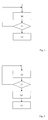
- the operation of the fuel pump via the electric motor for conveying fuel toward an internal combustion engine is in Fig. 1 visualized by a block 10.
- the fuel pump is driven by an EC electric motor.
- a subsequent block 11 it is checked whether fuel is still needed. Then, when it is determined in the subsequent block 11 that fuel is no longer needed, the system branches to block 12 and the EC electric motor of the fuel pump is turned off in block 12. If, on the other hand, it is determined in block 11 that fuel is still needed, branching back to block 10 takes place.
- the rotating magnetic field of the stator is changed such that a speed of the rotor is preferably continuously reduced, and the rotor stops in the defined relative position to the stator of the EC electric motor.
- This change in the magnetic field of the stator takes over the control unit of the EC electric motor.
- the rotating magnetic field of the stator of the EC electric motor is stopped in a defined angular position, so that the rotor of the EC electric motor stops in the defined relative position to the stand.
- the inventive method according to the first aspect of the present invention finds particular use when the fuel pump is operated by an EC electric motor with integrated position sensor.
- the EC electric motor of the fuel pump in block 13 is turned off such that the rotor first runs undefined, wherein then in block 14 at least one coil pair of the stator is energized such that the rotor is transferred to a defined relative position to the stator of the EC electric motor and occupies this relative position. If, on the other hand, it is determined in block 11 that fuel is still needed, then in accordance with the signal flow diagram of FIG Fig. 1 back to block 10 and the fuel pump continues to be driven by the EC electric motor.
- the transfer of the rotor into a defined relative position to the stator of the EC electric motor according to block 14 can take place either immediately following the undefined running out of the rotor or immediately before a subsequently to be executed engine start.
- the corresponding current supply of the electric motor is preferably triggered by unlocking a motor vehicle locking system.
- the fuel pump namely the EC electric motor of the same operate in a low speed range, so as to fill the fuel system of the motor vehicle and build up a defined fuel pressure before the actual start of the engine.
- This can cause noise the fuel pump can be reduced when the internal combustion engine is not running.
- the fuel pressure required for the first ignition and the required amount of fuel can be provided even faster.
- the position of the fuel pump namely the relative position between the stator and the rotor of the EC electric motor of the fuel pump, is known, so that no synchronization between stator and rotor must be performed.
- the starting time of the internal combustion engine can be reduced because the fuel pressure required for the first ignition and the required fuel quantity can be provided within a very short time.
Landscapes
- Engineering & Computer Science (AREA)
- Chemical & Material Sciences (AREA)
- Combustion & Propulsion (AREA)
- Mechanical Engineering (AREA)
- General Engineering & Computer Science (AREA)
- Hybrid Electric Vehicles (AREA)
- Control Of Motors That Do Not Use Commutators (AREA)
- Structures Of Non-Positive Displacement Pumps (AREA)
Applications Claiming Priority (1)
| Application Number | Priority Date | Filing Date | Title |
|---|---|---|---|
| DE102007011018A DE102007011018A1 (de) | 2007-03-07 | 2007-03-07 | Verfahren zum Betreiben einer Kraftstoffpumpe |
Publications (2)
| Publication Number | Publication Date |
|---|---|
| EP1967720A2 true EP1967720A2 (fr) | 2008-09-10 |
| EP1967720A3 EP1967720A3 (fr) | 2013-09-25 |
Family
ID=39536476
Family Applications (1)
| Application Number | Title | Priority Date | Filing Date |
|---|---|---|---|
| EP07023288.9A Withdrawn EP1967720A3 (fr) | 2007-03-07 | 2007-11-30 | Procédé destiné au fonctionnement d'une pompe à carburant |
Country Status (4)
| Country | Link |
|---|---|
| US (1) | US20080218105A1 (fr) |
| EP (1) | EP1967720A3 (fr) |
| JP (1) | JP2008220163A (fr) |
| DE (1) | DE102007011018A1 (fr) |
Cited By (2)
| Publication number | Priority date | Publication date | Assignee | Title |
|---|---|---|---|---|
| EP2884076A3 (fr) * | 2013-10-14 | 2015-12-02 | Continental Automotive GmbH | Dispositif et procédé de commande d'une pompe diesel en cas de pression de refoulement nulle |
| CN108071509A (zh) * | 2016-11-16 | 2018-05-25 | 福特环球技术公司 | 用于操作提升泵的系统和方法 |
Families Citing this family (10)
| Publication number | Priority date | Publication date | Assignee | Title |
|---|---|---|---|---|
| US7712445B2 (en) * | 2006-11-09 | 2010-05-11 | Gm Global Technology Operations, Inc. | Fuel pressure boost method and apparatus |
| US8151767B2 (en) * | 2007-08-08 | 2012-04-10 | Ford Global Technologies, Llc | Fuel control for direct injection fuel system |
| US7640916B2 (en) * | 2008-01-29 | 2010-01-05 | Ford Global Technologies, Llc | Lift pump system for a direct injection fuel system |
| SE535632C2 (sv) | 2010-06-21 | 2012-10-23 | Scania Cv Ab | Förfarande vid förekomst av luft i vätsketillförsel vid ett SCR-system och motsvarande SCR-system |
| SE536920C2 (sv) | 2010-06-21 | 2014-10-28 | Scania Cv Ab | SCR-system för avgasrening och förfarande för kylning av endoseringsenhet vid ett sådant SCR-system |
| SE536873C2 (sv) * | 2010-06-21 | 2014-10-14 | Scania Cv Ab | HC-doseringssystem för avgasrening samt förfarande för kylning därav |
| US8635854B2 (en) * | 2011-08-05 | 2014-01-28 | Tenneco Automotive Operating Company Inc. | Reductant injection control system |
| CN102588170B (zh) * | 2012-03-13 | 2014-07-16 | 潍柴动力股份有限公司 | 一种电动燃油泵控制方法及系统 |
| JP2013236431A (ja) * | 2012-05-08 | 2013-11-21 | Mitsubishi Electric Corp | ブラシレスモータの制御方法及び制御装置 |
| FR3013395B1 (fr) * | 2013-11-19 | 2015-12-11 | Renault Sas | Procede et systeme d'alimentation en gazole d'un vehicule automobile. |
Family Cites Families (15)
| Publication number | Priority date | Publication date | Assignee | Title |
|---|---|---|---|---|
| US3715643A (en) * | 1970-03-31 | 1973-02-06 | Yamato Sewing Machine Mfg | Electrically driven motor |
| US5120201A (en) * | 1990-12-17 | 1992-06-09 | Walbro Corporation | Brushless DC fuel pump responsive to pressure sensor |
| JPH04275093A (ja) * | 1991-02-28 | 1992-09-30 | Sony Corp | ブラシレスモータ駆動回路 |
| JPH07226016A (ja) * | 1994-02-14 | 1995-08-22 | Fujitsu Ltd | ディスク装置のモータ起動制御方法 |
| JPH0870593A (ja) * | 1994-08-29 | 1996-03-12 | Namiki Precision Jewel Co Ltd | 3相ブラシレスモータの制御装置 |
| JPH08266088A (ja) * | 1995-03-27 | 1996-10-11 | Nippondenso Co Ltd | 電動機用制御装置 |
| JP2000060070A (ja) * | 1998-08-06 | 2000-02-25 | Denso Corp | ブラシレスモータ |
| US6104153A (en) * | 1999-02-23 | 2000-08-15 | Western Digital Corporation | Disk drive employing method of spinning down its spindle motor to reduce the time required for spinning it down and subsequently spinning it up |
| DE19955247A1 (de) * | 1999-11-17 | 2001-05-31 | Bosch Gmbh Robert | Verfahren zum Anfahren eines sensor- und bürstenlosen Gleichstrommotors |
| DE19961298A1 (de) * | 1999-12-18 | 2001-06-21 | Bosch Gmbh Robert | Verfahren zur Ansteuerung einer Kraftstoffpumpe |
| JP2004364473A (ja) * | 2003-06-09 | 2004-12-24 | Nippon Densan Corp | モータ起動方法及びモータ起動装置 |
| CN100507257C (zh) * | 2003-09-18 | 2009-07-01 | A.凯塞汽车系统有限公司 | 用于燃料供给系统的阀及过滤装置 |
| US7514887B2 (en) * | 2003-10-24 | 2009-04-07 | A. O. Smith Corporation | Electrical machine and method of controlling the same |
| JP2006299947A (ja) * | 2005-04-21 | 2006-11-02 | Nissan Motor Co Ltd | エンジンの燃料供給装置 |
| KR100725174B1 (ko) * | 2005-10-10 | 2007-06-04 | 삼성전기주식회사 | 브러시리스 직류모터의 제어장치 및 제어방법 |
-
2007
- 2007-03-07 DE DE102007011018A patent/DE102007011018A1/de not_active Withdrawn
- 2007-11-30 EP EP07023288.9A patent/EP1967720A3/fr not_active Withdrawn
-
2008
- 2008-03-06 JP JP2008055667A patent/JP2008220163A/ja active Pending
- 2008-03-07 US US12/044,105 patent/US20080218105A1/en not_active Abandoned
Cited By (3)
| Publication number | Priority date | Publication date | Assignee | Title |
|---|---|---|---|---|
| EP2884076A3 (fr) * | 2013-10-14 | 2015-12-02 | Continental Automotive GmbH | Dispositif et procédé de commande d'une pompe diesel en cas de pression de refoulement nulle |
| CN108071509A (zh) * | 2016-11-16 | 2018-05-25 | 福特环球技术公司 | 用于操作提升泵的系统和方法 |
| CN108071509B (zh) * | 2016-11-16 | 2022-06-03 | 福特环球技术公司 | 用于操作提升泵的系统和方法 |
Also Published As
| Publication number | Publication date |
|---|---|
| JP2008220163A (ja) | 2008-09-18 |
| US20080218105A1 (en) | 2008-09-11 |
| EP1967720A3 (fr) | 2013-09-25 |
| DE102007011018A1 (de) | 2008-09-11 |
Similar Documents
| Publication | Publication Date | Title |
|---|---|---|
| DE102007011018A1 (de) | Verfahren zum Betreiben einer Kraftstoffpumpe | |
| EP2010759B1 (fr) | Dispositif de synchronisation pour un moteur | |
| DE10362105B4 (de) | Motorsteuerungsgerät | |
| DE4430651B4 (de) | Verfahren zum Anlassen eines Fahrzeug-Verbrennungsmotors | |
| DE10330809B4 (de) | Motorsteuerungsgerät | |
| DE10030001A1 (de) | Vorrichtung und Verfahren zum kontrollierten Abstellen einer Brennkraftmaschine | |
| EP1586765A1 (fr) | Procédé et système de commande pour positioner les vilebrequine lors de l'arrêt d'un moteur à combustion | |
| DE102004037584B4 (de) | Verfahren zum Betreiben einer Antriebseinheit | |
| DE10062985A1 (de) | Verfahren und Steuereinrichtung zum Bestimmen des Kurbelwellenwinkels von einer Brennkraftmaschine sowie Antriebsstrang | |
| DE102015219335B3 (de) | Verfahren zum Steuern eines Verbrennungsmotors mit einer Nockenwelle | |
| DE112007000702T5 (de) | Bürstenlose Motorvorrichtung | |
| WO1999054620A1 (fr) | Unite de demarrage et d'entrainement pour moteur a combustion interne d'un vehicule | |
| DE112009002235B4 (de) | Verfahren und Vorrichtung zur Steuerung der Position eines Elektromotors | |
| DE102006035385B4 (de) | Anormalzustand-Erfassungssystem für eine Maschine | |
| DE112014000754T5 (de) | Starter- und Schaltsystem mit variablem Fluss | |
| WO2005047659A1 (fr) | Systeme d'ajustement d'arbre a cames muni d'une commande electrique | |
| DE102021212310A1 (de) | Verfahren zum Betreiben eines einsträngigen Elektromotors | |
| WO2006102981A1 (fr) | Moteur submersible | |
| DE102012219297A1 (de) | Verfahren zum Betreiben eines Kraftfahrzeugs | |
| DE102004003153A1 (de) | Steuervorrichtung und Steuerverfahren für einen Elektromotor | |
| DE10254735A1 (de) | Brennkraftmaschine, sowie Verfahren zum Betreiben einer Brennkraftmaschine | |
| EP1967725A2 (fr) | Procédé destiné au fonctionnement d'une pompe à carburant | |
| EP1870999B1 (fr) | Procédé de fonctionnement d'une pompe dotée d'une machine électrique à commutation électronique | |
| EP1873898A2 (fr) | Procédé destiné à la régulation d'une pompe destinée à l'approvisionnement d'un milieu liquide | |
| EP1541843A1 (fr) | Procédé et dispositif de commande pour déterminer l'arrêt d'un moteur à combustion |
Legal Events
| Date | Code | Title | Description |
|---|---|---|---|
| PUAI | Public reference made under article 153(3) epc to a published international application that has entered the european phase |
Free format text: ORIGINAL CODE: 0009012 |
|
| AK | Designated contracting states |
Kind code of ref document: A2 Designated state(s): AT BE BG CH CY CZ DE DK EE ES FI FR GB GR HU IE IS IT LI LT LU LV MC MT NL PL PT RO SE SI SK TR |
|
| AX | Request for extension of the european patent |
Extension state: AL BA HR MK RS |
|
| RAP1 | Party data changed (applicant data changed or rights of an application transferred) |
Owner name: DR. ING. H.C. F. PORSCHE AG |
|
| PUAL | Search report despatched |
Free format text: ORIGINAL CODE: 0009013 |
|
| RIC1 | Information provided on ipc code assigned before grant |
Ipc: F02D 41/30 20060101ALI20130814BHEP Ipc: F02D 33/00 20060101ALI20130814BHEP Ipc: F02D 41/04 20060101AFI20130814BHEP Ipc: F02D 41/06 20060101ALN20130814BHEP |
|
| AK | Designated contracting states |
Kind code of ref document: A3 Designated state(s): AT BE BG CH CY CZ DE DK EE ES FI FR GB GR HU IE IS IT LI LT LU LV MC MT NL PL PT RO SE SI SK TR |
|
| AX | Request for extension of the european patent |
Extension state: AL BA HR MK RS |
|
| REG | Reference to a national code |
Ref country code: DE Ref legal event code: R108 |
|
| AKY | No designation fees paid | ||
| REG | Reference to a national code |
Ref country code: DE Ref legal event code: R108 Effective date: 20140527 |
|
| STAA | Information on the status of an ep patent application or granted ep patent |
Free format text: STATUS: THE APPLICATION IS DEEMED TO BE WITHDRAWN |
|
| 18D | Application deemed to be withdrawn |
Effective date: 20140326 |