EP1967728B1 - Kupplungsvorrichtung und Kraftstoffzufuhranordnung - Google Patents
Kupplungsvorrichtung und Kraftstoffzufuhranordnung Download PDFInfo
- Publication number
- EP1967728B1 EP1967728B1 EP07004823A EP07004823A EP1967728B1 EP 1967728 B1 EP1967728 B1 EP 1967728B1 EP 07004823 A EP07004823 A EP 07004823A EP 07004823 A EP07004823 A EP 07004823A EP 1967728 B1 EP1967728 B1 EP 1967728B1
- Authority
- EP
- European Patent Office
- Prior art keywords
- fuel
- fuel injector
- coupling device
- injector cup
- tube
- Prior art date
- Legal status (The legal status is an assumption and is not a legal conclusion. Google has not performed a legal analysis and makes no representation as to the accuracy of the status listed.)
- Not-in-force
Links
Images


Classifications
-
- F—MECHANICAL ENGINEERING; LIGHTING; HEATING; WEAPONS; BLASTING
- F02—COMBUSTION ENGINES; HOT-GAS OR COMBUSTION-PRODUCT ENGINE PLANTS
- F02M—SUPPLYING COMBUSTION ENGINES IN GENERAL WITH COMBUSTIBLE MIXTURES OR CONSTITUENTS THEREOF
- F02M55/00—Fuel-injection apparatus characterised by their fuel conduits or their venting means; Arrangements of conduits between fuel tank and pump F02M37/00
- F02M55/02—Conduits between injection pumps and injectors, e.g. conduits between pump and common-rail or conduits between common-rail and injectors
-
- F—MECHANICAL ENGINEERING; LIGHTING; HEATING; WEAPONS; BLASTING
- F02—COMBUSTION ENGINES; HOT-GAS OR COMBUSTION-PRODUCT ENGINE PLANTS
- F02M—SUPPLYING COMBUSTION ENGINES IN GENERAL WITH COMBUSTIBLE MIXTURES OR CONSTITUENTS THEREOF
- F02M55/00—Fuel-injection apparatus characterised by their fuel conduits or their venting means; Arrangements of conduits between fuel tank and pump F02M37/00
- F02M55/004—Joints; Sealings
- F02M55/005—Joints; Sealings for high pressure conduits, e.g. connected to pump outlet or to injector inlet
-
- F—MECHANICAL ENGINEERING; LIGHTING; HEATING; WEAPONS; BLASTING
- F02—COMBUSTION ENGINES; HOT-GAS OR COMBUSTION-PRODUCT ENGINE PLANTS
- F02M—SUPPLYING COMBUSTION ENGINES IN GENERAL WITH COMBUSTIBLE MIXTURES OR CONSTITUENTS THEREOF
- F02M2200/00—Details of fuel-injection apparatus, not otherwise provided for
- F02M2200/80—Fuel injection apparatus manufacture, repair or assembly
- F02M2200/803—Fuel injection apparatus manufacture, repair or assembly using clamp elements and fastening means; e.g. bolts or screws
-
- F—MECHANICAL ENGINEERING; LIGHTING; HEATING; WEAPONS; BLASTING
- F02—COMBUSTION ENGINES; HOT-GAS OR COMBUSTION-PRODUCT ENGINE PLANTS
- F02M—SUPPLYING COMBUSTION ENGINES IN GENERAL WITH COMBUSTIBLE MIXTURES OR CONSTITUENTS THEREOF
- F02M2200/00—Details of fuel-injection apparatus, not otherwise provided for
- F02M2200/80—Fuel injection apparatus manufacture, repair or assembly
- F02M2200/8084—Fuel injection apparatus manufacture, repair or assembly involving welding or soldering
-
- F—MECHANICAL ENGINEERING; LIGHTING; HEATING; WEAPONS; BLASTING
- F02—COMBUSTION ENGINES; HOT-GAS OR COMBUSTION-PRODUCT ENGINE PLANTS
- F02M—SUPPLYING COMBUSTION ENGINES IN GENERAL WITH COMBUSTIBLE MIXTURES OR CONSTITUENTS THEREOF
- F02M2200/00—Details of fuel-injection apparatus, not otherwise provided for
- F02M2200/85—Mounting of fuel injection apparatus
- F02M2200/855—Mounting of fuel injection apparatus using clamp elements or fastening means, e.g. bolts or screws
-
- F—MECHANICAL ENGINEERING; LIGHTING; HEATING; WEAPONS; BLASTING
- F02—COMBUSTION ENGINES; HOT-GAS OR COMBUSTION-PRODUCT ENGINE PLANTS
- F02M—SUPPLYING COMBUSTION ENGINES IN GENERAL WITH COMBUSTIBLE MIXTURES OR CONSTITUENTS THEREOF
- F02M2200/00—Details of fuel-injection apparatus, not otherwise provided for
- F02M2200/85—Mounting of fuel injection apparatus
- F02M2200/856—Mounting of fuel injection apparatus characterised by mounting injector to fuel or common rail, or vice versa
Definitions
- the invention relates to a coupling device for coupling a fuel injector to a fuel rail of a combustion engine and a fuel supply arrangement.
- Fuel injectors are in wide spread use, in particular for internal combustion engines where they may be arranged in order to dose fuel into an intake manifold of the internal combustion engine or directly into the combustion chamber of a cylinder of the internal combustion engine. Fuel can be supplied to the internal combustion engine by the fuel injector.
- a fuel accumulator to which the fuel injectors are connected and which has a relatively large volume.
- a fuel accumulator is often referred to as a fuel rail.
- the fuel injectors can be coupled to the fuel rail of the internal combustion engine in different manners.
- Known fuel rails comprise a hollow body with recesses in form of fuel injector cups, wherein the fuel injectors are arranged.
- the connection of the fuel injectors to the fuel injector cups that supply the fuel from a fuel tank via a low or high-pressure fuel pump needs to be very precise to get a correct injection quantity and to provide an adequate sealing and orientation.
- US 5,394,850 discloses a top-feed fuel injector.
- a rigid connector tube telescopically engages the fuel rail and the inlet of a top-feed fuel injector.
- Various embodiments of such connector tubes are disclosed.
- Such connector tubes enable a top-feed fuel injector to be used in an integrated air-fuel system where a fuel rail is integrally formed with a manifold such that the fuel supply ports of the fuel rail are in fixed spatial relation to the fuel injection ports of the manifold.
- EP 1 752 655 A1 discloses a device that comprises a connection tube in communication with a hole of a rail for fuel under pressure, the tube being provided with an end swelling.
- the device comprises a first threaded element fixed to the rail in a position corresponding to the hole and a second threaded element designed to engage the first threaded element.
- Removably set between the hole and the swelling is a seal element designed to form a seal both with the hole and with the swelling.
- the seal element is a body of revolution equipped with a passage along a pre-set axis, and comprises two end noses designed to be inserted in the swelling and in the hole, respectively, and two tapered seal stretches.
- US 2004/0118382 discloses a fuel rail assembly for supplying fuel to a plurality of fuel injectors in an engine.
- This assembly comprises an elongated conduit having a longitudinal fuel passage therein, a fuel inlet pipe fixed to an end or a side of the conduit, and a plurality of branch pipes.
- the former end of each branch pipe is adapted to communicate with the fuel passage.
- the rear end of each branch pipe is provide with a connecting member for receiving a tip of a fuel injector.
- the wall of the conduit is provided with holes for receiving the former ends of the branch pipes.
- Each branch pipe is fixed to collars around the holes by brazing or welding.
- the object is to create a coupling device which is simply to be manufactured and which facilitates a reliable and precise connection between the fuel injector and the fuel injector cup.
- the invention is distinguished by a coupling device for hydraulically coupling a fuel injector to a fuel rail of a combustion engine comprising a fuel injector cup being designed to engage a fuel inlet portion of the fuel injector, and a tube with a first end and a second end, the first end being coupable to the fuel rail and the second end being coupled to the fuel injector cup.
- the fuel injector cup comprises a protrusion, the protrusion being designed to enable a rigid coupling of the fuel injector cup to a cylinder head of the combustion engine.
- the protrusion enables that the fuel injector cup is rigidly coupable to the cylinder head by simple means. Additionally, the fuel injector can be fixed in the cylinder head in a secure manner.
- the tube is rigid.
- a coupling nut is coupled to the first end of the tube and is designed to sealingly interact with the fuel rail.
- the first end of the tube is brazed or welded to the fuel rail.
- the fuel injector cup is brazed or welded to the second end of the tube.
- the fuel injector cup comprises a plurality of protrusions circumferentially distributed relative to a central longitudinal axis of the fuel injector cup and extends in radial direction relative to the central longitudinal axis of the fuel injector cup. This makes it possible to rigidly couple the fuel injector cup to the cylinder head by a robust mean.
- the protrusions comprise orifices being designed to engage fixing elements, the fixing elements being designed to rigidly couple the fuel injector cup to the cylinder head of the combustion engine. This enables a rigid coupling of the fuel injector cup to the cylinder head by robust means.
- the fixing elements are screws engaging the cylinder head of the combustion engine. This gives the possibility to couple the fuel injector cup rigidly to the cylinder head by robust means.
- the invention is distinguished by a fuel supply arrangement comprising a coupling device according to the first aspect and a fuel rail being hydraulically coupled to the coupling device.
- a fuel feed device 10 is assigned to an internal combustion engine 22 ( figure 1 ). It includes a fuel tank 12 that is connected via a first fuel line to a fuel pump 14. The output of the fuel pump 14 is connected to a fuel inlet 16 of a fuel rail 18. Fuel injectors 20 are connected to the fuel rail 18. The fuel is fed to the fuel injectors 20 via the fuel rail 18. The fuel injectors 20 have a sealed connection to the fuel rail 18.
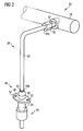
- a fuel supply arrangement 60 comprises the fuel rail 18 and a coupling device 30.
- the coupling device 30 has a tube 32 and a fuel injector cup 38 and is arranged between the fuel rail 18 and the fuel injector 20 to hydraulically couple the fuel injector 20 to the fuel rail 18 ( figure 2 ).
- the fuel injector 20 is suitable for injecting fuel into a gasoline engine.
- the tube 32 of the coupling device 30 has a first end 34a and a second end 34b.
- the first end 34a of the tube 32 is coupled to the fuel rail 18 by a metal to metal connection comprising a coupling nut 36 with an inner thread and a bolt 37 with an outer thread.
- the bolt 37 is rigidly coupled to the fuel rail 18 and the coupling nut 36 is coupled to the bolt 37 by a screw connection.
- the fuel injector cup 38 is coupled to the second end 34b of the tube 32 by a weld seam 42.
- Figure 3 shows the coupling device 30 and the fuel injector 20 in detail.
- the fuel injector 20 has a fuel injector body 24 with a fuel inlet portion 26, a not shown fuel outlet portion and an outer surface 28.
- the fuel injector cup 38 is cup-shaped with a central longitudinal axis L and is designed to receive the fuel injector body 24 of the fuel injector 20.
- an inner surface 40 of the fuel injector cup 38 is designed as a smooth wall.
- a sealing ring 46 is arranged between the fuel injector body 24 and the fuel injector cup 38 to obtain a good sealing between the fuel injector 20 and the fuel injector cup 38.
- the coupling device 30 can be coupled to the fuel injector 20 by coupling arrangements different from the sealing ring 46 between the fuel injector cup 38 and the fuel injector 20.
- the inner surface 40 of the fuel injector cup 38 comprises a thread which is in engagement with a thread on the outer surface 28 of the fuel injector body 24 of the fuel injector 20.
- the fuel injector cup 38 has two protrusions 48 which extend in radial direction relative to the central longitudinal axis L of the fuel injector cup 38.
- Each of the protrusions 48 has an orifice 52 which is designed to take in a fixing element 50.
- the fixing element 50 is designed to rigidly couple the fuel injector cup 38 to a cylinder head 54 of the combustion engine 22.
- the fixing element 50 is preferably a screw but it may also be of another sort as a pin or a bolt as long as it enables a fixed coupling of the fuel injector cup 38 to the cylinder head 54.
- the number of protrusions 48 can be different from two as long as the protrusions 48 allow a rigid coupling of the fuel injector cup 38 to the cylinder head 54 of the combustion engine 22. It is preferred that the protrusions 48 are circumferentially distributed relative to the central longitudinal axis L of the fuel injector cup 38. By this a well-balanced distribution of the mechanical forces between the fuel injector cup 38 and the cylinder head 54 can be obtained.
- a distance element 58 is arranged to enable a defined distance between the fuel injector cup 38 and the cylinder head 54 of the combustion engine 22. Additionally, the distance element 58 is designed to receive the fixing element 50.
- a spring 56 is arranged to apply an axial force on the injector 20 to balance pressure changes in the cylinder head 54 of the combustion engine 22.
- the spring 56 may also comprise an orientation means which enables an exact alignment of the fuel injector 20 relative to the fuel injector cup 38.
- the orientation means is preferably a tab or a recess which interacts with a respective recess or tab which is preferably at the fuel injector 20 or at the fuel injector cup 38.
- additional centering or positioning elements are arranged between the cylinder head 54 and the fuel injector cup 38 if a particular orientation of the fuel injector 20 or a particular positioning of the fuel injector cup 38 is necessary.
- the fuel injector cup 38 and the tube 42 are preferably made out of stainless steel. This enables to reduce the corrosion of the coupling device 30.
- the coupling device 30 can overcome the distance between the fuel injector 20 and the fuel rail 18.
- the tube 32 of the coupling device 30 has a length and a design enabling to overcome the distance between the fuel injector 20 and the fuel rail 18.
- the coupling device 30 is coupled to the fuel rail 18 by the metal-metal connection carried out by the coupling nut 36 and the bolt 37.
- the first end 34a of the tube 32 is brazed or welded directly to the fuel rail 18.
- the fuel injector cup 38 is brazed or welded to the second end 30b of the tube 32.
- a secure rigid coupling of the fuel injector 38 and tube 32 is obtainable.
- the tube 32 can be bended in a way that the fuel injector cup 38 can be coupled to the fuel injector 20 dependent on the position and orientation of the fuel injector 20 relative to the fuel rail 18 a high flexibility of the coupling of the fuel injector 20 to the fuel rail 18 is obtainable by the coupling device 30 comprising the tube 32.
Landscapes
- Engineering & Computer Science (AREA)
- Chemical & Material Sciences (AREA)
- Combustion & Propulsion (AREA)
- Mechanical Engineering (AREA)
- General Engineering & Computer Science (AREA)
- Fuel-Injection Apparatus (AREA)
Claims (9)
- Kupplungsvorrichtung (30) zum hydraulischen Kuppeln eines Kraftstoff-Injektors (20) an ein Kraftstoff-Verteilerrohr (18) eines Verbrennungsmotors (22), umfassend- ein Kraftstoff-Injektor-Becher (38), der ausgelegt ist, um mit einem Kraftstoff-Einlassabschnitt (26) des Kraftstoff-Injektors (20) in Eingriff zu stehen und- ein Rohr (32) mit einem ersten Ende (34a) und einem zweiten Ende (34b), wobei das erste Ende (34a) an das Kraftstoff-Verteilerrohr (18) und das zweite Ende (34b) an den Kraftstoff-Injektor-Becher (38) gekuppelt werden kann,dadurch gekennzeichnet, dass
der Kraftstoff-Injektor-Becher (38) einen Vorsprung (48) umfasst, wobei der Vorsprung (48) ausgelegt ist, um ein starres Kuppeln des Kraftstoff-Injektor-Bechers (38) an einen Zylinderkopf (54) des Verbrennungsmotors (22) zu ermöglichen. - Kupplungsvorrichtung (30) nach Anspruch 1, wobei das Rohr (32) starr ist.
- Kupplungsvorrichtung (30) nach Anspruch 1 oder 2, wobei eine Kupplungsmutter (36) an das erste Ende (34a) des Rohrs (32) gekuppelt wird und ausgelegt ist, um dichtend mit dem Kraftstoff-Verteilerrohr (18) in Wechselwirkung zu treten.
- Kupplungsvorrichtung (30) nach Anspruch 1 oder 2, wobei das erste Ende (34a) des Rohrs (32) an das Kraftstoff-Verteilerrohr (18) gelötet oder geschweißt ist.
- Kupplungsvorrichtung (30) nach einem der vorhergehenden Ansprüche, wobei der Kraftstoff-Injektor-Becher (38) an das zweite Ende (34b) des Rohrs (32) gelötet oder geschweißt ist.
- Kupplungsvorrichtung (30) nach einem der vorhergehenden Ansprüche, wobei der Kraftstoff-Injektor-Becher (38) eine Mehrzahl Vorsprünge (48) umfasst, die in Bezug auf eine zentrale Längsachse (L) des Kraftstoff-Injektor-Bechers (38) um den Umfang verteilt sind und sich in Bezug auf die zentrale Längsachse (L) des Kraftstoff-Injektor-Bechers (38) in radialer Richtung erstrecken.
- Kupplungsvorrichtung (30) nach einem der vorhergehenden Ansprüche, wobei die Vorsprünge Öffnungen (52) umfassen, die ausgelegt sind, um mit Befestigungselementen (50) in Eingriff zu stehen, wobei die Befestigungselemente (50) ausgelegt sind, den Kraftstoff-Injektor-Becher (38) starr an den Zylinderkopf (54) des Verbrennungsmotors (22) zu kuppeln.
- Kupplungsvorrichtung (30) nach Anspruch 7, wobei die Befestigungselemente (50) Schrauben sind, die mit dem Zylinderkopf (54) des Verbrennungsmotors (22) in Eingriff stehen.
- Kraftstoffzufuhranordnung (60), umfassend eine Kupplungsvorrichtung (30) nach einem der vorherigen Ansprüche und ein Kraftstoff-Verteilerrohr (18), das hydraulisch an die Kupplungsvorrichtung (30) gekuppelt ist.
Priority Applications (3)
| Application Number | Priority Date | Filing Date | Title |
|---|---|---|---|
| DE602007002783T DE602007002783D1 (de) | 2007-03-08 | 2007-03-08 | Kupplungsvorrichtung und Kraftstoffzufuhranordnung |
| EP07004823A EP1967728B1 (de) | 2007-03-08 | 2007-03-08 | Kupplungsvorrichtung und Kraftstoffzufuhranordnung |
| US12/042,535 US7874282B2 (en) | 2007-03-08 | 2008-03-05 | Coupling device and fuel supply arrangement |
Applications Claiming Priority (1)
| Application Number | Priority Date | Filing Date | Title |
|---|---|---|---|
| EP07004823A EP1967728B1 (de) | 2007-03-08 | 2007-03-08 | Kupplungsvorrichtung und Kraftstoffzufuhranordnung |
Publications (2)
| Publication Number | Publication Date |
|---|---|
| EP1967728A1 EP1967728A1 (de) | 2008-09-10 |
| EP1967728B1 true EP1967728B1 (de) | 2009-10-14 |
Family
ID=38308871
Family Applications (1)
| Application Number | Title | Priority Date | Filing Date |
|---|---|---|---|
| EP07004823A Not-in-force EP1967728B1 (de) | 2007-03-08 | 2007-03-08 | Kupplungsvorrichtung und Kraftstoffzufuhranordnung |
Country Status (3)
| Country | Link |
|---|---|
| US (1) | US7874282B2 (de) |
| EP (1) | EP1967728B1 (de) |
| DE (1) | DE602007002783D1 (de) |
Cited By (3)
| Publication number | Priority date | Publication date | Assignee | Title |
|---|---|---|---|---|
| WO2018002310A1 (en) | 2016-06-30 | 2018-01-04 | Continental Automotive Gmbh | Fuel injector assembly |
| DE102016122817A1 (de) | 2016-11-25 | 2018-05-30 | Benteler Automobiltechnik Gmbh | Injektoraufnahme und Verbindungsanordnung eines Kraftstoffeinspritzsystems |
| DE102016124494A1 (de) | 2016-12-15 | 2018-06-21 | Benteler Automobiltechnik Gmbh | Verbindungsmodul eines Kraftstoffeinspritzsystems |
Families Citing this family (25)
| Publication number | Priority date | Publication date | Assignee | Title |
|---|---|---|---|---|
| EP2093413B1 (de) * | 2008-02-19 | 2011-01-12 | Continental Automotive GmbH | Kupplungsvorrichtung |
| EP2093412B1 (de) * | 2008-02-19 | 2011-01-19 | Continental Automotive GmbH | Kupplungsvorrichtung |
| DK2189633T3 (da) * | 2008-11-22 | 2012-02-20 | Grundfos Management As | Indretning til udledning af urinstofopløsning til en udstødningsgasledning |
| EP2208883B1 (de) * | 2009-01-19 | 2015-07-22 | Continental Automotive GmbH | Kupplungsvorrichtung |
| EP2241746A1 (de) * | 2009-04-14 | 2010-10-20 | Continental Automotive GmbH | Kupplungsvorrichtung |
| EP2241745B1 (de) | 2009-04-15 | 2012-10-24 | Continental Automotive GmbH | Kupplungsvorrichtung |
| US8087398B2 (en) * | 2009-06-02 | 2012-01-03 | Hitachi Automotive Systems Americas Inc. | Fuel system for a direct injection internal combustion engine |
| EP2372140B1 (de) * | 2010-03-25 | 2012-12-12 | Continental Automotive GmbH | Kupplungsvorrichtung |
| US10539105B2 (en) * | 2011-09-08 | 2020-01-21 | Continental Automotive Gmbh | Fuel injector and fuel injector assembly |
| DE102012209421A1 (de) * | 2012-06-04 | 2013-12-05 | Robert Bosch Gmbh | Vorrichtung zum Zumessen von Kraftstoff |
| DE102012211148A1 (de) | 2012-06-28 | 2014-01-02 | Robert Bosch Gmbh | Kraftstoffinjektor, Verwendung eines Kraftstoffinjektors sowie Krafteinspritzsystem |
| EP2690281A1 (de) * | 2012-07-23 | 2014-01-29 | Continental Automotive GmbH | Kraftstoffleistenanordnung |
| EP2698526B1 (de) * | 2012-08-13 | 2017-06-07 | Continental Automotive GmbH | Kupplungsvorrichtung |
| DE102012217696A1 (de) * | 2012-09-28 | 2014-04-03 | Robert Bosch Gmbh | Dosiermodul |
| US9777859B2 (en) * | 2012-11-19 | 2017-10-03 | Continental Automotive Systems, Inc. | Purging and sealing-reductant delivery unit for selective catalytic reduction systems |
| JP6182905B2 (ja) * | 2013-03-01 | 2017-08-23 | 株式会社デンソー | 燃料レール |
| EP2813699B1 (de) * | 2013-06-14 | 2018-09-05 | FPT Motorenforschung AG | Kraftstoffleitungsanordnung in Common-Rail-Kraftstoffversorgungssystemen |
| EP2910768A1 (de) * | 2014-02-25 | 2015-08-26 | Continental Automotive GmbH | Kraftstoffleistenvorrichtung für einen Verbrennungsmotor und Verfahren zu ihrer Herstellung |
| JP6256918B2 (ja) * | 2014-09-30 | 2018-01-10 | 本田技研工業株式会社 | インジェクタ組付体 |
| CN107076082B (zh) * | 2014-11-19 | 2022-12-20 | 大陆汽车有限公司 | 用于内燃机的燃料轨组件 |
| EP3109454A1 (de) * | 2015-06-22 | 2016-12-28 | Continental Automotive GmbH | Injektorbecheranordnung für einen verbrennungsmotor |
| EP3353409B1 (de) * | 2015-09-24 | 2021-05-19 | Vitesco Technologies GmbH | Kraftstoffleistenanordnung und verfahren zur herstellung einer kraftstoffleistenanordnung |
| US9863384B1 (en) * | 2016-05-10 | 2018-01-09 | Fairbanks Morse, Llc | Fuel injector mounting system for mounting an injector to an engine cylinder liner |
| US20200325869A1 (en) * | 2016-06-02 | 2020-10-15 | Continental Automotive Gmbh | Fuel Injector Cup, Fuel Injector Cup Assembly, Fuel Injector Assembly And Methods For Producing The Same |
| DE102016212936A1 (de) * | 2016-07-15 | 2018-01-18 | Robert Bosch Gmbh | Brennstoffeinspritzanlage und Anordnung für eine Brennstoffeinspritzanlage |
Family Cites Families (23)
| Publication number | Priority date | Publication date | Assignee | Title |
|---|---|---|---|---|
| US2522757A (en) * | 1947-05-03 | 1950-09-19 | Herbert J Larson | Calf feeder |
| US2917267A (en) * | 1956-12-07 | 1959-12-15 | Librascope Inc | Clamp |
| US4593940A (en) * | 1983-04-29 | 1986-06-10 | Wilder Don R | Flange assembly for hydraulic power systems |
| US5394850A (en) | 1993-11-19 | 1995-03-07 | Siemens Electric Limited | Top-feed fuel injector mounting in an integrated air-fuel system |
| US5951059A (en) * | 1996-07-24 | 1999-09-14 | Tokai Rubber Industries Ltd. | Tube connector device having connector holder made of elastomer |
| DE19735665A1 (de) * | 1997-06-25 | 1999-01-07 | Bosch Gmbh Robert | Brennstoffeinspritzanlage |
| DE19758817B4 (de) * | 1997-12-17 | 2010-08-26 | Dr. Ing. H.C. F. Porsche Aktiengesellschaft | Halterung für ein Brennstoffeinspritzventil am Zylinderkopf einer Brennkraftmaschine |
| US6167903B1 (en) * | 1999-01-22 | 2001-01-02 | Stephen E. Newman | Fuel dispenser for a vehicle |
| US6874477B1 (en) * | 1999-04-20 | 2005-04-05 | Siemens Vdo Automotive Corp. | Fuel injector mounting arrangement |
| US6314943B1 (en) * | 1999-10-22 | 2001-11-13 | Ford Global Technologies, Inc. | Fuel supply rail with integrated fuel injector load spring |
| DE10032003A1 (de) * | 2000-06-30 | 2002-01-10 | Fev Motorentech Gmbh | Kolbenbrennkraftmaschine mit biegesteifem Joch zur abdichtenden Befestigung von Kraftstoffeinspritzeinrichtungen |
| DE60114938T2 (de) * | 2000-07-11 | 2006-07-27 | Hino Motors, Ltd., Hino | Kraftstoffzufuhrsystem für einen Dieselmotor |
| US6598592B2 (en) * | 2000-10-04 | 2003-07-29 | Seimens Automotive Corporation | Fuel system including a fuel injector internally mounted to a fuel rail |
| DE10109408A1 (de) * | 2001-02-28 | 2002-09-05 | Bosch Gmbh Robert | Befestigungsvorrichtung |
| JP4032383B2 (ja) | 2002-09-25 | 2008-01-16 | 臼井国際産業株式会社 | 燃料レール及び燃料レール用主管並びにこれらの製造方法 |
| JP2004308512A (ja) * | 2003-04-04 | 2004-11-04 | Komatsu Ltd | エンジン用燃料噴射管の配管構造 |
| JP2004360586A (ja) * | 2003-06-05 | 2004-12-24 | Mitsubishi Electric Corp | 筒内噴射用燃料噴射弁装置 |
| DE102004036626A1 (de) * | 2004-07-29 | 2006-03-23 | Robert Bosch Gmbh | Brennstoffeinspritzsystem |
| JP4546849B2 (ja) * | 2005-02-14 | 2010-09-22 | 三桜工業株式会社 | 管体のシール構造 |
| DE102005024053A1 (de) * | 2005-05-25 | 2006-11-30 | Robert Bosch Gmbh | Anschluss-System |
| EP1752655B1 (de) | 2005-07-08 | 2007-09-05 | C.R.F. Società Consortile per Azioni | Anordnung zur Verbindung eines Kraftstoffspeichers für Kraftstoff unter Druck und mindestens einem Injektor, für eine Brennkraftmaschine |
| ATE441779T1 (de) * | 2005-07-08 | 2009-09-15 | Fiat Ricerche | Verbindungssystem von einem rohrfírmigen speicher für hochdruckkraftstoff |
| EP2068022A1 (de) * | 2007-12-07 | 2009-06-10 | Continental Automotive GmbH | Kupplungsanordnung und Verbindungsanordnung |
-
2007
- 2007-03-08 EP EP07004823A patent/EP1967728B1/de not_active Not-in-force
- 2007-03-08 DE DE602007002783T patent/DE602007002783D1/de active Active
-
2008
- 2008-03-05 US US12/042,535 patent/US7874282B2/en not_active Expired - Fee Related
Cited By (4)
| Publication number | Priority date | Publication date | Assignee | Title |
|---|---|---|---|---|
| WO2018002310A1 (en) | 2016-06-30 | 2018-01-04 | Continental Automotive Gmbh | Fuel injector assembly |
| US10641222B2 (en) | 2016-06-30 | 2020-05-05 | Continental Automotive Gmbh | Fuel injector assembly |
| DE102016122817A1 (de) | 2016-11-25 | 2018-05-30 | Benteler Automobiltechnik Gmbh | Injektoraufnahme und Verbindungsanordnung eines Kraftstoffeinspritzsystems |
| DE102016124494A1 (de) | 2016-12-15 | 2018-06-21 | Benteler Automobiltechnik Gmbh | Verbindungsmodul eines Kraftstoffeinspritzsystems |
Also Published As
| Publication number | Publication date |
|---|---|
| US7874282B2 (en) | 2011-01-25 |
| EP1967728A1 (de) | 2008-09-10 |
| US20080216798A1 (en) | 2008-09-11 |
| DE602007002783D1 (de) | 2009-11-26 |
Similar Documents
| Publication | Publication Date | Title |
|---|---|---|
| EP1967728B1 (de) | Kupplungsvorrichtung und Kraftstoffzufuhranordnung | |
| EP2333302B1 (de) | Verteilerleitung für einen verbrennungsmotor mit hochdruck-direkteinspritzung und herstellungsverfahren dafür | |
| US6889660B2 (en) | Fuel rail assembly and forming method | |
| EP2093412B1 (de) | Kupplungsvorrichtung | |
| EP2093414B1 (de) | Kupplungsvorrichtung | |
| US20170022951A1 (en) | Fuel Rail Assembly For An Internal Combustion Engine | |
| US20090179421A1 (en) | Apparatus for coupling components of a fuel delivery system | |
| US7114489B2 (en) | Fuel-injector manifold assembly | |
| EP2093413A1 (de) | Kupplungsvorrichtung | |
| EP3332110B1 (de) | Vielkraftstoffzuteilervorrichtung | |
| WO2014016231A1 (en) | Fuel rail assembly | |
| CN116113760A (zh) | 用于喷射设备的燃料分配器板条和用于混合压缩的外源点火式内燃机的喷射设备 | |
| CN114635816B (zh) | 整体式燃料轨结构和制造方法 | |
| CN112901385B (zh) | 燃油分配器 | |
| CN108026877B (zh) | 燃料轨道组件以及用于制造燃料轨道组件的方法 | |
| EP2607678A1 (de) | Kraftstoffleistenvorrichtung | |
| US4111370A (en) | Fuel inlet fitting for a fuel injection nozzle | |
| EP2284385B1 (de) | Kraftstoffleistenvorrichtung | |
| US7963298B2 (en) | Spherical tube end form for a fluid connection system | |
| EP2204573A1 (de) | Brennstoffzufuhrsystem | |
| CN105587450A (zh) | 燃料喷射设备和用于燃料喷射设备的燃料存储器 | |
| GB2581359A (en) | Common rail for gasoline engine | |
| CN107023428B (zh) | 燃料分配条以及其制造方法 | |
| EP1445474A1 (de) | Brennstoffeinspritzventil, Common rail und Einspritzsystem | |
| CN109477448B (zh) | 燃料喷射设备和用于燃料喷射设备的组件 |
Legal Events
| Date | Code | Title | Description |
|---|---|---|---|
| PUAI | Public reference made under article 153(3) epc to a published international application that has entered the european phase |
Free format text: ORIGINAL CODE: 0009012 |
|
| AK | Designated contracting states |
Kind code of ref document: A1 Designated state(s): AT BE BG CH CY CZ DE DK EE ES FI FR GB GR HU IE IS IT LI LT LU LV MC MT NL PL PT RO SE SI SK TR |
|
| AX | Request for extension of the european patent |
Extension state: AL BA HR MK RS |
|
| 17P | Request for examination filed |
Effective date: 20090310 |
|
| GRAP | Despatch of communication of intention to grant a patent |
Free format text: ORIGINAL CODE: EPIDOSNIGR1 |
|
| AKX | Designation fees paid |
Designated state(s): DE FR IT |
|
| GRAS | Grant fee paid |
Free format text: ORIGINAL CODE: EPIDOSNIGR3 |
|
| GRAA | (expected) grant |
Free format text: ORIGINAL CODE: 0009210 |
|
| AK | Designated contracting states |
Kind code of ref document: B1 Designated state(s): DE FR IT |
|
| REF | Corresponds to: |
Ref document number: 602007002783 Country of ref document: DE Date of ref document: 20091126 Kind code of ref document: P |
|
| PLBE | No opposition filed within time limit |
Free format text: ORIGINAL CODE: 0009261 |
|
| STAA | Information on the status of an ep patent application or granted ep patent |
Free format text: STATUS: NO OPPOSITION FILED WITHIN TIME LIMIT |
|
| 26N | No opposition filed |
Effective date: 20100715 |
|
| PGRI | Patent reinstated in contracting state [announced from national office to epo] |
Ref country code: IT Effective date: 20110501 |
|
| PGFP | Annual fee paid to national office [announced via postgrant information from national office to epo] |
Ref country code: FR Payment date: 20120403 Year of fee payment: 6 |
|
| REG | Reference to a national code |
Ref country code: FR Ref legal event code: ST Effective date: 20131129 |
|
| PG25 | Lapsed in a contracting state [announced via postgrant information from national office to epo] |
Ref country code: FR Free format text: LAPSE BECAUSE OF NON-PAYMENT OF DUE FEES Effective date: 20130402 |
|
| PGFP | Annual fee paid to national office [announced via postgrant information from national office to epo] |
Ref country code: DE Payment date: 20180331 Year of fee payment: 12 |
|
| PGFP | Annual fee paid to national office [announced via postgrant information from national office to epo] |
Ref country code: IT Payment date: 20180327 Year of fee payment: 12 |
|
| REG | Reference to a national code |
Ref country code: DE Ref legal event code: R119 Ref document number: 602007002783 Country of ref document: DE |
|
| PG25 | Lapsed in a contracting state [announced via postgrant information from national office to epo] |
Ref country code: DE Free format text: LAPSE BECAUSE OF NON-PAYMENT OF DUE FEES Effective date: 20191001 |
|
| PG25 | Lapsed in a contracting state [announced via postgrant information from national office to epo] |
Ref country code: IT Free format text: LAPSE BECAUSE OF NON-PAYMENT OF DUE FEES Effective date: 20190308 |