EP1967743A2 - System zum Anschließen von Motoren an und zum Abstützen auf spiralförmigen Verteilern von elektrischen Ventilatoren, insbesondere zur Verwendung in Abzugshauben - Google Patents
System zum Anschließen von Motoren an und zum Abstützen auf spiralförmigen Verteilern von elektrischen Ventilatoren, insbesondere zur Verwendung in Abzugshauben Download PDFInfo
- Publication number
- EP1967743A2 EP1967743A2 EP20080151216 EP08151216A EP1967743A2 EP 1967743 A2 EP1967743 A2 EP 1967743A2 EP 20080151216 EP20080151216 EP 20080151216 EP 08151216 A EP08151216 A EP 08151216A EP 1967743 A2 EP1967743 A2 EP 1967743A2
- Authority
- EP
- European Patent Office
- Prior art keywords
- flange
- cover
- motor
- relative
- extension piece
- Prior art date
- Legal status (The legal status is an assumption and is not a legal conclusion. Google has not performed a legal analysis and makes no representation as to the accuracy of the status listed.)
- Withdrawn
Links
- 230000014759 maintenance of location Effects 0.000 claims description 6
- 238000009423 ventilation Methods 0.000 description 3
- 239000007789 gas Substances 0.000 description 1
Images
Classifications
-
- F—MECHANICAL ENGINEERING; LIGHTING; HEATING; WEAPONS; BLASTING
- F04—POSITIVE - DISPLACEMENT MACHINES FOR LIQUIDS; PUMPS FOR LIQUIDS OR ELASTIC FLUIDS
- F04D—NON-POSITIVE-DISPLACEMENT PUMPS
- F04D29/00—Details, component parts, or accessories
- F04D29/40—Casings; Connections of working fluid
- F04D29/42—Casings; Connections of working fluid for radial or helico-centrifugal pumps
- F04D29/4206—Casings; Connections of working fluid for radial or helico-centrifugal pumps especially adapted for elastic fluid pumps
- F04D29/4226—Fan casings
Definitions
- the present invention relates to a system for connecting motors to and supporting them on scroll type manifolds of electric fans having the features set out in the preamble of main claim 1.
- the invention is used particularly, though not exclusively, in constructing electrical ventilation units for hoods for extracting air-like gases from domestic environments.
- the scroll type manifold which is intended to accommodate the impeller of the fan, as two half-shells which can be connected together so as to construct the volute of the manifold, inside which the above-mentioned impeller is rotatably supported and is operated by the relevant motor unit.
- the manifold typically has, at the side of one of the two half-shells thereof, a flange which is connected to the half-shell by a plurality of struts and to which the motor is fitted, being arranged such that the motor axis is coaxial with the axis of the impeller.
- the motor both when the motor is mounted internally and when it is mounted externally relative to the casing of the scroll type manifold, there is typically provision for the motor, generally one of the opposing covers thereof, to be fixed to the flange, in a removable manner, by way of screw type fixing means. In that manner, the motor is connected to the flange of the scroll type manifold with a disengageable connection.
- a main object of the invention is to provide a system for connecting the motors to and supporting them on the respective electric fan manifolds, which system is structurally and functionally configured so as to provide for assembly and disassembly of the motor with respect to the manifold which are quicker and easier than the above-mentioned known systems, and which is capable at the same time of being reliable in terms of correct and secure connection of the motor to the ventilation unit and support thereon.
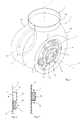
- a scroll type manifold is generally designated 1 and is arranged so as to constitute the housing of a radial impeller 2 of a fan, which is only schematically illustrated and which is able to be rotated by a motor 3 about an axis of rotation which is designated X.
- the manifold 1 and the motor 3 are configured so as to be mutually connected by a connection system which is constructed in accordance with the present invention.
- a delivery cross-section 5 in which the delivery flow direction, which is indicated by the axis Y of the Figures, is directed substantially perpendicularly relative to the axis X.
- the manifold 1 is further constructed as two manifold half-shells, which are designated 1a, 1b, respectively, and which can be connected together in a manner known per se in a connection plane.
- the half-shells are formed in a practically specularly symmetrical manner with respect to the connection plane, the plane therefore defining a median plane of substantial symmetry.
- each half-shell 1a, 1b comprises a respective semi-cylindrical nozzle portion 5a, those portions together defining the delivery nozzle which is able to be connected, to a pipe, for example, of an extractor hood (both not illustrated), so as to direct the flow drawn in by the ventilation unit in the direction of the discharge of the hood.
- a main intake cross-section 6 of the fan comprising a lateral opening 6a which is coaxial with the axis X of the impeller.
- a flange 7 for supporting the impeller/motor unit which is capable of disengageable connection with respect to the body of the half-shell 1b.
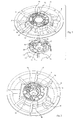
- the flange 7 comprises an external annular frame 8, in which there are provided holes 8a for fixing the flange to the body of the manifold, and a central hub portion 9 which is connected to the frame 8 by a plurality of strut-like elements 10.
- the motor 3 can be supported on the flange 7 with the connection system of the invention, described below in detail, the motor being able to be both arranged inside the manifold, as in the example described, and arranged outside the manifold, both configurations being possible with the above-mentioned connection system.
- connection and support means which, according to a main feature of the invention, are able to bring about a bayonet type connection between the mutually connected portions.
- the bayonet type connection means are provided between the central portion 9 of the flange 7 and a cover 3a of the motor 3 which can be fitted to each other coaxially.
- the above-mentioned bayonet type connection is brought about by cooperation between at least a first connection element formed on the flange portion 9 and at least a respective second connection element formed on the cover 3a of the motor.
- connection between the flange and the motor is brought about by means of cooperation between three different pairs of first and second connection elements, the first elements, similarly to the second elements, of the respective plurality being arranged with regular angular spacing between them, that is to say, angled at 120° relative to each other, on the respective flange and motor portion.
- first and second connection elements the first elements, similarly to the second elements, of the respective plurality being arranged with regular angular spacing between them, that is to say, angled at 120° relative to each other, on the respective flange and motor portion.
- Each first connection element comprises a first seat 11 and a second seat 12 which are formed in the central portion 9 of the flange and which are preferably constructed as axial through-holes through the flange.
- Those seats communicate with each other and extend circumferentially in the flange 7, one in continuation of the other, the seat 12 being developed in the form of an arcuate opening, whose curved profile is concentric relative to the axis X, as clearly illustrated in Figure 2 .
- Each second connection element comprises a first extension piece 14 which projects from a base surface 15 of the cover, the extension piece being formed as a wall which has an arcuate profile and which is developed along a circumferential arc which is concentric relative to the axis X.
- the extension piece 14 continues with a second extension piece 16 which extends substantially at right-angles, in a radial direction with respect to the cover. Both the extension pieces are further connected, at one end of the circumferentially developed curvilinear profile thereof, by another wall 17 which projects from the base 15.
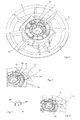
- the pair of extension pieces 14, 16 are selected to have such a shape as to be received with limited play through the opening of the seat 11, during relative axial movement between the cover of the motor and the flange, coaxially relative to the axis X, in order to be subsequently guided during relative rotational movement (about the axis X) with respect to the seats, during which the extension piece 14 is slidingly guided in the opening of the seat 12, as far as a position in which the flange portion which is adjacent to that seat and which is designated 18 is interposed between opposing surfaces of the cover base and the second extension piece, respectively, so as to bring about a relative axial retention action between the cover and the flange.
- first axial engagement movement followed by the second relative rotational movement between the flange and the cover are such that a bayonet type connection is brought about between the portions in relative engagement.
- relative disconnection is brought about by means of a first inverted rotation between the flange and the cover (until the second extension piece is disengaged from the second seat), followed by the disengagement in an axial direction of the pair of extension pieces from the first seat, thereby allowing the flange and cover of the motor to be moved apart from each other axially.
- That means comprises an engagement element which is generally designated 20 and which is able to engage respective portions of the cover and the flange with each other.
- That element is particularly constructed in the form of a resilient clip ( Figure 7 ) which has a pair of opposing ends 20a, 20b which can be resiliently deformed, thereby moving apart, when pressed between a pair of projections 21, 22 which project from the cover and the flange, respectively, in order to exert, owing to the resilient return forces caused by the deformation, a reciprocal retention action between the cover and the flange.
- the projection 21 is preferably provided on the second extension piece 16, as illustrated in Figure 4 , and is able to be radially aligned with the projection 22, which is provided on the flange, when the bayonet type connection described above is completely brought about between the cover and the flange.
- Respective pairs of reliefs 21a, 22a can further be associated with each of the projections 21, 22 and have the function of retaining the clip 20 in position when it is engaged in order to act counter to disengagement from the engagement position brought about.
- the invention thereby achieves the objects set out and provides a number of advantages over known solutions.
- connection system includes in particular the advantage linked to the greater ease and rapidity of the connection system over known solutions, which allows the operator to engage and disengage the motor quickly with respect to the manifold, with a simple and reliable connection and without requiring specific equipment or additional fixing elements with respect to the connected portions, as is the case, for example, with screw type fixing systems.
Landscapes
- Engineering & Computer Science (AREA)
- Mechanical Engineering (AREA)
- General Engineering & Computer Science (AREA)
- Structures Of Non-Positive Displacement Pumps (AREA)
- Superstructure Of Vehicle (AREA)
Applications Claiming Priority (1)
| Application Number | Priority Date | Filing Date | Title |
|---|---|---|---|
| ITPD20070074 ITPD20070074A1 (it) | 2007-03-06 | 2007-03-06 | Sistema di accoppiamento e supporto di motori su collettori a chiocciola di elettro-ventilatori, in particolare per l'impiego in cappe aspiranti |
Publications (1)
| Publication Number | Publication Date |
|---|---|
| EP1967743A2 true EP1967743A2 (de) | 2008-09-10 |
Family
ID=39563276
Family Applications (1)
| Application Number | Title | Priority Date | Filing Date |
|---|---|---|---|
| EP20080151216 Withdrawn EP1967743A2 (de) | 2007-03-06 | 2008-02-08 | System zum Anschließen von Motoren an und zum Abstützen auf spiralförmigen Verteilern von elektrischen Ventilatoren, insbesondere zur Verwendung in Abzugshauben |
Country Status (3)
| Country | Link |
|---|---|
| EP (1) | EP1967743A2 (de) |
| IT (1) | ITPD20070074A1 (de) |
| RU (1) | RU2008108714A (de) |
Cited By (2)
| Publication number | Priority date | Publication date | Assignee | Title |
|---|---|---|---|---|
| EP2338581A1 (de) * | 2009-12-22 | 2011-06-29 | ebm-papst Mulfingen GmbH & Co. KG | Lüftereinheit für Filterlüfter |
| DE102019129588A1 (de) * | 2019-11-04 | 2021-05-06 | Miele & Cie. Kg | Gebläse, umfassend ein Gehäuse und einen Motor |
-
2007
- 2007-03-06 IT ITPD20070074 patent/ITPD20070074A1/it unknown
-
2008
- 2008-02-08 EP EP20080151216 patent/EP1967743A2/de not_active Withdrawn
- 2008-03-05 RU RU2008108714/06A patent/RU2008108714A/ru not_active Application Discontinuation
Cited By (3)
| Publication number | Priority date | Publication date | Assignee | Title |
|---|---|---|---|---|
| EP2338581A1 (de) * | 2009-12-22 | 2011-06-29 | ebm-papst Mulfingen GmbH & Co. KG | Lüftereinheit für Filterlüfter |
| US8821129B2 (en) | 2009-12-22 | 2014-09-02 | Ebm-Papst Mulfingen Gmbh & Co. Kg | Fan unit for filter fans |
| DE102019129588A1 (de) * | 2019-11-04 | 2021-05-06 | Miele & Cie. Kg | Gebläse, umfassend ein Gehäuse und einen Motor |
Also Published As
| Publication number | Publication date |
|---|---|
| ITPD20070074A1 (it) | 2008-09-07 |
| RU2008108714A (ru) | 2009-09-10 |
Similar Documents
| Publication | Publication Date | Title |
|---|---|---|
| CN102102676B (zh) | 过滤器式风扇的风扇单元 | |
| EP2116725B1 (de) | Peristaltische Pumpe mit abnehmbarem Rohr | |
| CN108361832B (zh) | 一种空调 | |
| CN107255080B (zh) | 能够被安装在各种构造中的低轮廓泵 | |
| JP5902777B2 (ja) | 真空ポンプ及び真空ポンプを有する装置 | |
| JPH03212244A (ja) | スナップ式集合ハウジング | |
| EP1967743A2 (de) | System zum Anschließen von Motoren an und zum Abstützen auf spiralförmigen Verteilern von elektrischen Ventilatoren, insbesondere zur Verwendung in Abzugshauben | |
| US20160177972A1 (en) | Extraction hood | |
| EP1930601A2 (de) | Lüftergehäuse für eine Absaughaube | |
| RU2604979C2 (ru) | Вентилятор, а также соответствующий опорный элемент | |
| EP1967740A2 (de) | Verteiler, insbesondere spiralförmiger Verteiler für Lüfter zur Verwendung in Abzugshauben | |
| CN111365765A (zh) | 空调器室内机 | |
| WO2025200701A1 (zh) | 一种风扇模组及服务器 | |
| CN215571246U (zh) | 一种壳体机构及暖风机 | |
| US11959490B2 (en) | Ceiling fan with a blade connection assembly | |
| EP2336638B1 (de) | Verbindungssytem einer Ventilgruppe mit einer Gebläsevorrichtung einer Brenngas-Luft-Mischeinrichtung für Heizgeräte und ähnliche Vorrichtungen | |
| JP4763823B2 (ja) | 空気調和機の室外機及びその製造方法 | |
| CN212274097U (zh) | 一种蜗壳组件及空调器 | |
| CN212615480U (zh) | 蜗壳组件及风管机 | |
| JP6010338B2 (ja) | ブロワ | |
| JP7321763B2 (ja) | ブロワ装置 | |
| CN213713256U (zh) | 一种空调风机组件及空调器 | |
| CN111351086B (zh) | 蒸汽发生器安装组件和吸油烟机 | |
| CN115149750A (zh) | 马达及马达的组装方法 | |
| CN221400978U (zh) | 风机及其吸油烟机 |
Legal Events
| Date | Code | Title | Description |
|---|---|---|---|
| PUAI | Public reference made under article 153(3) epc to a published international application that has entered the european phase |
Free format text: ORIGINAL CODE: 0009012 |
|
| AK | Designated contracting states |
Kind code of ref document: A2 Designated state(s): AT BE BG CH CY CZ DE DK EE ES FI FR GB GR HR HU IE IS IT LI LT LU LV MC MT NL NO PL PT RO SE SI SK TR |
|
| AX | Request for extension of the european patent |
Extension state: AL BA MK RS |
|
| STAA | Information on the status of an ep patent application or granted ep patent |
Free format text: STATUS: THE APPLICATION IS DEEMED TO BE WITHDRAWN |
|
| 18D | Application deemed to be withdrawn |
Effective date: 20130903 |