EP1967825A2 - Échelle de valeur absolue et procédé de calcul de valeur absolue - Google Patents
Échelle de valeur absolue et procédé de calcul de valeur absolue Download PDFInfo
- Publication number
- EP1967825A2 EP1967825A2 EP08151373A EP08151373A EP1967825A2 EP 1967825 A2 EP1967825 A2 EP 1967825A2 EP 08151373 A EP08151373 A EP 08151373A EP 08151373 A EP08151373 A EP 08151373A EP 1967825 A2 EP1967825 A2 EP 1967825A2
- Authority
- EP
- European Patent Office
- Prior art keywords
- scale
- side coil
- coil pattern
- slider
- absolute value
- Prior art date
- Legal status (The legal status is an assumption and is not a legal conclusion. Google has not performed a legal analysis and makes no representation as to the accuracy of the status listed.)
- Withdrawn
Links
- 238000000034 method Methods 0.000 title claims description 43
- 238000006073 displacement reaction Methods 0.000 claims description 244
- 238000002474 experimental method Methods 0.000 claims description 23
- 239000011295 pitch Substances 0.000 abstract description 114
- 239000010410 layer Substances 0.000 description 32
- 238000001514 detection method Methods 0.000 description 23
- 230000008878 coupling Effects 0.000 description 14
- 238000010168 coupling process Methods 0.000 description 14
- 238000005859 coupling reaction Methods 0.000 description 14
- 238000010030 laminating Methods 0.000 description 14
- 238000004519 manufacturing process Methods 0.000 description 13
- 208000032365 Electromagnetic interference Diseases 0.000 description 9
- 238000010586 diagram Methods 0.000 description 9
- RYGMFSIKBFXOCR-UHFFFAOYSA-N Copper Chemical compound [Cu] RYGMFSIKBFXOCR-UHFFFAOYSA-N 0.000 description 6
- 239000011889 copper foil Substances 0.000 description 6
- 239000000853 adhesive Substances 0.000 description 4
- 230000001070 adhesive effect Effects 0.000 description 4
- 230000002411 adverse Effects 0.000 description 4
- 238000007796 conventional method Methods 0.000 description 4
- 230000000694 effects Effects 0.000 description 4
- 239000002344 surface layer Substances 0.000 description 4
- 238000004364 calculation method Methods 0.000 description 3
- NAWXUBYGYWOOIX-SFHVURJKSA-N (2s)-2-[[4-[2-(2,4-diaminoquinazolin-6-yl)ethyl]benzoyl]amino]-4-methylidenepentanedioic acid Chemical compound C1=CC2=NC(N)=NC(N)=C2C=C1CCC1=CC=C(C(=O)N[C@@H](CC(=C)C(O)=O)C(O)=O)C=C1 NAWXUBYGYWOOIX-SFHVURJKSA-N 0.000 description 2
- 238000001459 lithography Methods 0.000 description 2
- 239000000463 material Substances 0.000 description 2
- 238000000059 patterning Methods 0.000 description 1
Images







Classifications
-
- G—PHYSICS
- G01—MEASURING; TESTING
- G01D—MEASURING NOT SPECIALLY ADAPTED FOR A SPECIFIC VARIABLE; ARRANGEMENTS FOR MEASURING TWO OR MORE VARIABLES NOT COVERED IN A SINGLE OTHER SUBCLASS; TARIFF METERING APPARATUS; MEASURING OR TESTING NOT OTHERWISE PROVIDED FOR
- G01D5/00—Mechanical means for transferring the output of a sensing member; Means for converting the output of a sensing member to another variable where the form or nature of the sensing member does not constrain the means for converting; Transducers not specially adapted for a specific variable
- G01D5/12—Mechanical means for transferring the output of a sensing member; Means for converting the output of a sensing member to another variable where the form or nature of the sensing member does not constrain the means for converting; Transducers not specially adapted for a specific variable using electric or magnetic means
- G01D5/14—Mechanical means for transferring the output of a sensing member; Means for converting the output of a sensing member to another variable where the form or nature of the sensing member does not constrain the means for converting; Transducers not specially adapted for a specific variable using electric or magnetic means influencing the magnitude of a current or voltage
- G01D5/20—Mechanical means for transferring the output of a sensing member; Means for converting the output of a sensing member to another variable where the form or nature of the sensing member does not constrain the means for converting; Transducers not specially adapted for a specific variable using electric or magnetic means influencing the magnitude of a current or voltage by varying inductance, e.g. by a movable armature
- G01D5/204—Mechanical means for transferring the output of a sensing member; Means for converting the output of a sensing member to another variable where the form or nature of the sensing member does not constrain the means for converting; Transducers not specially adapted for a specific variable using electric or magnetic means influencing the magnitude of a current or voltage by varying inductance, e.g. by a movable armature by influencing the mutual induction between two or more coils
- G01D5/2086—Mechanical means for transferring the output of a sensing member; Means for converting the output of a sensing member to another variable where the form or nature of the sensing member does not constrain the means for converting; Transducers not specially adapted for a specific variable using electric or magnetic means influencing the magnitude of a current or voltage by varying inductance, e.g. by a movable armature by influencing the mutual induction between two or more coils by movement of two or more coils with respect to two or more other coils
-
- G—PHYSICS
- G01—MEASURING; TESTING
- G01D—MEASURING NOT SPECIALLY ADAPTED FOR A SPECIFIC VARIABLE; ARRANGEMENTS FOR MEASURING TWO OR MORE VARIABLES NOT COVERED IN A SINGLE OTHER SUBCLASS; TARIFF METERING APPARATUS; MEASURING OR TESTING NOT OTHERWISE PROVIDED FOR
- G01D1/00—Measuring arrangements giving results other than momentary value of variable, of general application
- G01D1/16—Measuring arrangements giving results other than momentary value of variable, of general application giving a value which is a function of two or more values, e.g. product or ratio
-
- G—PHYSICS
- G01—MEASURING; TESTING
- G01D—MEASURING NOT SPECIALLY ADAPTED FOR A SPECIFIC VARIABLE; ARRANGEMENTS FOR MEASURING TWO OR MORE VARIABLES NOT COVERED IN A SINGLE OTHER SUBCLASS; TARIFF METERING APPARATUS; MEASURING OR TESTING NOT OTHERWISE PROVIDED FOR
- G01D18/00—Testing or calibrating apparatus or arrangements provided for in groups G01D1/00 - G01D15/00
- G01D18/008—Testing or calibrating apparatus or arrangements provided for in groups G01D1/00 - G01D15/00 with calibration coefficients stored in memory
Definitions
- the present invention relates to an inductosyn type absolute value scale and an absolute value calculating method.
- An inductosyn type scale employed in machine tools and the like includes a rotary type (a rotary scale) and a linear type (a linear scale).
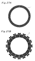
- the rotary scale is for detecting a rotation angle, and is configured of: a rotor on a rotating side having a rotor side coil pattern 1 folded in a zigzag manner and formed into an annular shape on the whole as shown in Fig. 27A ; and a stator on a fixed side having a stator side coil pattern 2 folded in a zigzag manner and formed into an annular shape on the whole as shown in Fig. 27B .
- the rotor and the stator are disposed to face each other so that the rotor side coil pattern 1 and the stator side coil pattern 2 can face each other.
- the linear scale is for detecting an amount of linear displacement, and is configured of: a slider on a sliding side having a slider side coil pattern folded in a zigzag manner and formed into a linear shape on the whole; and a scale on a fixed side having a scale side coil pattern folded in a zigzag manner and formed into a linear shape on the whole.
- the slider and the scale are disposed to face each other so that the slider side coil pattern and the scale side coil pattern can face each other.
- a rotary absolute value scale capable of detecting an absolute value of a rotation angle (an absolute angle) and a linear absolute value scale capable of detecting an absolute value of an amount of linear displacement (an absolute amount of displacement) are also developed today as absolute value scales obtained by applying the inductosyn type rotary scale and the inductosyn type linear scale as described above.
- the rotary absolute value scale is configured of: a rotor on a rotating side having two rotor side coil patterns 5 and 6 with different pitches which are folded in a zigzag manner and formed into annular shapes on the whole as shown in Fig. 29A ; and a stator on a fixed side having two stator side coil patterns 7 and 8 with different pitches which are folded in a zigzag manner and formed into annular shapes on the whole as shown in Fig. 29B .
- the rotor and the stator are disposed to face each other so that the rotor side coil patterns 5 and 6 can face the stator side coil patterns 7 and 8, respectively.
- the rotor side coil patterns 5 and 6 are provided with different pitches Pm [degrees] and Ps [degrees] (where Ps ⁇ Pm ), respectively, and are formed in the same plane.
- the stator side coil patterns 7 and 8 are also provided with different pitches Pm' [degrees] and Ps' [degrees] (where Ps' ⁇ Pm' ) , respectively, corresponding to the pitches Pm and Ps of the rotor side coil patterns 5 and 6, and are formed in the same plane.
- the stator side coil patterns 7 and 8 are formed on a stator 9 by attaching a copper foil onto a surface of a base member 10 with an insulating member 11 interposed therebetween, and then processing this copper foil by use of lithography or the like to form predetermined coil patterns.
- a wiring groove 14 is formed on the base member 10 so that the stator side coil patterns 7 and 8 are electrically connected to an external wire 15 through an internal wire 13 that is provided in this wiring groove 14.
- a secondary coil 12 of a transformer 16 is also provided in the wiring groove 14 formed on the base member 10.
- the rotor has a configuration similar to the stator, and is obtained by forming the rotor side coil patterns 5 and 6 by use of a copper foil attached onto a base member with an insulating member interposed therebetween.
- an internal wire and a primary coil of the transformer 16 are provided in a wiring groove that is formed on the base member.
- the linear absolute value scale is configured of: a slider on a sliding side having two slider side coil patterns 21 and 22 with different pitches which are folded in a zigzag manner and formed into linear shapes on the whole as shown in Fig. 31A ; and a scale on a fixed side having two scale side coil patterns 23 and 24 with different pitches which are folded in a zigzag manner and formed into linear shapes on the whole as shown in Fig. 31B .
- the slider and the scale are disposed to face each other so that the slider side coil patterns 21 and 22 can face the scale side coil patterns 23 and 24, respectively.
- the scale side coil patterns 23 and 24 are provided with different pitches Pm [mm] and Ps [mm] (where Ps ⁇ Pm ) , respectively, and the slider side coil patterns 21 and 22 are also provided with different pitches Pm' [degrees] and Ps' [degrees] (where Ps' ⁇ Pm' ), respectively corresponding to the pitches Pm and Ps of the scale side coil patterns 23 and 24, which are formed in the same plane.
- the slider side coil patterns 21 and 22 are formed on a slider 25 by attaching a copper foil onto a surface of a base member 26 with an insulating member 27 interposed therebetween and then by processing this copper foil to form predetermined coil patterns by use of lithography or the like.
- a wiring groove 28 is formed on the base member 26 so that the slider side coil patterns 21 and 22 can be electrically connected to an external wire 30 through an internal wire 29 that is provided in this wiring groove 28.
- the scale is configured as similar to the slider by forming the scale side coil patterns 23 and 24 by use of a copper foil attached onto a base member with an insulating member interposed therebetween.
- the scale side coil patterns 23 and 24 are electrically connected to an external wire through an internal wire that is provided in a wiring groove formed on the base member.
- the rotor side coil patterns 5 and 6 are formed in the same plane while the stator side coil patterns 7 and 8 are also formed in the same plane. Accordingly, in order to avoid an increase in the size of the entire absolute value scale, it is inevitable to reduce the space occupied by each of the coil patterns 5, 6, 7, and 8 (the lengths in a radial direction of each of the coil patterns 5, 6, 7, and 8). As a consequence, detection accuracy is more likely to be affected by manufacturing variation among the absolute value scales, and thus stable detection accuracy is difficult to obtain.
- the slider side coil patterns 21 and 22 are formed in the same plane while the scale side coil patterns 23 and 24 are also formed in the same plane. Accordingly, in order to avoid an increase in the size of the entire absolute value scale, it is inevitable to reduce the space occupied by each of the coil patterns 21, 22, 23, and 24 (the lengths in a width direction of each of the coil patterns 21, 22, 23, and 24) . As a consequence, detection accuracy is prone to be affected by manufacturing variation among the absolute value scales, and thus stable detection accuracy is difficult to obtain.
- An object of the present invention is to provide rotary and linear absolute value scales capable of increasing space occupied by each coil pattern (lengths in a radial direction and a width direction of each coil pattern) without increasing the size of the entire absolute value scales, and also capable of easily and reliably calculating the absolute angle and the absolute amount of displacement with the absolute value scales.
- an absolute value scale provides an absolute value scale including a slider having multiple slider side coil patterns each provided with a different pitch and a scale having multiple scale side coil patterns each provided with a different pitch where the slider and the scale are disposed to face each other so that the slider side coil patterns and the scale side coil patterns can face one another, in which the slider side coil patterns are laminated, and the scale side coil patterns are laminated.
- the absolute value scale is any of a rotary absolute value scale and a linear absolute value scale.
- the slider side coil patterns correspond to any of stator side coil patterns of the rotary absolute value scale and slider side coil patterns of the linear absolute value scale.
- the slider corresponds to any of a stator of the rotary absolute value scale and a slider of the linear absolute value scale.
- the scale side coil patterns corresponds to any of rotor side coil patterns of the rotary absolute value scale and scale side coil patterns of the linear absolute value scale.
- the scale corresponds to any of a rotor of the rotary absolute value scale and a scale of the linear absolute value scale.
- an absolute value scale according to a second aspect of the preset invention provides the absolute value scale of the first aspect, which includes feeding means for supplying alternating currents to each of the slider side coil patterns of the slider at different timings.
- an absolute value scale provides the absolute value scale of the first aspect, which includes feeding means for supplying alternating currents having different frequencies to each of the slider side coil patterns of the slider, and filters provided on each of output ends of the scale side coil patterns of the scale and configured to cut off a voltage having a frequency different from the frequency of an original induced voltage in each of the scale side coil patterns.
- an absolute value scale according to a fourth aspect of the present invention provides the absolute value scale of the third aspect, in which the feeding means supplies the alternating currents to each of the slider side coil patterns of the slider at different timings.
- an absolute value scale provides the absolute value scale of any of the first to fourth aspect.
- the slider side coil patterns correspond to stator side coil patterns of the rotary absolute value scale; the slider corresponds to a stator of the rotary absolute value scale; the scale side coil patterns correspond to rotor side coil patterns of the rotary absolute value scale; and the scale corresponds to a rotor of the rotary absolute value scale.
- the rotor includes a first rotor side coil pattern and a second rotor side coil pattern having mutually different pitches, and the stator includes a first stator side coil pattern and a second stator side coil pattern each provided with a different pitch.
- the slider side coil patterns correspond to slider side coil patterns of the linear absolute value scale
- the slider corresponds to a slider of the linear absolute value scale
- the scale side coil patterns correspond to scale side coil patterns of the linear absolute value scale
- the scale corresponds to a scale of the linear absolute value scale.
- the slider includes a first slider side coil pattern and a second slider side coil pattern each provided with a different pitch
- the scale includes a first scale side coil pattern and a second scale side coil pattern each provided with a different pitch.
- an absolute value scale provides the absolute value scale of the fifth aspect, in which, in the case where the absolute value scale is the rotary absolute value scale, the operating means corrects both of the detected angles Om and Os to become equal to 0° when the absolute angle of the rotor is equal to 0°, according to deviation amounts of the detected angles Om and Os from 0° obtained by a preliminary experiment when the absolute angle of the rotor is equal to 0°.
- the operating means corrects both of the detected amounts of displacement Om and Os to become equal to 0 mm when the absolute amount of displacement of the slider is equal to 0 mm, according to deviation amounts of the detected amounts of displacement Om and Os from 0 mm obtained by a preliminary experiment when the absolute amount of displacement of the slider is equal to 0 mm.
- an absolute value scale provides an absolute value scale including a slider having a first slider side coil pattern and a second slider coil pattern each provided with a different pitch and a scale having a first scale side pattern and a second scale side coil pattern each provided with a different pitch where the slider and the scale are disposed to face each other so that the first and second slider side coil patterns and the first and second scale side coil patterns can face one another.
- the absolute scale is a rotary absolute scale
- the first side coil pattern and the second slider side coil pattern respectively correspond to a first stator side coil pattern and a second stator side coil pattern of the rotary absolute value scale
- the slider corresponds to a stator of the rotary absolute value scale
- the first scale side coil pattern and the second scale side coil pattern respectively correspond to a first rotor side coil pattern and a second rotor side coil pattern of the rotary absolute value scale
- the scale corresponds to a rotor of the rotary absolute value scale.
- the absolute scale is a linear absolute scale
- the first slider side coil pattern and the second slider side coil pattern respectively correspond to a first slider side coil pattern and a second scale side coil pattern of the linear absolute value scale
- the slider corresponds to a slider of the linear absolute value scale
- the first scale side coil pattern and a second scale side coil pattern respectively correspond to a first scale side coil pattern and a second scale side coil pattern of the linear absolute value scale
- the scale corresponds to a scale of the linear absolute value scale.
- an absolute value scale provides the absolute value scale of the seventh aspect, in which, in the case where the absolute value scale is the rotary absolute value scale, the operating means corrects both of the detected angles Om and Os to 0° when the absolute angle of the rotor is equal to become equal to 0°, according to deviation amounts of the detected angles Om and Os from 0° obtained by a preliminary experiment when the absolute angle of the rotor is equal to 0°.
- the operating means corrects both of the detected amounts of displacement Om and Os to become equal to 0 mm when the absolute amount of displacement of the slider is equal to 0 mm, according to deviation amounts of the detected amounts of displacement Om and Os from 0 mm obtained by a preliminary experiment when the absolute amount of displacement of the slider is equal to 0 mm obtained by a preliminary experiment.
- a method of calculating an absolute value provides a method of calculating an absolute value of an amount of displacement of a slider in an absolute value scale including the slider having a first slider side coil pattern and a second slider coil pattern each provided with a different pitch and a scale having a first scale side pattern and a second scale side coil pattern each provided with a different pitch where the slider and the scale are disposed to face each other so that the first and second slider side coil patterns and the first and second scale side coil patterns can face one another.
- the absolute scale is a rotary absolute scale
- the first side coil pattern and the second slider side coil pattern respectively correspond to a first stator side coil pattern and a second stator side coil pattern of the rotary absolute value scale
- the slider corresponds to a stator of the rotary absolute value scale
- the first scale side coil pattern and the second scale side coil pattern respectively correspond to a first rotor side coil pattern and a second rotor side coil pattern of the rotary absolute value scale
- the scale corresponds to a rotor of the rotary absolute value scale
- the absolute value of the amount of displacement of the slider corresponds to an absolute angle of the rotor of the rotary absolute value scale.
- the absolute scale is a linear absolute scale
- the first slider side coil pattern and the second slider side coil pattern respectively correspond to a first slider side coil pattern and a second scale side coil pattern of the linear absolute value scale
- the slider corresponds to a slider of the linear absolute value scale
- the first scale side coil pattern and a second scale side coil pattern respectively correspond to a first scale side coil pattern and a second scale side coil pattern of the linear absolute value scale
- the scale corresponds to a scale of the linear absolute value scale
- the absolute value of the amount of displacement of the slider corresponds to an absolute amount of displacement of the slider of the linear absolute value scale.
- a method of calculating an absolute value according to a tenth aspect of the present invention provides the method of calculating an absolute value of the ninth aspect, in which, in the case where the absolute value scale is the rotary absolute value scale, both of the detected angles Om and Os to 0 are corrected to become 0° when the absolute angle of the rotor is equal to 0°, according to deviation amounts of the detected angles Om and Os from 0° obtained by a preliminary experiment when the absolute angle of the rotor is equal to 0°.
- both of the detected amounts of displacement Om and Os are corrected to become 0 mm when the absolute amount of displacement of the slider is equal to 0 mm, according to deviation amounts of the detected amounts of displacement Om and Os from 0 mm obtained by a preliminary experiment when the absolute amount of displacement of the slider is equal to 0 mm.
- the multiple slider side coil patterns are laminated and the multiple scale side coil patterns are also laminated. Accordingly, unlike a conventional case of providing multiple coil patterns in the same plane, it is possible to increase space occupied by each of the coil patterns (lengths in a radial direction of the respective coil patterns) without increasing the size of the entire absolute value scale. As a consequence, it is possible to reduce an adverse effect attributable to manufacturing variation of the absolute value scale, and detection accuracy of the absolute amount of displacement of the slider (the absolute angle of the rotor of the rotary absolute value scale or the absolute amount of displacement of the linear absolute value scale) is thereby stabilized.
- the absolute value scale includes the feeding means for supplying alternating currents to each of the slider side coil patterns of the slider at different timings. Accordingly, even in the case of the structure formed by laminating the multiple slider side coil patterns and laminating the multiple scale side coil patterns, it is possible to ensure detection accuracy of the absolute amount of displacement of the slider (the absolute angle of the rotor of the rotary absolute value scale or the absolute amount of displacement of the linear absolute value scale) while reducing electromagnetic interferences between these layers.
- the absolute value scale includes the feeding means for supplying alternating currents having different frequencies to each of the slider side coil patterns of the slider, and the filters provided on each of output ends of the scale side coil patterns of the scale and configured to cut off a voltage having a frequency different from the frequency of an original induced voltage in each of the scale side coil patterns. Accordingly, even in the case of the structure formed by laminating the multiple slider side coil patterns and laminating the multiple scale side coil patterns, it is possible to ensure detection accuracy of the absolute amount of displacement of the slider (the absolute angle of the rotor of the rotary absolute value scale or the absolute amount of displacement of the linear absolute value scale) while reducing electromagnetic interferences between these layers.
- the feeding means supplies the alternating currents to each of the slider side coil patterns of the slider at different timings. Accordingly, it is possible to ensure detection accuracy of the absolute amount of displacement of the slider (the absolute angle of the rotor of the rotary absolute value scale or the absolute amount of displacement of the linear absolute value scale) more reliably while reducing electromagnetic interferences between these layers.
- the operating means corrects both of the detected angles Om and Os to 0° when the absolute angle of the rotor is equal to 0°, according to deviation amounts of the detected angles Om and Os from 0° obtained by a preliminary experiment when the absolute angle of the rotor is equal to 0°.
- the operating means corrects both of the detected amounts of displacement Om and Os to 0 mm when the absolute amount of displacement of the slider is equal to 0 mm, according to deviation amounts of the detected amounts of displacement Om and Os from 0 mm obtained by a preliminary experiment when the absolute amount of displacement of the slider is equal to 0 mm. Accordingly, even if the absolute value scale contains manufacturing variation, it is possible to ensure detection accuracy of the absolute angle of the rotor of the rotary absolute value scale or the absolute amount of displacement of the linear absolute value scale.
- the operating means corrects both of the detected angles Om and Os to become 0° when the absolute angle of the rotor is equal to 0°, according to deviation amounts of the detected angles Om and Os from 0° obtained by a preliminary experiment when the absolute angle of the rotor is equal to 0°.
- the operating means corrects both of the detected amounts of displacement Om and Os to become 0 mm when the absolute amount of displacement of the slider is equal to 0 mm, according to deviation amounts of the detected amounts of displacement Om and Os from 0 mm obtained by a preliminary experiment when the absolute amount of displacement of the slider is equal to 0 mm. Accordingly, even if the absolute value scale contains manufacturing variation, it is possible to ensure detection accuracy of the absolute angle of the rotor of the rotary absolute value scale or the absolute amount of displacement of the linear absolute value scale.
- both of the detected angles Om and Os to 0 are corrected to become 0° when the absolute angle of the rotor is equal to 0°, according to deviation amounts of the detected angles Om and Os from 0°obtained by a preliminary experiment when the absolute angle of the rotor is equal to 0°.
- both of the detected amounts of displacement Om and Os are corrected to become 0 mm when the absolute amount of displacement of the slider is equal to 0 mm, according to deviation amounts of the detected amounts of displacement Om and Os from 0 mm obtained by a preliminary experiment when the absolute amount of displacement of the slider is equal to 0 mm. Accordingly, even if the absolute value scale contains manufacturing variation, it is possible to ensure detection accuracy of the absolute angle of the rotor of the rotary absolute value scale or the absolute amount of displacement of the linear absolute value scale.
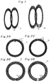
- Fig. 1 is a perspective view of rotor side coil patterns and stator side coil patterns of a rotary absolute value scale according to a first embodiment of the present invention.
- Figs. 2A to 2D are front views of the rotor side coil patterns and the stator side coil patterns.
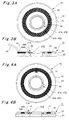
- Fig. 3A is a front view and Fig. 3B is a sectional side view of a stator constituting the rotary absolute value scale.
- Fig. 4A is a front view and Fig. 4B is a sectional side view of a rotor constituting the rotary absolute value scale.
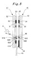
- Fig. 5 is a sectional side view showing an overall configuration of the rotary absolute value scale.
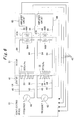
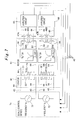
- Fig. 6 is a diagram showing a circuit configuration of the rotary absolute value scale.
- Fig. 7 is a diagram showing another circuit configuration of the rotary absolute value scale.
- Figs. 8 to 13 are graphs for explaining contents of a process for calculating an absolute angle by use of a scale control device of
- the rotary absolute value scale of the first embodiment is an absolute value scale applying an inductosyn type rotary scale capable of detecting an absolute value of a rotation angle (an absolute angle).
- the rotary absolute value scale is configured of: a rotor on a rotating side having a rotor side coil pattern 31 (a first rotor side coil pattern) and a rotor side coil pattern 32 (a second rotor side coil pattern) both of which are provided with different pitches, folded in a zigzag manner and formed into annular shapes on the whole as shown in Figs.
- stator on a fixed side having a stator side coil pattern 33 (a first stator side coil pattern) and a stator side coil pattern 34 (a second stator side coil pattern) both of which are provided with different pitches, folded in a zigzag manner and formed into annular shapes on the whole as shown in Figs. 1, 2B and 2D .
- the rotor and the stator are disposed to face each other so that the rotor side coil patterns 31 and 32 can face the stator side coil patterns 33 and 34.
- the rotor, the rotor side coil patterns, the stator, and the stator side coil patterns in this rotary absolute value scale respectively correspond to a scale, scale side coil patterns, a slider, and slider side coil patterns in a linear absolute value scale.
- the two rotor side coil patterns 31 and 32 are provided with different pitches Pm [degrees] and Ps [degrees] (where Ps ⁇ Pm ) , respectively, and the two stator side coil patterns 33 and 34 are also provided with different pitches Pm' [degrees] and Ps' [degrees] (where Ps' ⁇ Pm '), respectively, corresponding to the pitches Pm and Ps of the rotor side coil patterns 31 and 32.
- the two rotor side coil patterns 31 and 32 are laminated so as to be provided in different planes as shown in Fig. 1 , instead of being provided in the same plane as in the conventional technique.
- the two stator side coil patterns 33 and 34 are also laminated so as to be provided in different planes as shown in Fig. 1 , instead of being provided in the same plane as in the conventional technique.
- a stator 41 of this rotary absolute value scale is formed by fixing, by use of fixing means such as an adhesive, a multilayer printed circuit board 43 onto a surface of a base member 42 for ensuring strength.
- the stator side coil pattern 33 and the stator side coil pattern 34 are respectively printed on a first layer (a surface layer) and a second layer (an inner layer) of the multilayer printed circuit board 43, and the two layers are laminated.
- internal wires 44 are also printed on the layers of the multilayer printed circuit board 43, and the stator side coil patterns 33 and 34 are electrically connected to external wires 45 through these internal wires 44.
- the external wires 45 are electrically connected to a scale control device (see Figs. 6 and 7 ; to be described later in detail).
- secondary coils 48A and 48B of transformers 47A and 47B are located in a wiring groove 46 formed on the multilayer printed circuit board 43.
- a rotor 51 of this rotary absolute value scale is formed by fixing, by use of fixing means such as an adhesive, a multilayer printed circuit board 53 onto a surface of a base member 52 for ensuring strength.
- the rotor side coil pattern 31 and the rotor side coil pattern 32 are respectively printed on a first layer (a surface layer) and a second layer (an inner layer) of the multilayer printed circuit board 53, and the two layers are laminated.
- primary coils 58A and 58B of the transformers 47A and 47B are located in a wiring groove 56 formed on the multilayer printed circuit board 53.
- the rotor 51 and the stator 41 are disposed to face each other so that the rotor side coil patterns 31 and 32 can face the stator side coil patterns 33 and 34.
- the rotor 51 is fitted to a rotating shaft of a machine tool or the like and is rotated as indicated with an arrow A together with the rotating shaft.
- the stator 41 is fitted to a fixed part of the machine tool or the like.
- the primary coils 58 and the secondary coils 48 of the transformers 47 are also opposed to one another.
- the rotary absolute value scale may employ any of circuit configurations shown in Figs. 6 and 7 .
- a scale control device 61 serving as a calculating means as well as a feeding means, includes two alternating current sources 62 and 63.
- the alternating current source 62 is electrically connected to the stator side coil pattern 33 of the stator 41 through the external wire 45 and the internal wire 44, and is configured to supply an alternating current having a frequency f to this stator side coil pattern 33.
- the other alternating current source 63 is electrically connected to the stator side coil pattern 34 of the stator 41 through the external wire 45 and the internal wire 44, and is configured to supply an alternating current having a frequency f to this stator side coil pattern 34.
- the scale control device 61 supplies the alternating currents to each of the stator side coil patterns 33 and 34 of the stator 41 at different timings. Specifically, the electric supply from the alternating current source 62 to the stator side coil pattern 33, and the electric supply from the alternating current source 63 to the stator side coil pattern 34 are executed not simultaneously but at shifted timings.
- the primary coil 58A of the transformer 47A is electrically connected to the rotor side coil pattern 31 of the rotor 51 through the internal wire 64 (which is provided on each portion of the multilayer printed circuit board 53 of the rotor 51 in the form of a printed wire or the like).
- the primary coil 58B of the transformer 47B is electrically connected to the rotor side coil pattern 32 of the rotor 51 through the internal wire 64.
- an input end of an amplifier circuit 65 is electrically connected to the secondary coil 48A of the transformer 47A through the internal wire 44 and an input end of an amplifier circuit 66 is electrically connected to the secondary coil 48B of the transformer 47B through the internal wire 44.
- the amplifier circuits 65 and 66 are provided in the multilayer printed circuit board 43 of the stator 41. Output ends of the amplifier circuits 65 and 66 are electrically connected to the scale control device 61 through the external wires 45.
- an induced voltage (a voltage having the frequency f ) is generated on the rotor side coil pattern 31.
- This induced voltage is transmitted from the rotating side (the rotor side) to the fixed side (the stator side) through the transformer 47A incorporated respectively in the rotating side and the fixed side. Thereafter, the induced voltage transmitted to the fixed side is amplified by the amplifier circuit 65 and is then inputted to the scale control device 61.
- an induced voltage (a voltage having the frequency f ) is generated on the rotor side coil pattern 32.
- This induced voltage is transmitted from the rotating side (the rotor side) to the fixed side (the stator side) through the transformer 47B incorporated respectively in the rotating side and the fixed side. Thereafter, the induced voltage transmitted to the fixed side is amplified by the amplifier circuit 66 and is then inputted to the scale control device 61.
- the scale control device 61 calculates an absolute value of a rotation angle (an absolute angle) of the rotor 51 (such as the rotating shaft of the machine tool or the like joined to the rotor 51) based on the induced voltages inputted from the amplifier circuits 65 and 66, as will be described later in detail.
- a scale control device 71 serving as a calculating means as well as a feeding means, includes two alternating current sources 72 and 73.
- the alternating current source 72 is electrically connected to the stator side coil pattern 33 of the stator 41 through the external wire 45 and the internal wire 44, and is configured to supply an alternating current having a frequency fm to this stator side coil pattern 33.
- the other alternating current source 73 is electrically connected to the stator side coil pattern 34 of the stator 41 through the external wire 45 and the internal wire 44, and is configured to supply an alternating current having a frequency fs to this stator side coil pattern 34.
- the scale control device 71 supplies the alternating currents provided with the different frequencies fm and fs respectively to the stator side coil patterns 33 and 34 of the stator 41. Moreover, the scale control device 71 supplies the alternating currents to each of the stator side coil patterns 33 and 34 of the stator 41 at different timings. Specifically, the electric supply from the alternating current source 72 to the stator side coil pattern 33, and the electric supply from the alternating current source 73 to the stator side coil pattern 34 are executed not simultaneously but at shifted timings.
- An input end of a filter 74 is electrically connected to the rotor side coil pattern 31 of the rotor 51 through the internal wire 64 (which is provided on each portion of the multilayer printed circuit board 53 of the rotor 51 in the form of a printed wire or the like), and an input end of a filter 75 is electrically connected to the rotor side coil pattern 32 of the rotor 51 through the internal wire 64.
- the primary coil 58A of the transformer 47A is electrically connected to an output end of the filter 74 through the internal wire 64
- the primary coil 58B of the transformer 47B is electrically connected to an output end of the filter 75 through the internal wire 64.
- Each of the filters 74 and 75 are provided in the multilayer printed circuit board 53 of the rotor 51.
- the filter 74 cuts off the voltage having the frequency fs, while the other filter 75 cuts off the voltage having the frequency fm.
- the input end of the amplifier circuit 65 is electrically connected to the secondary coil 48A of the transformer 47A through the internal wire 44
- the input end of the amplifier circuit 66 is electrically connected to the secondary coil 48B of the transformer 47B through the internal wire 44.
- the amplifier circuits 65 and 66 are provided in the multilayer printed circuit board 43 of the stator 41.
- the output ends of the amplifier circuits 65 and 66 are electrically connected to the scale control device 71 through the external wires 45.
- the induced voltage (the voltage having the frequency fm ) is generated on the rotor side coil pattern 31.
- This induced voltage is transmitted from the rotating side (the rotor side) to the fixed side (the stator side) through the transformer 47A incorporated in the rotating side and the fixed side.
- the filter 74 is configured to cut off the voltage having the frequency fs, i.e. to cut off the voltage having the frequency different from the frequency fm of the original induced voltage in the rotor side coil pattern 31. Accordingly, the original induced voltage having the frequency fm, which is generated by the electromagnetic coupling between the stator side coil pattern 33 and the rotor side coil pattern 31, is not cut off but is passed through the filter 74 to be transmitted to the fixed side. Thereafter, the induced voltage transmitted to the fixed side is amplified by the amplifier circuit 65 and is then inputted to the scale control device 71.
- the induced voltage (the voltage having the frequency fs ) is generated on the rotor side coil pattern 32.
- This induced voltage is transmitted from the rotating side (the rotor side) to the fixed side (the stator side) through the transformer 47B incorporated in the rotating side and the fixed side.
- the filter 75 is configured to cut off the voltage having the frequency fm, i.e. to cut off the voltage having the frequency different from the frequency fs of the original induced voltage in the rotor side coil pattern 32. Accordingly, the original induced voltage having the frequency fs, which is generated by the electromagnetic coupling between the stator side coil pattern 34 and the rotor side coil pattern 32, is not cut off but is passed through the filter 75 to be transmitted to the fixed side.
- the induced voltage transmitted to the fixed side is amplified by the amplifier circuit 66 and is then inputted to the scale control device 71.
- the scale control device 71 calculates the absolute value of the rotation angle (the absolute angle) of the rotor 51 (such as the rotating shaft of the machine tool or the like joined to the rotor 51) based on the induced voltages inputted from the amplifier circuits 65 and 66, as will be described later in detail.
- Figs. 8 to 13 show an example where the pitch Pm of the rotor side coil pattern 31 is set to 72 [degrees] and the pitch Ps of the rotor side coil pattern 32 is set to 60 [degrees].
- the lateral axis indicates the rotation angle (the absolute angle) of the rotor 51 and the longitudinal axis indicates the values Om, Os, D, E , and Z relative to the rotation angle (the absolute angle).
- the value Om indicated with a solid line is the rotation angle of the rotor 51 detected by the rotor side coil pattern 31 having the pitch Pm
- the value Os indicated with a dashed line is the rotation angle of the rotor 51 detected by the rotor side coil pattern 32 having the pitch Ps.
- the scale control device 61 or 71 firstly finds the detected angle Om based on the induced voltage of the rotor side coil pattern 31 and then finds the detected angle Os based on the induced voltage of the rotor side coil pattern 32.
- the detected angle Om varies iteratively at a period of 72 [degrees] and forms a saw-tooth shape as shown in the drawing.
- the pitch Ps is set to 60 [degrees]
- the detected angle Os varies iteratively at a period of 60 [degrees] and forms a saw-tooth shape as shown in the drawing.
- positional relations between the rotor side coil patterns 31 and 32 and the stator side coil patterns 33 and 34 are set such that both of the detected angles Om and Os become equal to 0 [degrees] when the rotation angle (the absolute angle) of the rotor 51 is equal to 0 [degrees].
- the detected angles Om and Os do not become equal to 0 [degrees] as designed when the rotation angle (the absolute angle) of the rotor 51 is equal to 0 [degrees]
- some deviation is generated in the detected angles Om and Os.
- Such deviation may be attributable to rotational deviation of the rotor 51 relative to the stator 41 based on manufacturing variation of the rotary absolute value scale, for example.
- deviation amounts (an offset amount) for these detected angles Om and Os are obtained in advance by an experiment and are set in (inputted to and stored in) the scale control device 61 or 71. Then, according to the deviation amounts (the offset amount), the scale control device 61 or 71 corrects the detected angles Om and Os derived from the induced voltages. Specifically, the scale control device 61 or 71 corrects (offsets) so as to adjust both of the detected angles Om and Os to be equal to 0 [degrees] when the rotation angle (the absolute angle) of the rotor 51 is equal to 0 [degrees], by either adding or subtracting the deviation amounts (the offset amount) to or from the detected angles Om and Os derived from the induced voltages.
- the formula (2) is a modified form of the formula (1). Specifically, in a range of 360 [degrees], the number of pitches of the rotor side coil pattern 32 having the pitch Ps is set one pitch larger than the number of pitches of the rotor side coil pattern 31 having the pitch Pm. Naturally, the case of setting the pitch Pm equal to 72 [degrees] and the pitch Ps equal to 60 [degrees] satisfies the formulae (1) and (2). Accordingly, as can be seen in Figs.
- Cited below are examples of calculation of the absolute angle Z according to the illustrated example.
- the two rotor side coil patterns 31 and 32 are laminated and the two stator side coil patterns 33 and 34 are also laminated. Accordingly, unlike the conventional case of providing two coil patterns in the same plane, it is possible to increase space occupied by each of the coil patterns 31, 32, 33, and 34 (lengths in a radial direction of each of the coil patterns 31, 32, 33, and 34) without increasing the size of the entire rotary absolute value scale. As a consequence, it is possible to reduce an adverse effect attributable to manufacturing variation of the rotary absolute value scale, and detection accuracy of the absolute angle of the rotor 51 is thereby stabilized.
- the rotor 51 is formed by providing the two rotor side coil patterns 31 and 32 respectively on the layers of the multilayer printed circuit board 53 in the form of printed wires.
- the stator 41 is formed by providing the two stator side coil patterns 33 and 34 respectively on the layers of the multilayer printed circuit board 43 in the form of printed wires.
- the rotary absolute value scale includes the scale control device 61 (namely, the alternating current sources 62 and 63) for supplying the alternating currents to each of the stator side coil patterns 33 and 34 of the stator 41 at different timings. Accordingly, even with the structure formed by laminating the two rotor side coil patterns 31 and 32 and laminating the two stator side coil patterns 33 and 34, it is possible to ensure detection accuracy of the absolute angle of the rotor 51 while reducing electromagnetic interferences between these layers.
- the scale control device 61 namely, the alternating current sources 62 and 63
- the rotary absolute value scale includes: the scale control device 71 (namely, the alternating current sources 72 and 73) for supplying alternating currents of different frequencies fm and fs respectively to stator side coil patterns 33 and 34 of the stator 41; and the filters 74 and 75 respectively provided on the output ends of the rotor side coil patterns 31 and 32 of the rotor 51, configured to cut off the voltage having the frequency different from the frequency fm or fs of the original induced voltage in each of the rotor side coil patterns 31 and 32.
- the scale control device 71 namely, the alternating current sources 72 and 73
- the filters 74 and 75 respectively provided on the output ends of the rotor side coil patterns 31 and 32 of the rotor 51, configured to cut off the voltage having the frequency different from the frequency fm or fs of the original induced voltage in each of the rotor side coil patterns 31 and 32.
- the scale control device 71 (namely, the alternating current sources 72 and 73) supplies the alternating currents to each of the stator side coil patterns 33 and 34 of the stator 41 at different timings. Accordingly, it is possible to ensure detection accuracy of the absolute angle of the rotor 51 more reliably while reducing electromagnetic interferences between these layers. If the alternating currents are supplied to the stator side coil patterns 33 and 34 simultaneously, an electromagnetic interference may occur between the transformers 47A and 47B, for example. However, such an electromagnetic interference can be avoided by supplying the alternating currents to the stator side coil patterns 33 and 34 at different timings.
- the rotary absolute value scale includes the scale control device 61 or 71 that calculates the absolute angle Z of the rotor 51 in the following manner.
- the detected angle Om is found on the basis of the induced voltage of the rotor side coil pattern 31
- the detected angle Os is found on the basis of the induced voltage of the rotor side coil pattern 32
- the scale control device 61 or 71 corrects both of the detected angles Om and Os to become equal to 0° when the absolute angle of the rotor 51 is equal to 0°, according to the deviation amounts of the detected angles Om and Os from 0° obtained by a preliminary experiment when the absolute angle of the rotor 51 is equal to 0°. Accordingly, even if the rotary absolute value scale contains manufacturing variation, it is possible to ensure detection accuracy of the absolute angle of the rotor 51.
- Fig. 14 is a perspective view of slider side coil patterns and scale side coil patterns of a linear absolute value scale according to a second embodiment of the present invention.
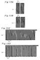
- Figs. 15A to 15D are front views of the slider side coil patterns and the scale side coil patterns.
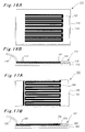
- Fig. 16A is a front view and Fig. 16B is a sectional side view of a slider constituting the linear absolute value scale.
- Fig. 17A is a front view and Fig. 17B is a sectional side view of a scale constituting the linear absolute value scale.
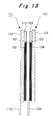
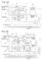
- Fig. 18 is a sectional side view showing an overall configuration of the linear absolute value scale.
- Fig. 19 is a diagram showing a circuit configuration of the linear absolute value scale.
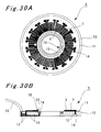
- Fig. 20 is a diagram showing another circuit configuration of the linear absolute value scale.
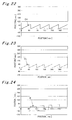
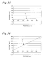
- Figs. 21 to 26 are graphs for explaining contents of a process for calculating an absolute value of displacement by use of a scale control device of the linear absolute value scale.
- the linear absolute value scale of the second embodiment is an absolute value scale applying an inductosyn type linear scale capable of detecting an absolute value of an amount of displacement (an absolute value of displacement).
- the linear absolute value scale is configured of: a slider on a sliding side having a slider side coil pattern 101 (a second slider side coil pattern) and another slider side coil pattern 102 (a first slider side coil pattern) both of which are provided with different pitches, which are folded in a zigzag manner and formed into linear shapes on the whole as shown in Figs.
- a scale on a fixed side having a scale side coil pattern 103 (a second scale side coil pattern) and another scale side coil pattern 104 (a first scale side coil pattern) both of which are provided with different pitches, which are folded in a zigzag manner and formed into linear shapes on the whole as shown in Figs. 1 , 15C and 15D .
- the slider and the scale are disposed to face each other so that the slider side coil patterns 101 and 102 can face the scale side coil patterns 103 and 104.
- the two scale side coil patterns 103 and 104 are provided with different pitches Ps [mm] and Pm [mm] (where Ps ⁇ Pm ), respectively, and the two slider side coil patterns 101 and 102 are also provided with different pitches Ps' [mm] and Pm' [mm] (where Ps' ⁇ Pm '), respectively, corresponding to the pitches Ps and Pm of the scale side coil patterns 103 and 104.
- the two slider side coil patterns 101 and 102 are laminated so as to be provided in different planes as shown in Fig. 14 , instead of being provided in the same plane as in the conventional technique.
- the two scale side coil patterns 103 and 104 are also laminated so as to be provided in different planes as shown in Fig. 14 , instead of being provided in the same plane as in the conventional technique.
- a slider 111 of this linear absolute value scale is formed by fixing, by use of fixing means such as an adhesive, a multilayer printed circuit board 113 onto a surface of a base member 112 for ensuring strength.
- the slider side coil pattern 101 and the slider side coil pattern 102 are respectively printed on a first layer (a surface layer) and a second layer (an inner layer) of the multilayer printed circuit board 113, and the two layers are laminated.
- internal wires 114 are also printed on the layers of the multilayer printed circuit board 113, and the slider side coil patterns 101 and 102 are electrically connected to external wires 115 through these internal wires 114.
- the external wires 115 are electrically connected to a scale control device (see Figs. 19 and 20 ; to be described later in detail).
- a scale 121 of this linear absolute value scale is formed by fixing, by use of fixing means such as an adhesive, a multilayer printed circuit board 123 onto a surface of a base member 122 for ensuring strength.
- the scale side coil pattern 103 and the scale side coil pattern 104 are respectively printed on a first layer (a surface layer) and a second layer (an inner layer) of the multilayer printed circuit board 123, and the two layers are laminated.
- internal wires 124 are also printed on the layers of the multilayer printed circuit board 123, and the scale side coil patterns 103 and 104 are electrically connected to external wires 125 through these internal wires 124.
- the external wires 125 are electrically connected to the scale control device (see Figs. 19 and 20 ; to be described later in detail).
- the slider 111 and the scale 121 are disposed to face each other so that the slider side coil patterns 101 and 102 can face the scale side coil patterns 103 and 104.
- the slider 111 is fitted to a linear motion shaft of a machine tool or the like and moves (slides) linearly in an orthogonal direction to a sheet face of Fig. 18 together with the linear motion shaft.
- the scale 121 is fitted to a fixed part of the machine tool or the like.
- the linear absolute value scale may employ any of circuit configurations shown in Figs. 19 and 20 .
- a scale control device 131 serving as a calculating means as well as a feeding means, includes two alternating current sources 132 and 133.
- the alternating current source 132 is electrically connected to the slider side coil pattern 101 of the slider 111 through the external wire 115 and the internal wire 114, and is configured to supply an alternating current having a frequency f to this slider side coil pattern 101.
- the other alternating current source 133 is electrically connected to the slider side coil pattern 102 of the slider 111 through the external wire 115 and the internal wire 114, and is configured to supply an alternating current having a frequency fto this slider side coil pattern 102.
- the scale control device 131 supplies the alternating currents to each of the slider side coil patterns 101 and 102 of the slider 111 at different timings. Specifically, the electric supply from the alternating current source 132 to the slider side coil pattern 101 and the electric supply from the alternating current source 133 to the slider side coil pattern 102 are executed not simultaneously but at shifted timings.
- An input end of an amplifier circuit 135 is electrically connected to the scale side coil pattern 103 of the scale 121 through the internal wire 124, and an input end of an amplifier circuit 136 is electrically connected to the scale side coil pattern 104 of the scale 121 through the internal wire 124.
- the amplifier circuits 135 and 136 are provided in the multilayer printed circuit board 123 of the scale 121. Output ends of the amplifier circuits 135 and 136 are electrically connected to the scale control device 131 through the external wires 125.
- an induced voltage (a voltage having the frequency f ) is generated on the scale side coil pattern 103.
- this induced voltage (the voltage having the frequency f ) is amplified by the amplifier circuit 135 and is then inputted to the scale control device 131.
- an induced voltage (a voltage having the frequency f ) is generated on the scale side coil pattern 104.
- the scale control device 131 calculates an absolute value of an amount of linear displacement (an absolute amount of displacement) of the slider 111 (such as the linear motion shaft of the machine tool or he like joined to the slider 111) based on the induced voltages inputted from the amplifier circuits 135 and 136, as will be described later in detail.
- a scale control device 141 serving as a calculating means as well as a feeding means, includes two alternating current sources 142 and 143.
- the alternating current source 142 is electrically connected to the slider side coil pattern 101 of the slider 111 through the external wire 115 and the internal wire 114, and is configured to supply an alternating current having a frequency fs to this slider side coil pattern 101.
- the other alternating current source 143 is electrically connected to the slider side coil pattern 102 of the slider 111 through the external wire 115 and the internal wire 114, and is configured to supply an alternating current having a frequency fm to this slider side coil pattern 102.
- the scale control device 141 supplies the alternating currents provided with the different frequencies fm and fs respectively to the slider side coil patterns 101 and 102 of the slider 111. Moreover, the scale control device 141 supplies the alternating currents to each of the slider side coil patterns 101 and 102 of the slider 111 at different timings. Specifically, the electric supply from the alternating current power unit 142 to the slider side coil pattern 101 and the electric supply from the alternating current 143 to the slider side coil pattern 102 are executed not simultaneously but at shifted timings.
- An input end of a filter 144 is electrically connected to the scale side coil pattern 103 of the scale 121 through the internal wire 124, and an input end of a filter 145 is electrically connected to the scale side coil pattern 104 of the scale 121 through the internal wire 124.
- the filters 144 and 145 are provided in the multilayer printed circuit board 123 of the scale 121. The filter 144 cuts off the voltage having the frequency fm while the other filter 145 cuts off the voltage having the frequency fs.
- the input end of the amplifier circuit 135 is electrically connected to an output end of the filter 144 through the internal wire 124
- the input end of the amplifier circuit 136 is electrically connected to an output end of the filter 145 through the internal wire 124.
- the amplifier circuits 135 and 136 are provided in the multilayer printed circuit board 123 of the scale 121.
- the output ends of the amplifier circuits 135 and 136 are electrically connected to the scale control device 141 through the external wires 125.
- the induced voltage (the voltage having the frequency fs ) is generated on the scale side coil pattern 103.
- This induced voltage is transmitted to the amplifier circuit 135 through the filter 144.
- the filter 144 is configured to cut off the voltage having the frequency fm, i.e. to cut off the voltage having the frequency different from the frequency fs of the original induced voltage in the scale side coil pattern 103. Accordingly, the original induced voltage having the frequency fs, which is generated by the electromagnetic coupling between the slider side coil pattern 101 and the scale side coil pattern 103, is not cut off but is passed through the filter 144 to be transmitted to the amplifier circuit 135. Thereafter, the induced voltage transmitted to the amplifier circuit 135 is amplified by the amplifier circuit 135 and is then inputted to the scale control device 141.
- the induced voltage (the voltage having the frequency fm ) is generated on the scale side coil pattern 104.
- This induced voltage is transmitted to the amplifier circuit 136 through the filter 145.
- the filter 145 is configured to cut off the voltage having the frequency fs, i.e. to cut off the voltage having the frequency different from the frequency fm of the original induced voltage in the scale side coil pattern 104. Accordingly, the original induced voltage having the frequency fm, which is generated by the electromagnetic coupling between the slider side coil pattern 102 and the scale side coil pattern 104, is not cut off but is passed through the filter 145 to be transmitted to the amplifier circuit 136. Thereafter, the induced voltage transmitted to the amplifier circuit 136 is amplified by the amplifier circuit 136 and is then inputted to the scale control device 141.
- the scale control device 141 calculates the absolute value of the amount of linear displacement (the absolute amount of displacement) of the slider 111 (such as the linear motion shaft of the machine tool or the like joined to the slider 111) based on the induced voltages inputted from the amplifier circuits 135 and 136, as will be described later in detail.
- Figs. 21 to 26 show an example where a detected amount of displacement L of the entire linear absolute value scale is set to 360 [mm], the pitch Pm of the scale side coil pattern 104 is set to 72 [mm], and the pitch Ps of the scale side coil pattern 103 is set to 60 [mm].
- the lateral axis indicates the absolute amount of linear displacement (the absolute amount of displacement) of the slider 111
- the longitudinal axis indicates the values Om, Os, D, E, and Z relative to the absolute amount of linear displacement (the absolute amount of displacement).
- the value Om indicated with a solid line is the amount of displacement of the slider 111 detected by the scale side coil pattern 104 having the pitch Pm
- the value Os indicated with a dashed line is the amount of displacement of the slider 111 detected by the scale side coil pattern 103 having the pitch Ps.
- the scale control device 131 or 141 firstly finds the detected amount of displacement Om based on the induced voltage of the scale side coil pattern 104, and then finds the detected angle Os based on the induced voltage of the scale side coil pattern 103.
- the pitch Pm is set to 72 [mm] in the illustrated example, the detected amount of displacement Om varies iteratively at a period of 72 [mm] and forms a saw-tooth shape as shown in the drawing. Meanwhile, since the pitch Ps is set to 60 [mm], the detected amount of displacement Os varies iteratively at a period of 60 [mm] and forms a saw-tooth shape as shown in the drawing.
- positional relations between the slider side coil patterns 101 and 102 and the scale side coil patterns 103 and 104 are set such that both of the detected amounts of displacement Om and Os become equal to 0 [mm] when the position (the absolute amount of displacement) of the slider 111 is equal to 0 [mm].
- the detected amounts of displacement Om and Os do not become equal to 0 [mm] as designed when the position (the absolute amount of displacement) of the slider 111 is equal to 0 [mm]
- some deviation is generated in the detected amounts of displacement Om and Os.
- Such deviation may be attributable to positional deviation of the slider 111 relative to the scale 121 based on manufacturing variation of the linear absolute value scale, for example.
- deviation amounts (an offset amount) for these detected amount of displacements Om and Os are obtained in advance by an experiment and is inputted to the scale control device 131 or 141. Then, according to the deviation amounts (the offset amount), the scale control device 131 or 141 corrects the detected amount of displacements Om and Os derived from the induced voltages. Specifically, the scale control device 131 or 141 corrects (offsets) so as to adjust both of the detected amounts of displacement Om and Os to be equal to 0 [mm] when the amount of linear displacement (the absolute amount of displacement) of the slider 111 is equal to 0 [mm], by either adding or subtracting the deviation amounts (the offset amount) to or from the detected amounts of displacement Om and Os derived from the induced voltages.
- the formula (8) is a modified form of the formula (7).
- the value L in the formulae (7) and (8) is the detected amount of displacement of the entire linear absolute value scale, which is set to 360 [mm] in the illustrated example.
- the number of pitches of the scale side coil pattern 103 having the pitch Ps is set one pitch larger than the number of pitches of the scale side coil pattern 104 having the pitch Pm.
- the scale control device 131 or 141 finds an absolute amount of displacement Z of the slider 111 by calculating the following formula (12) on the basis of the value E set by use of the formula (10) or (11), the pitch Ps , and the detected amount of displacement Om.
- Cited below are examples of calculation of the absolute amount of displacement Z according to the illustrated example.
- the two slider side coil patterns 101 and 102 are laminated and the two scale side coil patterns 103 and 104 are also laminated. Accordingly, unlike the conventional case of providing two coil patterns in the same plane, it is possible to increase space occupied by each of the coil patterns 101, 102, 103 and 104 (lengths in a radial direction of the respective coil patterns 101, 102, 103 and 104) without increasing the size of the entire linear absolute value scale. As a consequence, it is possible to reduce an adverse effect attributable to manufacturing variation of the linear absolute value scale, and detection accuracy of the absolute amount of displacement of the slider 111 is thereby stabilized.
- the slider 111 is formed by providing the two slider side coil patterns 101 and 102 on the layers of the multilayer printed circuit board 113 in the form of printed wires.
- the scale 121 is formed by providing the two scale side coil patterns 103 and 104 on the layers of the multilayer printed circuit board 123 in the form of printed wires.
- the linear absolute value scale includes the scale control device 131 (namely, the alternating current sources 132 and 133) for supplying the alternating currents to each of the slider side coil patterns 101 and 102 of the slider 111 at different timings. Accordingly, even with the structure formed by laminating the two slider side coil patterns 101 and 102 and laminating the two scale side coil patterns 103 and 104, it is possible to ensure detection accuracy of the absolute amount of displacement of the slider 111 while reducing electromagnetic interferences between these layers.
- the scale control device 131 namely, the alternating current sources 132 and 133
- the linear absolute value scale includes' the scale control device 141 (namely, the alternating current sources 142 and 143) configured to supply the alternating currents having the different frequencies fm and fs to the slider side coil patterns 101 and 102 of the stator 111; and the filters 144 and 145 respectively provided on the output ends of the scale side coil patterns 103 and 104 of the scale 121, configured to cut off the voltage having the frequency different from the frequency fm or fs of the original induced voltage in each of the scale side coil patterns 103 and 104 of the scale 102.
- the scale control device 141 namely, the alternating current sources 142 and 143
- the filters 144 and 145 respectively provided on the output ends of the scale side coil patterns 103 and 104 of the scale 121, configured to cut off the voltage having the frequency different from the frequency fm or fs of the original induced voltage in each of the scale side coil patterns 103 and 104 of the scale 102.
- the scale control device 141 (namely, the alternating current sources 142 and 143) supplies the alternating currents to each of the slider side coil patterns 101 and 102 of the slider 111 at different timings. Hence, it is possible to ensure detection accuracy of the absolute amount of displacement of the slider 111 more reliably while reducing electromagnetic interferences between these layers.
- the scale control device 131 or 141 corrects both of the detected amounts of displacement Om and Os to become equal to 0 mm when the absolute amount of displacement of the slider 111 is equal to 0 mm, according to the deviation amounts of the detected amounts of displacement Om and Os from 0 mm obtained by a preliminary experiment when the absolute amount of displacement of the slider 111 is equal to 0 mm. Accordingly, even if the linear absolute value scale contains manufacturing variation, it is possible to ensure detection accuracy of the absolute amount of displacement of the slider 111.
- first and second embodiments have described the laminated structure and the circuit configuration in the case of laminating two coil patterns having different pitches, the present invention is not limited to this configuration.
- the above-described laminated structure and the circuit configuration are also applicable to a case where a rotary absolute value scale or a linear absolute value includes three or more coil patterns having different pitches.
- the method of calculating an absolute value as described in the first or second embodiment is not limited to the rotary absolute value scale or the linear absolute value scale which is formed by laminating two coil patterns having different pitches as described above.
- the method is also applicable to a rotary absolute value scale or a linear absolute value scale including two coil patterns having different pitches, which are provided in the same plane.
- the present invention relates to an inductosyn type absolute value scale and a method of calculating an absolute value and is applicable to and suitable for cases of implementing an absolute value scale capable of suppressing an adverse effect attributable to manufacturing variation on detection accuracy of the absolute value scale and thereby obtaining stable detection accuracy, and of implementing an absolute value scale capable of easily and reliably calculating an absolute value.
Landscapes
- Physics & Mathematics (AREA)
- General Physics & Mathematics (AREA)
- Transmission And Conversion Of Sensor Element Output (AREA)
- Measurement Of Length, Angles, Or The Like Using Electric Or Magnetic Means (AREA)
Applications Claiming Priority (1)
| Application Number | Priority Date | Filing Date | Title |
|---|---|---|---|
| JP2007056503A JP2008216154A (ja) | 2007-03-07 | 2007-03-07 | 絶対値スケール及び絶対値演算方法 |
Publications (2)
| Publication Number | Publication Date |
|---|---|
| EP1967825A2 true EP1967825A2 (fr) | 2008-09-10 |
| EP1967825A3 EP1967825A3 (fr) | 2013-10-02 |
Family
ID=39488353
Family Applications (1)
| Application Number | Title | Priority Date | Filing Date |
|---|---|---|---|
| EP08151373.1A Withdrawn EP1967825A3 (fr) | 2007-03-07 | 2008-02-13 | Échelle de valeur absolue et procédé de calcul de valeur absolue |
Country Status (7)
| Country | Link |
|---|---|
| US (1) | US7654009B2 (fr) |
| EP (1) | EP1967825A3 (fr) |
| JP (1) | JP2008216154A (fr) |
| KR (1) | KR100956904B1 (fr) |
| CN (1) | CN101261138B (fr) |
| RU (1) | RU2382336C2 (fr) |
| TW (1) | TWI374259B (fr) |
Cited By (1)
| Publication number | Priority date | Publication date | Assignee | Title |
|---|---|---|---|---|
| DE102011087452A1 (de) | 2011-11-30 | 2013-06-06 | Dr. Johannes Heidenhain Gmbh | Induktive Positionsmesseinrichtung |
Families Citing this family (11)
| Publication number | Priority date | Publication date | Assignee | Title |
|---|---|---|---|---|
| JP5189510B2 (ja) * | 2009-01-22 | 2013-04-24 | 愛三工業株式会社 | 位置センサ |
| CN102223046B (zh) * | 2010-04-19 | 2013-10-09 | 爱三工业株式会社 | 位置传感器 |
| JP5341832B2 (ja) | 2010-07-08 | 2013-11-13 | 愛三工業株式会社 | 回転位置センサ |
| JP5676223B2 (ja) * | 2010-11-19 | 2015-02-25 | 株式会社ミツトヨ | 電磁誘導式エンコーダ |
| JP2012159495A (ja) * | 2011-01-10 | 2012-08-23 | Aisan Ind Co Ltd | 位置センサ |
| US9222804B2 (en) | 2011-09-02 | 2015-12-29 | Persimmon Technologies Corporation | System and method for position sensing |
| DE102012010014B3 (de) * | 2012-05-22 | 2013-09-26 | Sew-Eurodrive Gmbh & Co. Kg | Verfahren zur Bestimmung der Position einer mobilen Einheit und Anlage zur Durchführung eines Verfahrens |
| KR102182787B1 (ko) * | 2013-06-07 | 2020-11-25 | 아틀라스 콥코 인더스트리얼 테크니크 에이비 | 로터리 인코더 |
| US9203338B2 (en) * | 2013-08-05 | 2015-12-01 | GM Global Technology Operations LLC | Electric power assembly for a vehicle |
| CN106374643B (zh) * | 2016-11-09 | 2019-01-18 | 中国矿业大学 | 印制交流电机 |
| US12163811B2 (en) * | 2022-08-26 | 2024-12-10 | Semiconductor Components Industries, Llc | Inductive angular position sensor |
Family Cites Families (22)
| Publication number | Priority date | Publication date | Assignee | Title |
|---|---|---|---|---|
| US4697144A (en) * | 1984-04-19 | 1987-09-29 | Verify Electronics Limited | Position sensing apparatus |
| JPH0665967B2 (ja) * | 1985-08-27 | 1994-08-24 | 株式会社エスジー | アブソリュート回転位置検出装置 |
| SU1429240A2 (ru) | 1987-01-26 | 1988-10-07 | Предприятие П/Я В-8618 | Индуктосин |
| SU1511822A1 (ru) | 1988-01-11 | 1989-09-30 | Предприятие П/Я А-3697 | Индуктосин |
| JP2998314B2 (ja) | 1991-07-25 | 2000-01-11 | ソニー・プレシジョン・テクノロジー株式会社 | アブソリュートスケール装置 |
| SE9203258L (sv) * | 1992-01-20 | 1993-07-21 | Rso Corp | Saett och anordning vid laeges- och vinkelmaetning |
| SE9202005L (sv) | 1992-06-29 | 1993-12-20 | Johansson Ab C E | Skalsystem för absolutmätning |
| JPH06241832A (ja) * | 1993-02-22 | 1994-09-02 | Fuji Electric Co Ltd | 電磁誘導式リニアスケール |
| JP2653011B2 (ja) * | 1993-05-14 | 1997-09-10 | 日本電気株式会社 | インダクトシン基板 |
| JP3421719B2 (ja) | 1996-09-03 | 2003-06-30 | 日本電信電話株式会社 | アレーアンテナ装置 |
| JPH10170212A (ja) * | 1996-12-06 | 1998-06-26 | Mitsutoyo Corp | 絶対値型磁気式変位検出装置 |
| JP3042611B2 (ja) * | 1997-09-05 | 2000-05-15 | 日本電気株式会社 | インダクトシンセンサ |
| JP3266134B2 (ja) | 1999-03-12 | 2002-03-18 | 日本電気株式会社 | 位置検出装置 |
| US6271661B2 (en) * | 1999-03-16 | 2001-08-07 | Mitutoyo Corporation | Absolute position transducer having a non-binary code-track-type scale |
| US7047826B2 (en) * | 1999-05-07 | 2006-05-23 | Northwestern University | Force sensors |
| US6564168B1 (en) * | 1999-09-14 | 2003-05-13 | Immersion Corporation | High-resolution optical encoder with phased-array photodetectors |
| US6501264B2 (en) * | 2000-03-13 | 2002-12-31 | Mitutoyo Corporation | Induction type transducer and electronic caliper |
| JP3504904B2 (ja) * | 2000-03-13 | 2004-03-08 | 株式会社ミツトヨ | 誘導型トランスデューサ及び電子ノギス |
| JP3517185B2 (ja) * | 2000-07-19 | 2004-04-05 | 株式会社ミツトヨ | スケール部材、その製造方法及びそれを用いた変位計 |
| GB0427410D0 (en) * | 2004-12-14 | 2005-01-19 | Kreit Darran | Data acquisition system |
| CN101790673B (zh) * | 2007-06-27 | 2013-08-28 | 布鲁克斯自动化公司 | 用于自轴承电机的位置反馈 |
| JP5080898B2 (ja) * | 2007-08-08 | 2012-11-21 | キヤノン株式会社 | 電子機器及び電子機器の制御方法 |
-
2007
- 2007-03-07 JP JP2007056503A patent/JP2008216154A/ja not_active Withdrawn
-
2008
- 2008-02-13 EP EP08151373.1A patent/EP1967825A3/fr not_active Withdrawn
- 2008-02-19 TW TW097105760A patent/TWI374259B/zh not_active IP Right Cessation
- 2008-02-22 US US12/071,596 patent/US7654009B2/en not_active Expired - Fee Related
- 2008-02-28 CN CN2008100815384A patent/CN101261138B/zh not_active Expired - Fee Related
- 2008-03-06 RU RU2008108850/28A patent/RU2382336C2/ru not_active IP Right Cessation
- 2008-03-06 KR KR1020080020983A patent/KR100956904B1/ko not_active Expired - Fee Related
Non-Patent Citations (1)
| Title |
|---|
| None |
Cited By (2)
| Publication number | Priority date | Publication date | Assignee | Title |
|---|---|---|---|---|
| DE102011087452A1 (de) | 2011-11-30 | 2013-06-06 | Dr. Johannes Heidenhain Gmbh | Induktive Positionsmesseinrichtung |
| DE102011087452B4 (de) * | 2011-11-30 | 2020-08-20 | Dr. Johannes Heidenhain Gmbh | Induktive Positionsmesseinrichtung |
Also Published As
| Publication number | Publication date |
|---|---|
| EP1967825A3 (fr) | 2013-10-02 |
| RU2008108850A (ru) | 2009-09-20 |
| KR20080082498A (ko) | 2008-09-11 |
| CN101261138B (zh) | 2010-10-27 |
| RU2382336C2 (ru) | 2010-02-20 |
| TW200907305A (en) | 2009-02-16 |
| JP2008216154A (ja) | 2008-09-18 |
| KR100956904B1 (ko) | 2010-05-11 |
| US20080223942A1 (en) | 2008-09-18 |
| US7654009B2 (en) | 2010-02-02 |
| CN101261138A (zh) | 2008-09-10 |
| TWI374259B (en) | 2012-10-11 |
Similar Documents
| Publication | Publication Date | Title |
|---|---|---|
| EP1967825A2 (fr) | Échelle de valeur absolue et procédé de calcul de valeur absolue | |
| US9383184B2 (en) | Inductive position-measuring device | |
| US20130200884A1 (en) | Position sensor | |
| EP3077832B1 (fr) | Module de barre omnibus | |
| US10605627B2 (en) | Electromagnetic induction type position detector | |
| JP4437156B2 (ja) | 金属製物体の位置を検出する検出器 | |
| KR20120112704A (ko) | 회전각 검출 또는 동기 장치용 권선의 권선 방법 | |
| CN109964100A (zh) | 感应位置检测器 | |
| EP3922953A1 (fr) | Agencement, système et ensemble moteur de capteur angulaire inductif | |
| US9709423B2 (en) | Electromagnetic-induction-type position detector and detection method | |
| CN109564110B (zh) | 用于测量轴或类似物的角位置的装置 | |
| CN109564111B (zh) | 设计成测量轴或类似物的角位置的感应式位置传感器 | |
| EP3187818A1 (fr) | Detecteur de rotation | |
| KR20200020871A (ko) | 인쇄 회로 기판을 통해 연장되는 2차 턴을 갖는 유도형 위치 센서 | |
| WO2015082976A1 (fr) | Module de barre-bus | |
| JP6210358B2 (ja) | 変位センサ | |
| JP6714716B2 (ja) | 傾き耐性のある距離センサ | |
| US20140132252A1 (en) | Wiring structure of displacement sensor | |
| JP5904811B2 (ja) | 位置センサ | |
| US20260025049A1 (en) | Variable reluctance resolver | |
| JP2019169529A (ja) | コイルユニット、ワイヤレス送電装置、ワイヤレス受電装置、及びワイヤレス電力伝送システム |
Legal Events
| Date | Code | Title | Description |
|---|---|---|---|
| PUAI | Public reference made under article 153(3) epc to a published international application that has entered the european phase |
Free format text: ORIGINAL CODE: 0009012 |
|
| 17P | Request for examination filed |
Effective date: 20080214 |
|
| AK | Designated contracting states |
Kind code of ref document: A2 Designated state(s): AT BE BG CH CY CZ DE DK EE ES FI FR GB GR HR HU IE IS IT LI LT LU LV MC MT NL NO PL PT RO SE SI SK TR |
|
| AX | Request for extension of the european patent |
Extension state: AL BA MK RS |
|
| PUAL | Search report despatched |
Free format text: ORIGINAL CODE: 0009013 |
|
| AK | Designated contracting states |
Kind code of ref document: A3 Designated state(s): AT BE BG CH CY CZ DE DK EE ES FI FR GB GR HR HU IE IS IT LI LT LU LV MC MT NL NO PL PT RO SE SI SK TR |
|
| AX | Request for extension of the european patent |
Extension state: AL BA MK RS |
|
| RIC1 | Information provided on ipc code assigned before grant |
Ipc: G01D 5/20 20060101AFI20130827BHEP |
|
| AKX | Designation fees paid |
Designated state(s): DE GB IT |
|
| GRAP | Despatch of communication of intention to grant a patent |
Free format text: ORIGINAL CODE: EPIDOSNIGR1 |
|
| INTG | Intention to grant announced |
Effective date: 20140708 |
|
| STAA | Information on the status of an ep patent application or granted ep patent |
Free format text: STATUS: THE APPLICATION IS DEEMED TO BE WITHDRAWN |
|
| 18D | Application deemed to be withdrawn |
Effective date: 20141119 |