EP1968184A2 - Contrôleur de moteur et système de contrôle de moteur - Google Patents
Contrôleur de moteur et système de contrôle de moteur Download PDFInfo
- Publication number
- EP1968184A2 EP1968184A2 EP08001435A EP08001435A EP1968184A2 EP 1968184 A2 EP1968184 A2 EP 1968184A2 EP 08001435 A EP08001435 A EP 08001435A EP 08001435 A EP08001435 A EP 08001435A EP 1968184 A2 EP1968184 A2 EP 1968184A2
- Authority
- EP
- European Patent Office
- Prior art keywords
- motor
- value
- rigid
- control unit
- command value
- Prior art date
- Legal status (The legal status is an assumption and is not a legal conclusion. Google has not performed a legal analysis and makes no representation as to the accuracy of the status listed.)
- Granted
Links
Images





Classifications
-
- H—ELECTRICITY
- H02—GENERATION; CONVERSION OR DISTRIBUTION OF ELECTRIC POWER
- H02P—CONTROL OR REGULATION OF ELECTRIC MOTORS, ELECTRIC GENERATORS OR DYNAMO-ELECTRIC CONVERTERS; CONTROLLING TRANSFORMERS, REACTORS OR CHOKE COILS
- H02P23/00—Arrangements or methods for the control of AC motors characterised by a control method other than vector control
- H02P23/14—Estimation or adaptation of motor parameters, e.g. rotor time constant, flux, speed, current or voltage
-
- B—PERFORMING OPERATIONS; TRANSPORTING
- B25—HAND TOOLS; PORTABLE POWER-DRIVEN TOOLS; MANIPULATORS
- B25J—MANIPULATORS; CHAMBERS PROVIDED WITH MANIPULATION DEVICES
- B25J9/00—Program-controlled manipulators
- B25J9/16—Program controls
- B25J9/1628—Program controls characterised by the control loop
- B25J9/1653—Program controls characterised by the control loop parameters identification, estimation, stiffness, accuracy, error analysis
-
- G—PHYSICS
- G05—CONTROLLING; REGULATING
- G05B—CONTROL OR REGULATING SYSTEMS IN GENERAL; FUNCTIONAL ELEMENTS OF SUCH SYSTEMS; MONITORING OR TESTING ARRANGEMENTS FOR SUCH SYSTEMS OR ELEMENTS
- G05B19/00—Program-control systems
- G05B19/02—Program-control systems electric
- G05B19/18—Numerical control [NC], i.e. automatically operating machines, in particular machine tools, e.g. in a manufacturing environment, so as to execute positioning, movement or co-ordinated operations by means of program data in numerical form
- G05B19/19—Numerical control [NC], i.e. automatically operating machines, in particular machine tools, e.g. in a manufacturing environment, so as to execute positioning, movement or co-ordinated operations by means of program data in numerical form characterised by positioning or contouring control systems, e.g. to control position from one programmed point to another or to control movement along a programmed continuous path
-
- G—PHYSICS
- G05—CONTROLLING; REGULATING
- G05B—CONTROL OR REGULATING SYSTEMS IN GENERAL; FUNCTIONAL ELEMENTS OF SUCH SYSTEMS; MONITORING OR TESTING ARRANGEMENTS FOR SUCH SYSTEMS OR ELEMENTS
- G05B2219/00—Program-control systems
- G05B2219/30—Nc systems
- G05B2219/39—Robotics, robotics to robotics hand
- G05B2219/39223—Resonance ratio control, between arm and motor
-
- G—PHYSICS
- G05—CONTROLLING; REGULATING
- G05B—CONTROL OR REGULATING SYSTEMS IN GENERAL; FUNCTIONAL ELEMENTS OF SUCH SYSTEMS; MONITORING OR TESTING ARRANGEMENTS FOR SUCH SYSTEMS OR ELEMENTS
- G05B2219/00—Program-control systems
- G05B2219/30—Nc systems
- G05B2219/41—Servomotor, servo controller till figures
- G05B2219/41367—Estimator, state observer, space state controller
-
- G—PHYSICS
- G05—CONTROLLING; REGULATING
- G05B—CONTROL OR REGULATING SYSTEMS IN GENERAL; FUNCTIONAL ELEMENTS OF SUCH SYSTEMS; MONITORING OR TESTING ARRANGEMENTS FOR SUCH SYSTEMS OR ELEMENTS
- G05B2219/00—Program-control systems
- G05B2219/30—Nc systems
- G05B2219/42—Servomotor, servo controller kind till VSS
- G05B2219/42155—Model
Definitions
- the present invention relates to a motor controller that controls a motor connected to a load and a motor control system that includes the motor controller.
- Japanese Patent Laid-open No. 2005-168166 discloses a technique by which rigid-body parameters such as a total moment of inertia for a machine, a viscous friction coefficient, steady disturbance torque, and the like are identified during an actual operation, and identification results are used to automatically set control parameters for a position control unit, a speed control unit, and the like.
- time-series data for motor torque, acceleration, and motor rotational speed during forward rotation and reverse rotation are used to identify parameters by a recursive least square method.
- Hei 7(1995)-152429 uses information on rigid-body parameters such as a total moment of inertia of a machine, a viscous friction coefficient, steady disturbance torque, and the like obtained from a separately provided rigid-body parameter identifying part to perform a compensation calculation.
- More general techniques that identify both rigid-body characteristics and resonant characteristics include, for example, a self-tuning regulator described in Non-Japanese Patent Laid-open No. 2005-168166 .
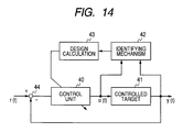
- the technique in Non-Japanese Patent Laid-open No. 2005-168166 is a control system that causes an output signal y (t) to converge to a target signal r (t); a method of least squares is applied to time-series data of an input signal u (t) supplied to a controlled target 41 and the output signal y (t) from the controlled target 41 to have an identifying mechanism 42 identify transmission functions in a plant (see FIG. 14 ).
- the technique in Japanese Patent Laid-open No. Hei 7(1995)-152429 can identify both rigid-body characteristics and resonant characteristics in a machine system. Since white noise needs to be applied, however, usage conditions are limited to offline adjustment.
- the third conventional technique has the advantage that transmission functions of a controlled target can be identified online, but when an ordinary recursive least square method is selected as the identifying algorithm, the amount of calculation is proportional to the square of the number of parameters (see Non-Japanese Patent Laid-open No. Hei 7(1995)-152429 , Yoji liguni, "Adaptive signal processing algorithm", Baifukan, 2000, Chapter 4 ). For this reason, an identifying unit must be mounted in a computing machine having a sufficient calculation capacity.
- control parameters can be automatically set in a position control unit, a speed control unit, and the like, and damping control parameters described in Japanese Patent Laid-open No. 2004-187432 can be automatically set with high precision, enabling high-performance control to be performed easier.
- An object of the present invention is to provide a motor controller and motor control system that can identify both rigid-body characteristics and resonant characteristics of a controlled target in an online state with a small amount of calculation.
- the motor control system has a motor connected to a load through a connecting shaft, an electric power converter for driving the motor, and a motor controller for controlling the electric power converter according to a target command value and a motor current that flows in the motor;
- the motor controller has an auto tuner that receives a motor torque value and detected motor rotational speed value of the motor as input signals and automatically adjusts control parameters used in the control;
- the auto tuner handles a machine system including the motor, connecting shaft, and load as a rigid-body model and a resonant model that are connected in series, the auto tuner having a parameter identifying means for separately identifying parameters set in the rigid-body model and parameters set in the resonant model.
- both rigid-body characteristics and resonant characteristics of a controlled target can be identified online with a small amount of calculation.
- FIG. 1 A machine system used as a controlled target in embodiments described below will be described with reference to FIG. 1 .
- a motor 1 and a load 2 are interconnected through a connecting shaft 3.
- the controlled machine system is assumed to comprise two inertial models. That is, it is assumed that the motor 1 has a motor shaft represented by a vane wheel with a viscous friction coefficient D M and a rotor with a motor moment J M , the load 2 is, for example, a circular plate with a load moment J L of inertia, and the connecting shaft 3 is a spring or dumper with a viscous friction coefficient C F and a spring constant K F .
- the motor 1 is assumed to rotate at a motor torque of ⁇ M and a motor rotational speed ⁇ M .
- the load 2 is assumed to receive a steady disturbance torque value d M , which is corrected so as to be handled for the motor, due to, for example, a gravity of mg applied to its circumference and thereby rotate at a load rotational speed ⁇ L .
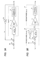
- the controlled machine system in FIG. 1 is handled as a rigid-body model and a resonant model that are connected in series, and parameters set in these two models are separately identified by a rigid-body model identifying part and a resonant model identifying part (see FIG. 5 ) so as to prevent the amount of calculation from being proportional to the square of the number of parameters to be identified.
- the rigid-body model identifying part first uses the motor torque ⁇ M and motor rotational speed ⁇ M to determine rigid-body parameters such as an estimated total moment of inertia J ⁇ , estimated viscous friction coefficient D M ⁇ , estimated steady disturbance torque value d M ⁇ by the method described in Japanese Patent Laid-open No. 2005-168166 or Non-Japanese Patent Laid-open No. 2005-168166 (Takashi Suzuki, "Adaptive control", Corona Publishing, 2001, Chapter 1).
- Rigid-body models parameters determined in advance are then set in the rigid-body model, and an estimated rigid-body rotational speed ⁇ RD ⁇ is calculated. Equation (1) is used for this calculation for the rigid-body model; s in the equation is a Laplace operator.
- ⁇ RD - ⁇ M - d M - / J - ⁇ s + D M -
- the resonant model identifying part identifies v resonant parameters, by which a resonant model is determined, by using a recursive least square method (see Non-Japanese Patent Laid-open No. 2005-168166 or Non-Japanese Patent Laid-open No. Hei 7(1995)-152429 ), according to an estimated rigid-body rotational speed value ⁇ RD ⁇ calculated from equation (1) and the motor rotational speed ⁇ M .
- variable ⁇ M is the value of torque generated in the motor
- variable ⁇ M is the motor rotational speed
- variable ⁇ S is the value of torque generated in the motor when the connecting shaft is twisted
- variable ⁇ d is the value of viscous friction torque exerted on the motor shaft
- s is a Laplace operator.
- ⁇ a is an anti-resonant angular frequency
- ⁇ a is an attenuation coefficient at an anti-resonant point
- ⁇ m is a resonant angular frequency
- ⁇ m is an attenuation coefficient at a resonant point
- the two-inertial model in FIG. 2 is equal to a case in which the steady disturbance torque value d M , which is corrected so as to be handled for the motor shaft, and the viscous friction torque value ⁇ d exerted on the motor shaft are subtracted from the motor generating torque ⁇ M , which is an input signal to the transmission function G MR (s) represented as in equation (2). Accordingly, the two-inertia model in FIG. 2 is equivalent to the model shown in FIG. 3A . The equivalent two-inertia model in FIG. 3A , obtained in this way, is represented simply, as compared with FIG.
- G MR (s) cannot be divided as it is.
- FIG. 3B an approximate two-inertia model shown in FIG. 3B is used instead of the model shown in FIG. 3A .
- the viscous friction torque value ⁇ d exerted on the motor shaft is replaced with an approximate viscous friction torque value ⁇ d ⁇ exerted on the motor shaft, which is calculated by equation (8).
- ⁇ d - D M ⁇ ⁇ RD
- the rigid-body rotational speed ⁇ R D used as an input signal is obtained from the input part of the resonant model 77 shown in FIG. 3B .
- the model can then be divided, ⁇ RD being a boundary.
- ⁇ RD has rigid-body characteristics with less vibrating components compared with the motor rotational speed ⁇ M .
- ⁇ RD will be referred to as the rigid-body rotational speed.
- a block that derives the rigid-body rotational speed from the input signal ⁇ M and steady disturbance torque value d M will be referred to as the rigid-body model, and another block that derives the motor rotational speed ⁇ M to which resonance characteristics are added from the rigid-body rotational speed ⁇ RD will be referred to as the resonant model.
- G RS (s) in the resonant model is represented as in equation (11).
- G RS s ( ⁇ m / ⁇ a ⁇ ) 2 ⁇ s 2 + 2 ⁇ ⁇ a ⁇ ⁇ a ⁇ s + ⁇ a 2 / s 2 + 2 ⁇ ⁇ m ⁇ ⁇ m ⁇ s + ⁇ m 2
- the transmission function G RS (s) in the resonant model has a minimum gain at the anti-resonant angular frequency ⁇ a when the gain in a low-frequency area is 1 and the gain in a high-frequency area is ( ⁇ m/ ⁇ a) 2 , and has a maximum gain at the resonant angular frequency ⁇ m. Since preparation as described above is completed, in FIG. 3A , the transmission function of the motor rotational speed ⁇ M corresponding to the motor generating torque ⁇ M is defined as G MB (s).
- the transmission function of the motor rotational speed ⁇ M corresponding to the motor generating torque ⁇ M is defined as G MA (s).
- G MA (s)/G MB (s) The ratio G MA (s)/G MB (s) between the two transmission functions will be obtained as described below.
- G MB (s) and G MA (s) are respectively represented as in equations (12) and (13).
- G MB s 1 / J M + J L ⁇ s ⁇ G RS / 1 + D M / J M + J L ⁇ s ⁇ G RS
- G MA s G RD s / G RS s
- G MA (s)/G MB (s) is determined from equations (9), (10), (12), and (13), as indicated by equation (14).
- G MA s / G MB s 1 + ⁇ rd / s ⁇ G RS s / 1 + ⁇ rd / s
- Equation (14) represents a ratio of the approximate two-inertia model G MA (s) shown in FIG. 3B to the equivalent two-inertia model G MB (s) shown in FIG. 3A .
- the ratio is preferably 1. That is, it suffices that the denominator and numerator in equation (14) preferably equal each other.
- the second term in the numerator additionally includes the resonant model characteristics G RS (s) described in equation (11), so it is apparent that the denominator does not equal the numerator. Since the low-frequency area gain of G RS (s) is 1 in the low-frequency area, however, the denominator nearly equals the numerator and the error is completely eliminated.
- the high-frequency gain of G RS (s) is ( ⁇ m/( ⁇ a) 2 . Since ( ⁇ rd/s) becomes small, however, both the denominator and numerator nearly equal 1. In this case as well, the error is completely eliminated.
- the last problem to solve is phenomena at the anti-resonant point and resonant point of the resonant model characteristics G RS (s).
- ( ⁇ rd/s) needs to be sufficiently small at the anti-resonant point and resonant point of the resonant model characteristics G RS (s).
- This requirement is satisfied when a breakpoint angular frequency ⁇ rd of the rigid-body model is sufficiently smaller than the anti-resonant angular frequency ⁇ a of G RS (s). That is, when ⁇ rd ⁇ ⁇ a, the approximate two-inertia model shown in FIG. 3B can be used.
- Equation (10) indicates that the requirement, ⁇ rd ⁇ ⁇ a, is satisfied when the viscous friction coefficient D M is small, so the requirement is satisfied when an ordinary motor is used.
- both the controlled rigid-body characteristics and resonant characteristics can be identified online.
- the control parameters to be set in the position control unit, the speed control unit, and the like are adjusted, the resonant characteristics can also be included in a consideration.
- the controlled machine system is handed as a rigid-body model and a resonant model that are connected in series, identification becomes possible with a smaller amount of calculation than in the prior art, contributing to expansion of the application range.
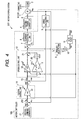
- the motor control system in an embodiment of the present invention will be described with reference to the block diagram in FIG. 4 .
- auto tuning processing is performed, by which an optimum speed control unit gain and position control unit gain can be set even in a normal unit operation state, according to the mechanical characteristics of a load that constantly changes with time. This embodiment will be described in detail below.
- the motor control system 200 in FIG. 4 includes a motor 1, a load 2 driven by the motor 1, a connecting shaft 3 for connecting the motor 1 to the load 2, an electric power converter 4 for driving the motor 1, a position detector 27 that is attached to the rotational axis of the motor 1 and outputs a detected position value ⁇ M of the rotational axis of the motor 1, a current detector 6 that detects a current that flows in the motor 1, and a motor controller 100.
- the motor controller 100 includes a speed calculating unit 5, a current control unit 8, a first-order lag filter 9, a torque constant amplifier 10, an auto tuner 11, a speed control unit 12, a position control unit 14, a position command generator 17, and subtracters, 7, 13, and 250.
- the motor controller 100 performs dq vector conversion on the motor current to obtain an exciting axis component and a torque axis component that is electrically orthogonal to the exciting axis. Only a detected value Iq of the torque axis current will be described below. A value Id of the exciting axis component is usually set to 0, so its description will be omitted.
- the speed calculating unit 5 calculates the motor rotational speed ⁇ M from a change in the detected position value ⁇ M with time.
- the current detector 6 obtains a detected torque current value Iq and supplies it to the motor 1.
- the subtracter 7 calculates a difference Ie in current between a torque current command value Iq* and the detected torque current value Iq supplied to the motor 1.
- the current control unit 8 performs pulse width control for the electric power converter 4 according to the change Ie in current.
- the first-order lag filter 9 receives the torque current command value Iq* and outputs an estimated torque current value Iq ⁇ ; its gain crossover angular frequency is set so that it equals the gain crossover angular frequency of a current control system in the current control unit 8.
- the torque constant amplifier 10 receives the estimated torque current value Iq ⁇ , calculates a motor torque value ⁇ M , and sets a value equal to a torque constant kt of the motor 1.
- the auto tuner 11 receives the motor torque value ⁇ M and time-series data of the motor rotational speed ⁇ M , and outputs an estimated total moment of inertia J ⁇ of the machine system comprising the motor 1, the connecting shaft 3, and the load 2, which is the target to drive, as well as an optimum gain crossover angular frequency ⁇ S of the speed control unit, and an optimum gain crossover angular frequency ⁇ p of the position control unit.
- the speed control unit 12 outputs the torque current command value Iq* according to a difference ⁇ e in motor rotational speed.
- the speed control unit 12 has a proportional integral control structure; the speed control unit 12 performs calculation represented as in equation (15), in which s is a Laplace operator.
- the estimated total moment of inertia J ⁇ and the gain crossover angular frequency ⁇ S in the speed control system, which are parameters set in a proportional amplifier 18 and integrating amplifier 19, are also updated at appropriate times by the auto tuner 11.
- Iq * J ⁇ s ⁇ + J ⁇ s ⁇ 2 / N N ⁇ s ⁇ ⁇ e
- the subtracter 13 calculates the difference ⁇ e in motor rotational speed between the motor rotational speed command value ⁇ M * and motor rotational speed ⁇ M .
- the position control unit 14 outputs the motor rotational speed command value ⁇ M * according to a difference ⁇ e in motor rotational position.
- the position control unit 14 has a proportional control structure; the position control unit 14 uses a variable amplifier 22 to multiply the motor rotational speed difference ⁇ e by the gain crossover angular frequency ⁇ p of the position control unit, and outputs the resulting value as the motor rotational speed command value ⁇ M *.
- the gain ⁇ p is updated at appropriate times by the auto tuner 11.
- the position command generator 17 generates a position control input command value ⁇ M *, which is a target command value.
- the subtracter 250 calculates the motor position difference ⁇ e between the position control input command value ⁇ M * and detected motor position value ⁇ M .
- the position command generator 17 may be disposed outside the motor controller 100.
- the structure of the auto tuner 11 will be described below in detail with reference to FIG. 5 .
- the auto tuner 11 in FIG. 5 includes low-pass filters (LPFs) 90 and 91, a rigid-body model identifying part 92, a rigid-body model 93, a resonant model 94, a resonant model identifying part 95, a discrete/continuous parameter converter 97, a control parameter adjusting part 98, and an adder 96.
- LPFs low-pass filters
- the LPFs 90 and 91 which are high-order low-pass filters, are used as anti-aliasing filters. Their cutoff frequencies are set to about half to one-third the sampling frequency of the auto tuner 11.
- the LPF 90 receives the motor torque value ⁇ M , and outputs a filtered motor torque value ⁇ MF ;
- the LPF 91 receives the motor rotational speed ⁇ M , and outputs a filtered motor rotational speed ⁇ MF .
- the rigid-body model identifying part 92 is structured by a known technique (see Japanese Patent Laid-open No. 2005-168166 and Non-Japanese Patent Laid-open No. 2005-168166 ) in which the motor torque value ⁇ M and motor rotational speed ⁇ M are used to output the estimated total moment of inertia J ⁇ , an estimated viscous friction coefficient D M ⁇ , and an estimated steady disturbance torque value d M ⁇ _f during the forward rotation or estimated steady disturbance torque value d M ⁇ _r during the reverse rotation.
- the rigid-body model 93 receives the filtered motor torque value ⁇ MF and outputs the estimated rigid-body rotational speed value ⁇ RD ⁇ by calculating equation (1) in real time.
- the identification results derived from the calculation by the rigid-body model identifying part 92 are used as the estimated total moment of inertia J ⁇ , estimated viscous friction coefficient D M ⁇ , and estimated steady disturbance torque value d M ⁇ , which are necessary for calculation in equation (1), making the estimated rigid-body rotational speed value ⁇ RD ⁇ highly accurate.
- the resonant model 94 receives the estimated rigid-body rotational speed value ⁇ RD ⁇ output by the rigid-body model 93 and the filtered motor rotational speed ⁇ MF , and outputs a filtered estimated motor rotational speed value ⁇ MF ⁇ .
- the calculation equation used by the resonant model 94 is basically the same as the transmission function G RS (s) as described in the explanation of FIG. 3B .
- G RS (s) For convenience in parameter identification in a discrete time zone, which will be described later, an equation for one-stage-ahead (one-sample-ahead) prediction will be used, the equation being derived from an equation obtained by making the transmission function G RS (s) discrete.
- the subtracter 96 calculates prediction error ⁇ (N) by subtracting ⁇ MF ⁇ from ⁇ MF .
- the resonant model identifying part 95 uses the estimated rigid-body rotational speed value ⁇ RD ⁇ and filtered motor rotational speed ⁇ MF , and outputs a previously estimated parameter vector value ⁇ (N - 1) necessary in the resonant model 94 to calculate the equation for one-stage-ahead (one-sample-ahead) prediction so that the prediction error ⁇ (N) output by the subtracter 96 by using the recursive least square method is minimized.
- the discrete/continuous parameter converter 97 converts the previously estimated parameter vector value ⁇ (N - 1) output by the resonant model identifying part 95 to a continuous parameter to calculate an estimated anti-resonant angular frequency value ⁇ a ⁇ and an estimated anti-resonant-point attenuation coefficient ⁇ a ⁇ as estimated values of the anti-resonant angular frequency value ⁇ a and anti-resonant-point attenuation coefficient ⁇ a in the resonant model transmission function G RS (s) indicated in equation (11).
- the control parameter adjusting part 98 uses the estimated anti-resonant angular frequency value ⁇ a ⁇ and estimated anti-resonant-point attenuation coefficient ⁇ a ⁇ output by the discrete/continuous parameter converter 97 to determine and output a speed control gain crossover angular frequency ⁇ s and position control gain crossover angular frequency ⁇ p.
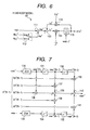
- the rigid-body model identifying part 92 in FIG. 6 includes subtracters 111 and 113, multipliers 114 and 116, an integrator 115, and a selector switch 112.
- the selector switch 112 selects a contact A when the motor rotates in the normal direction, and selects another contact B when the motor rotates in the reverse direction. Accordingly, an output signal d M ⁇ from the selector switch 112 is correctly set to the estimated steady disturbance torque value d M ⁇ _f during the forward rotation when the motor rotates in the normal direction or to the estimated steady disturbance torque value d M ⁇ _r during the reverse rotation when the motor rotates in the reverse direction.
- the subtracter 111 subtracts the estimated steady disturbance torque value d M ⁇ output by the selector switch 112 from the filtered motor torque value ⁇ MF to calculate an estimated motor torque value ⁇ MC ⁇ for which the steady disturbance torque value is considered.
- the subtracter 113 subtracts the estimated viscous friction torque value ⁇ d ⁇ exerted on the motor shaft, which is output by the multiplier 116, from the estimated motor torque value ⁇ MC ⁇ for which the steady disturbance torque value is considered, which is output by the subtractor 111, and outputs an estimated motor acceleration/deceleration ⁇ a ⁇ .
- the multiplier 114 multiplies the estimated motor acceleration/deceleration ⁇ a ⁇ output by the subtractor 113 by the reciprocal of the estimated total moment of inertia J ⁇ .
- the integrator 115 integrates the multiplication result produced by the multiplier 114 to obtain the estimated rigid-body rotational speed value ⁇ RD ⁇ . To eliminate an effect of stationary friction torque for which moldering is not performed, the integration is performed only when the motor acceleration and motor speed reach at least fixed values.
- An initial estimated rigid-body rotational speed value ⁇ RD ⁇ _0 which is an initial value at the start of the integration, is set to the filtered motor rotational speed ⁇ MF at the start of the integration.
- the multiplier 116 multiplies the estimated rigid-body rotational speed value ⁇ RD ⁇ output by the integrator 115 by the estimated viscous friction coefficient D M ⁇ and outputs the estimated viscous friction torque value ⁇ d ⁇ exerted on the motor shaft.
- the discrete transmission function G RS (z) corresponding to G RS (s) can be represented as in equation (16).
- Coefficients a1, a2, b0, b1, and b2 in equation (16) can also be represented as in equations (17) to (21).
- K in equations (19) to (21) is defined as in equation (22).
- K 1 - 2 ⁇ e - adT ⁇ cos b d ⁇ T + e - 2 ⁇ adT / 1 - 2 ⁇ e - anT ⁇ cos b n ⁇ T + e - 2 ⁇ anT
- Coefficients a n , b n , a d , and b d in equations (17), (18), and (20) to (22) can be represented as in equations (23) to (26) below by using parameters ⁇ a, ⁇ a, ⁇ m, and ⁇ m in the transmission function G RS (s) of the resonant model in the continuous area.
- the continuous transmission function G RS (s) can be converted to its corresponding discrete transmission function G RS (z) by using the above relational equations (16) to (26). Conversely, it is also possible to calculate parameters ⁇ a, ⁇ a, ⁇ m, and ⁇ m in G RS (s) from the coefficients b0, b1, b2, a1, and a2 in G RS (z).
- the resonant model 94 is structured so as to calculate the filtered estimated motor rotational speed value ⁇ MF ⁇ according to equation (16), if the resonant model identifying part 95 adjusts the above coefficients b0, b1, b2, a1, and a2 so that the prediction error ⁇ (N) between the filtered estimated motor rotational speed value ⁇ MF ⁇ and the filtered motor rotational speed ⁇ MF is minimized, resonant model identification can be implemented.
- the equation to calculate the filtered estimated motor rotational speed value ⁇ MF ⁇ in the resonant model 94 will be described below.
- the transmission function to be identified is represented as in equation (16). Since the input signal to the transmission function is the estimated rigid-body rotational speed value ⁇ RD ⁇ and the output signal from the transmission function is the filtered motor rotational speed ⁇ MF , equation (27) holds.
- ⁇ MF / ⁇ RD b 0 + b 1 ⁇ z - 1 + b 2 ⁇ z - 2 / ( 1 + a 1 ⁇ z - 1 + a 2 ⁇ z - 2 )
- Equation (27) can be rewritten as in equation (28).
- ⁇ MF a 1 ⁇ ⁇ MF ⁇ z - 1 - a 2 ⁇ ⁇ MF ⁇ z - 2 + b 0 ⁇ ⁇ RD ⁇ + b 1 ⁇ ⁇ RD ⁇ ⁇ z - 1 + b 2 ⁇ ⁇ RD ⁇ z - 2
- equation (28) is a relational equation that calculates the current filtered motor rotational speed ⁇ MF from the previous and current estimated rigid-body rotational speed values ⁇ RD ⁇ and the previous filtered motor rotational speed ⁇ MF ⁇
- equation (28) When the coefficients b0, b1, b2, a1, and a2 in equation (28) are replaced with the estimated values one sample before rather than true values, equation (29) holds.
- ⁇ ⁇ MF ⁇ ⁇ ⁇ N - 1 ⁇ T ⁇ N
- ⁇ ⁇ N - 1 [ a 1 ⁇ ⁇ N - 1 , a 2 ⁇ ⁇ N - 1 , b 0 ⁇ ⁇ N - 1 , b 1 ⁇ ⁇ N - 1 , b 2 ⁇ ⁇ N - 1 ⁇ ] T
- the elements of data vector ⁇ (N) are ⁇ MF (N - 1) indicating ⁇ MF one sample before, ⁇ MF (N - 2) indicating ⁇ MF two samples before, ⁇ RD ⁇ (N) indicating current ⁇ RD ⁇ , ⁇ RD ⁇ (N - 1) indicating ⁇ RD ⁇ one sample before, and ⁇ RD ⁇ (N - 2) indicating ⁇ RD ⁇ two samples before.
- ⁇ ( N ) [ - ⁇ MF ⁇ N - 1 , - ⁇ MF ⁇ N - 2 , ⁇ RD ⁇ N , ⁇ RD ⁇ ⁇ N - 1 , ⁇ RD ⁇ ⁇ N - 2 ⁇ ] T
- ⁇ MF ⁇ in equation (29) is the current filtered estimated motor rotational speed value; since it is distinguished from the filtered motor rotational speed ⁇ MF , it is clear that the coefficients b0, b1, b2, a1, and a2 have been replaced with the estimated values one sample before rather than true values.
- FIG. 7 is a structural diagram that concretizes equation (29).
- the structure receives estimated rigid-body rotational speed value ⁇ RD ⁇ , estimated values of the b0, b1, b2, a1, and a2 one sample before, which are elements of the previously estimated parameter vector value ⁇ (N - 1), and filtered estimated motor rotational speed value ⁇ MF ⁇ , and uses these received values to calculate the filtered estimated motor rotational speed value ⁇ MF ⁇ .
- the resonant model identifying part 95 shown in FIG. 5 will be described next in detail.
- a basic operation of the resonant model identifying part 95 is to update the estimated parameter vector value ⁇ (N) at intervals of the sample cycle T by using the recursive least square method (see Non-Japanese Patent Laid-open No. Hei 7(1995)-152429 ).
- Equation (32) is used for update calculation. To perform this update, a value obtained by multiplying the gain vector k (N) by the prediction error ⁇ (N) is added to the previously estimated parameter vector value ⁇ (N - 1), the initial value of which is 0.
- the gain vector k (N) used in equation (32) is obtained from a matrix operation according to equation (33).
- a matrix P (N - 1) indicates the previous value of a covariance matrix P (N) comprising five rows by five columns, and ⁇ is forgetting coefficient, which is greater than 0 and equal to or smaller than 1.
- the matrix P (N) is updated by equation (34).
- a value obtained by multiplying a unit matrix comprising five rows by five columns by a sufficient large positive constant is used as an initial value P (-1) of the matrix P (N).
- FIG. 8 is a structural diagram that concretizes equations (32), (33), and (34) described above.
- the structure includes a data vector generating part 150, a covariance matrix calculating part 151, a memory 152, a gain vector calculating part 153, a multiplier 154, an adder 155, and a one-sample time delay element 156.
- the data vector generating part 150 generates the vector elements in equation (31) from the estimated rigid-body rotational speed value ⁇ RD ⁇ and the filtered motor rotational speed ⁇ MF , and outputs the generated vector elements as the data vector ⁇ (N).
- the covariance matrix calculating part 151 uses the forgetting coefficient ⁇ , data vector ⁇ (N), and gain vector k (N) to calculate the covariance matrix P (N) according to equation (34), and outputs its previous value P (N - 1).
- the memory 152 stores the forgetting coefficient ⁇ , which is greater than 0 and equal to or smaller than 1.
- the gain vector calculating part 153 uses the forgetting coefficient ⁇ , previous covariance matrix value P (N - 1), and data vector ⁇ (N) to calculate the gain vector k (N) according to equation (33), and outputs the calculation result.
- the multiplier 154 multiplies the gain vector k (N) output by the gain vector calculating part 153 by the prediction error ⁇ (N).
- the adder 155 adds the output result from the multiplier 154 to the previously estimated parameter vector value ⁇ (N - 1).
- the one-sample time delay element 156 receives the estimated parameter vector value ⁇ (N) and outputs the previously estimated parameter vector value ⁇ (N - 1).
- the discrete/continuous parameter converter 97 receives the previously estimated parameter vector value ⁇ (N - 1) to calculate the machine-system estimated anti-resonant angular frequency value ⁇ a ⁇ and machine-system estimated anti-resonant-point attenuation coefficient ⁇ a ⁇ according to equations (35) and (36), and outputs the calculated values.
- ⁇ a ⁇ ⁇ a n ⁇ 2 + b n ⁇ 2
- a n ⁇ and b n ⁇ are each the sampling cycle T. They are calculated according to equations (37) and (38).
- a n ⁇ - 1 / 2 ⁇ T ⁇ 1 ⁇ n ⁇ b 2 ⁇ ⁇ N - 1 / b 0 ⁇ ⁇ N - 1
- b n ⁇ 1 / T ⁇ arccos [ - b 1 ⁇ ⁇ N - 1 / 2 ⁇ ⁇ b 0 ⁇ ⁇ N - 1 ⁇ b 2 ⁇ ⁇ N - 1
- control parameter adjusting part 98 performs adjustment particularly based on the machine-system estimated anti-resonant angular frequency value ⁇ a ⁇ . For example, the control parameter adjusting part 98 sets the speed control gain crossover angular frequency ⁇ s to ⁇ a ⁇ multiplied by 2 and also sets the position control gain crossover angular frequency ⁇ P to ⁇ a ⁇ divided by 3.5.
- the motor controller 100 sets initial values of the parameters in the speed control unit and position control unit (S191). For example, the motor controller 100 sets N N to 10, ⁇ s to 2 ⁇ ⁇ 30 Hz, ⁇ P to ⁇ S /7, and J ⁇ to the moment of inertia of the motor alone.
- the motor controller 100 then identifies only the rigid-body model parameters online to obtain the estimated total moment of inertia J ⁇ , the estimated viscous friction coefficient D M ⁇ , the estimated steady disturbance torque value d M ⁇ _f during the forward rotation, and the estimated steady disturbance torque value d M ⁇ _r during the reverse rotation (S192). Next, the motor controller 100 sets the estimated total moment of inertia J ⁇ in the speed control unit (S193).
- the motor controller 100 calculates acceleration ⁇ MF from the filtered motor rotational speed ⁇ MF , and determines whether the absolute value of ⁇ MF is equal to or greater than a prescribed value ⁇ A (S 194). If the absolute value is less than the prescribed value ⁇ A (producing a No result in S194), the motor controller 100 repeats the decision process S194. If the absolute value is equal to or greater than the prescribed value ⁇ A (producing a Yes result in S194), the motor controller 100 proceeds to decision process S 195.
- decision process S 195 the motor controller 100 determines whether the absolute value of the filtered motor rotational speed ⁇ MF is equal to or greater than a prescribed value ⁇ A (S195). If the absolute value is less than the prescribed value ⁇ A (producing a No result in S195), the motor controller 100 returns to the decision process S194. If a Yes result is produced in the decision process S195, the motor controller 100 proceeds to decision process S 196.
- decision process S 196 the motor controller 100 determines the direction of rotation from the sign of the filtered motor rotational speed ⁇ MF . If ⁇ MF is greater than 0 (producing a Yes result in decision process S 196), the motor controller 100 proceeds to process S 197, where the motor controller 100 sets the estimated steady disturbance torque value d M ⁇ _f during the forward rotation as the estimated steady disturbance torque value d M ⁇ and then proceeds to process S199. If ⁇ MF is not greater than 0 (producing a No result in S 196), the motor controller 100 proceeds to process S 198, where the motor controller 100 sets the estimated steady disturbance torque value d M ⁇ _r during the reverse rotation as the estimated steady disturbance torque value d M ⁇ , and then proceeds to process S 199.
- the motor controller 100 sets the estimated total moment of inertia J ⁇ , estimated viscous friction coefficient D M ⁇ , estimated steady disturbance torque value d M ⁇ in the rigid-body model 93 (see FIG. 5 ), and proceeds to process S200.
- the motor controller 100 sets the current filtered motor rotational speed ⁇ MF as the initial estimated rigid-body rotational speed value ⁇ RD ⁇ _0 to be given to the rigid-body model 93, and proceeds to process 5201.
- process S201 the motor controller 100 starts rigid-body model calculation, and then proceeds to process S202 immediately.
- process S202 the motor controller 100 starts resonant model parameter identification and proceeds to decision process S203.
- decision process S203 the motor controller 100 determines the absolute value of the acceleration ⁇ MF calculated from the filtered motor rotational speed ⁇ MF . If the absolute value of ⁇ MF is smaller than a prescribed value ⁇ I (producing a Yes result), the motor controller 100 proceeds to process S204, where the motor controller 100 terminates the resonant model parameter identification.
- the motor controller 100 proceeds to decision process S205, where the motor controller 100 determines the absolute value of the filtered motor rotational speed ⁇ MF . If the absolute value of ⁇ MF is smaller than a prescribed value ⁇ I in decision process S205, the motor controller 100 proceeds process S204, where the motor controller 100 terminates the resonant model parameter identification.
- the motor controller 100 If the absolute value of ⁇ MF is equal to or greater than the prescribed value ⁇ I (producing a No result in process S205), the motor controller 100 returns to decision process S203. Upon the completion of the resonant model parameter identification in process S204, the motor controller 100 moves to process S206, where the motor controller 100 performs conversion calculation in the discrete/continuous parameter converter 97 (see FIG. 5 ) so as to convert the previously estimated parameter vector value ⁇ (N - 1) to continuous parameters, that is, the machine-system estimated anti-resonant angular frequency value ⁇ a ⁇ and machine-system estimated anti-resonant-point attenuation coefficient ⁇ a ⁇ , and proceeds to process S207.
- the motor controller 100 sets the speed control gain crossover angular frequency ⁇ s to ⁇ a ⁇ multiplied by 2 and also sets the position control gain crossover angular frequency ⁇ p to ⁇ a ⁇ divided by 3.5. Then motor controller 100 sets the gain for the speed and position control unit (S207). This completes the parameter adjustment.
- the motor torque value ⁇ M input to the auto tuner 11 has been calculated from the q-axis current command value Iq*, but it can also be calculated from the detected torque current value Iq.
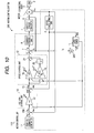
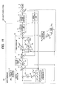
- the motor control system 210 in a second embodiment, shown in FIG. 10 includes a motor controller 110; in the motor controller 110, an amplifier 240 multiplies the detected torque current value Iq by a value equivalent to the torque constant of the motor 1 to calculate the motor torque value ⁇ M .
- the motor controller 120 in the third embodiment differs from the first embodiment in that a damping control unit 16 is provided among the position command generator 17, the position control unit 14, a subtracter 15, that is, the damping control unit 16 and subtracter 15 are provided between the position command generator 17 and position control unit 14.
- the subtracter 24 subtracts the estimated load position value ⁇ L ⁇ from a dumping control input command value ⁇ M ** output from the position command generator 17 and calculates an estimated axis twist value.
- a dumping control amplifier 25 amplifies the estimated axis twist value calculated by the subtracter 24 by k1, which is equal to or greater than 0 and less than 1, and outputs the multiplication result.
- the subtracter 26 subtracts the output from the amplifier 25 from the dumping control input command value ⁇ M ** and outputs a position command in which the axis twist is alleviated as a position control input command ⁇ M *.
- An advantage in this embodiment in the operation of the damping control unit 16 is that the auto tuner 11 sets the machine-system estimated anti-resonant angular frequency value wa ⁇ and machine-system estimated anti-resonant-point attenuation coefficient ⁇ a ⁇ , which are required for calculation according to equation (39). Damping control can thereby be achieved with high accuracy, without adjustment being involved.
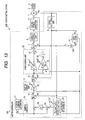
- Parameter identification by the auto tuner 11 in the third embodiment is the same as in the first embodiment, so its explanation will be omitted and only the entire sequence in parameter adjustment will be described below with reference to FIG. 12 .
- the motor controller 120 starts parameter identification in S390.
- the motor controller 120 then sets initial parameter values in the speed control unit 12 and position control unit 14 and disables damping control (S391). Specifically, the motor controller 120 sets N N to 10, ⁇ s to 2 ⁇ ⁇ 30 Hz, ⁇ P to ⁇ S /7, and J ⁇ to the moment of inertia of the motor alone, and also sets k1 to 0 so as to disable damping control.
- the motor controller 120 then identifies only the rigid-body model parameters online in process S392 to obtain the estimated total moment of inertia J ⁇ , the estimated viscous friction coefficient D M ⁇ , the estimated steady disturbance torque value d M ⁇ _ f during the forward rotation, and the estimated steady disturbance torque value d M ⁇ _ r during the reverse rotation.
- the motor controller 120 sets the estimated total moment of inertia J ⁇ in the speed control unit in process S393, and proceeds to decision process S394.
- decision process S394 the motor controller 120 calculates acceleration ⁇ MF from the filtered motor rotational speed ⁇ MF , and determines whether the absolute value of ⁇ MF is equal to or greater than the prescribed value ⁇ A. If a Yes result is produced in decision process S394, the motor controller 120 proceeds to decision process S395, where the motor controller 120 determines whether the absolute value of the filtered motor rotational speed ⁇ MF is equal to or greater than the prescribed value ⁇ A . If the absolute value is less than the prescribed value ⁇ A (producing a No result in S395), the motor controller 120 repeats decision process S394.
- the motor controller 120 moves to decision process S396.
- decision process S396 the motor controller 120 determines the direction of rotation from the sign of the filtered motor rotational speed ⁇ MF . If ⁇ MF is greater than 0 (producing a Yes result in decision process S396), the motor controller 120 proceeds to process S397, where the motor controller 120 sets the estimated steady disturbance torque value d M ⁇ _f during the forward rotation as the estimated steady disturbance torque value d M ⁇ , and then proceeds to process S399.
- the motor controller 120 proceeds to process S398, where the motor controller 120 sets the estimated steady disturbance torque value d M ⁇ _r during the reverse rotation as the estimated steady disturbance torque value d M ⁇ , and then proceeds to process S399.
- the motor controller 120 sets the estimated total moment of inertia J ⁇ , estimated viscous friction coefficient D M ⁇ , and estimated steady disturbance torque value d M ⁇ in the rigid-body model 93 (see FIG. 5 ).
- the motor controller 120 sets the current filtered motor rotational speed ⁇ MF as the initial estimated rigid-body rotational speed value ⁇ RD ⁇ _0 to be given to the rigid-body model 93.
- the motor controller 120 starts rigid-body model calculation, and then proceeds to process S402 immediately, where the 120 starts resonant model parameter identification.
- the motor controller 120 determines the absolute value of the acceleration ⁇ MF calculated from the filtered motor rotational speed ⁇ MF . If the absolute value of ⁇ MF is smaller than the prescribed value ⁇ I (producing a Yes result in S403), the motor controller 120 proceeds to process S404, where the motor controller 120 terminates the resonant model parameter identification. If the absolute value of ⁇ MF is equal to greater than the prescribed value ⁇ I (producing a No result in decision process S403), the motor controller 120 proceeds to decision process S405, where the motor controller 120 determines the absolute value of the filtered motor rotational speed ⁇ MF .
- the motor controller 120 proceeds process S404, where the motor controller 120 terminates the resonant model parameter identification. If the absolute value of ⁇ MF is equal to or greater than the prescribed value ⁇ I (producing a No result in decision process S405), the motor controller 120 returns to decision process S403.
- the motor controller 120 Upon the completion of the resonant model parameter identification in process S404, the motor controller 120 proceeds to process S406, where the motor controller 120 performs conversion calculation in the discrete/continuous parameter converter 97 (see FIG. 5 ) so as to convert the previously estimated parameter vector value ⁇ (N - 1) to the machine-system estimated anti-resonant angular frequency value ⁇ a ⁇ and machine-system estimated anti-resonant-point attenuation coefficient ⁇ a ⁇ .
- the motor controller 120 sets the speed control gain crossover angular frequency ⁇ S to ⁇ a ⁇ multiplied by 2 and also sets the position control gain crossover angular frequency ⁇ p to ⁇ a ⁇ divided by 3.5.
- the motor controller 120 proceeds to process S408, where the motor controller 120 sets the machine-system estimated anti-resonant angular frequency value ⁇ a ⁇ and machine-system estimated anti-resonant-point attenuation coefficient ⁇ a ⁇ in the load position estimating unit 23 in the damping control unit 16 (see FIG. 11 ) and then sets the damping control amplifier k1 to, for example, 0.5 to enable damping control. This completes the parameter adjustment.
- the fourth embodiment differs from the third embodiment in that the motor torque value ⁇ M used in the auto tuner 11 is calculated by a different method. Specifically, although the motor torque value ⁇ M has been derived from the torque current command value Iq* in the third embodiment, a motor controller 130 in the fourth embodiment has an amplifier 240 multiply the detected torque current value Iq by a value equivalent to the torque constant of the motor 1 to calculate the motor torque value ⁇ M .
- a position control unit is provided in front of the proportional amplifier 18 so as to perform position control, speed control can be performed without having to use a position control unit.
- the motor rotational speed command value ⁇ M * is used as the target command value.
Landscapes
- Engineering & Computer Science (AREA)
- Robotics (AREA)
- Mechanical Engineering (AREA)
- Human Computer Interaction (AREA)
- Manufacturing & Machinery (AREA)
- Physics & Mathematics (AREA)
- General Physics & Mathematics (AREA)
- Automation & Control Theory (AREA)
- Power Engineering (AREA)
- Control Of Electric Motors In General (AREA)
- Control Of Ac Motors In General (AREA)
Applications Claiming Priority (1)
| Application Number | Priority Date | Filing Date | Title |
|---|---|---|---|
| JP2007058275A JP4340299B2 (ja) | 2007-03-08 | 2007-03-08 | モータ制御装置、及びモータ制御システム |
Publications (3)
| Publication Number | Publication Date |
|---|---|
| EP1968184A2 true EP1968184A2 (fr) | 2008-09-10 |
| EP1968184A3 EP1968184A3 (fr) | 2009-11-25 |
| EP1968184B1 EP1968184B1 (fr) | 2012-01-04 |
Family
ID=39580888
Family Applications (1)
| Application Number | Title | Priority Date | Filing Date |
|---|---|---|---|
| EP08001435A Active EP1968184B1 (fr) | 2007-03-08 | 2008-01-25 | Contrôleur de moteur et système de contrôle de moteur |
Country Status (3)
| Country | Link |
|---|---|
| EP (1) | EP1968184B1 (fr) |
| JP (1) | JP4340299B2 (fr) |
| CN (1) | CN101262199B (fr) |
Cited By (14)
| Publication number | Priority date | Publication date | Assignee | Title |
|---|---|---|---|---|
| EP2241946A1 (fr) | 2009-04-15 | 2010-10-20 | FESTO AG & Co. KG | Procédé de détermination de paramètres de réglage d'un dispositif de réglage destiné au réglage de l'entraînement d'un système d'entraînement |
| EP2362287A3 (fr) * | 2010-02-23 | 2012-04-04 | Sanyo Denki Co., Ltd. | Procédé et système de commande de moteur |
| US8232758B2 (en) | 2009-08-28 | 2012-07-31 | Fanuc Ltd | Controller of electric motor having function of estimating inertia and friction simultaneously |
| US20130026963A1 (en) * | 2011-07-27 | 2013-01-31 | Fanuc Corporation | Electric motor controller comprising function for simultaneously estimating inertia, friction, and spring |
| EP2818947A1 (fr) * | 2013-06-25 | 2014-12-31 | Linestream Technologies | Procédé de réglage automatique de largeur de bande de contrôleur |
| CN105471345A (zh) * | 2015-11-23 | 2016-04-06 | 广东工业大学 | 基于最大李雅普诺夫指数的无刷双馈电机混沌分析方法 |
| JP2016082705A (ja) * | 2014-10-16 | 2016-05-16 | 三菱重工業株式会社 | パラメータ同定装置、モータ制御システム、パラメータ同定方法及びプログラム |
| US9416652B2 (en) | 2013-08-08 | 2016-08-16 | Vetco Gray Inc. | Sensing magnetized portions of a wellhead system to monitor fatigue loading |
| EP2571159A3 (fr) * | 2011-09-01 | 2017-11-15 | Kabushiki Kaisha Yaskawa Denki | Appareil de commande de moteur |
| CN109842335A (zh) * | 2017-11-24 | 2019-06-04 | 宝时得科技(中国)有限公司 | 电动设备及电机控制装置 |
| CN111300406A (zh) * | 2020-01-17 | 2020-06-19 | 浙江理工大学 | 基于运动学分析的工业机器人轨迹精度补偿系统和方法 |
| CN112476423A (zh) * | 2020-11-12 | 2021-03-12 | 腾讯科技(深圳)有限公司 | 机器人的关节电机控制方法、装置、设备及存储介质 |
| CN116277034A (zh) * | 2023-05-15 | 2023-06-23 | 北京壹点灵动科技有限公司 | 应对负载变化的机器人控制方法、装置及电子设备 |
| KR20240100247A (ko) * | 2022-12-22 | 2024-07-01 | 가부시키가이샤 야스카와덴키 | 모터 제어 시스템, 제어 파라미터를 자동으로 조정하는 방법 및 비일시적 메모리 장치 |
Families Citing this family (18)
| Publication number | Priority date | Publication date | Assignee | Title |
|---|---|---|---|---|
| CN101727522B (zh) * | 2009-12-11 | 2012-08-01 | 中国电力科学研究院 | 一种基于出厂数据的电动机机电暂态仿真模型参数获取方法 |
| CN101783642A (zh) * | 2010-03-12 | 2010-07-21 | 华北电力大学 | 双馈型风力发电控制系统参数优化设计方法 |
| JP4983970B2 (ja) * | 2010-09-16 | 2012-07-25 | セイコーエプソン株式会社 | モーター制御装置 |
| JP5801143B2 (ja) * | 2011-08-29 | 2015-10-28 | 日本電産サンキョー株式会社 | モータシステムおよびモータ制御装置 |
| AT512002B1 (de) * | 2011-09-15 | 2014-02-15 | Xylem Ip Holdings Llc | Motorregelung für einen synchronmotor |
| CN104152625B (zh) * | 2014-08-27 | 2016-06-01 | 中冶南方工程技术有限公司 | 一种氧枪减速停车控制方法及装置 |
| JP2017207792A (ja) * | 2014-09-19 | 2017-11-24 | 株式会社日立産機システム | 複数のパラメータを同定する方法および複数のパラメータを同定する方法を用いた複数のパラメータ同定装置 |
| JP5935853B2 (ja) * | 2014-09-30 | 2016-06-15 | 株式会社明電舎 | ダイナモメータシステムの制御装置 |
| JP5980890B2 (ja) * | 2014-12-10 | 2016-08-31 | ファナック株式会社 | 実験モード解析を用いたフィルタ自動調整機能を有するサーボ制御装置 |
| EP3144754A1 (fr) | 2015-09-17 | 2017-03-22 | Siemens Aktiengesellschaft | Amortissement des oscillations de charge sans moyen de mesure supplementaire cote charge |
| JP6412071B2 (ja) * | 2016-08-22 | 2018-10-24 | ファナック株式会社 | モータ制御装置、モータ制御方法及びモータ制御用プログラム |
| WO2019188154A1 (fr) * | 2018-03-30 | 2019-10-03 | パナソニックIpマネジメント株式会社 | Dispositif d'entraînement de moteur |
| KR102060250B1 (ko) * | 2018-07-20 | 2019-12-27 | 현대위아 주식회사 | 원격제어 사격장치의 무장반동 감소 장치 및 방법 |
| WO2020075344A1 (fr) * | 2018-10-09 | 2020-04-16 | 株式会社日立産機システム | Procédé de commande à rétroaction et dispositif de commande à rétroaction |
| JP6925313B2 (ja) * | 2018-11-22 | 2021-08-25 | 株式会社日立産機システム | 電力変換装置 |
| CN109586633B (zh) * | 2018-11-30 | 2020-09-18 | 北京精密机电控制设备研究所 | 机电静压伺服系统的舵速和位置精确控制方法 |
| JP7178327B2 (ja) * | 2019-06-14 | 2022-11-25 | 株式会社日立産機システム | ノッチフィルタ調整装置、およびそれを備えたモータ制御装置 |
| JP7586782B2 (ja) * | 2021-06-29 | 2024-11-19 | 株式会社日立産機システム | モータ制御装置 |
Citations (3)
| Publication number | Priority date | Publication date | Assignee | Title |
|---|---|---|---|---|
| JPH07152429A (ja) | 1993-11-29 | 1995-06-16 | Mitsubishi Heavy Ind Ltd | パラメータ同定装置 |
| JP2004187432A (ja) | 2002-12-05 | 2004-07-02 | Hitachi Ltd | 電動機の位置制御装置 |
| JP2005168166A (ja) | 2003-12-02 | 2005-06-23 | Matsushita Electric Ind Co Ltd | 負荷特性演算装置及びモータ制御装置 |
Family Cites Families (2)
| Publication number | Priority date | Publication date | Assignee | Title |
|---|---|---|---|---|
| CN1157845C (zh) * | 2001-11-28 | 2004-07-14 | 艾默生网络能源有限公司 | 异步电机参数辨识方法 |
| KR20040093160A (ko) * | 2002-03-20 | 2004-11-04 | 가부시키가이샤 야스카와덴키 | 제어 정수 조정 장치 |
-
2007
- 2007-03-08 JP JP2007058275A patent/JP4340299B2/ja active Active
-
2008
- 2008-01-24 CN CN2008100038465A patent/CN101262199B/zh active Active
- 2008-01-25 EP EP08001435A patent/EP1968184B1/fr active Active
Patent Citations (3)
| Publication number | Priority date | Publication date | Assignee | Title |
|---|---|---|---|---|
| JPH07152429A (ja) | 1993-11-29 | 1995-06-16 | Mitsubishi Heavy Ind Ltd | パラメータ同定装置 |
| JP2004187432A (ja) | 2002-12-05 | 2004-07-02 | Hitachi Ltd | 電動機の位置制御装置 |
| JP2005168166A (ja) | 2003-12-02 | 2005-06-23 | Matsushita Electric Ind Co Ltd | 負荷特性演算装置及びモータ制御装置 |
Non-Patent Citations (2)
| Title |
|---|
| TAKASHI SUZUKI: "Adaptive control", 2001, CORONA PUBLISHING |
| YOJI IIGUNI: "Adaptive signal processing algorithm", 2000 |
Cited By (17)
| Publication number | Priority date | Publication date | Assignee | Title |
|---|---|---|---|---|
| EP2241946A1 (fr) | 2009-04-15 | 2010-10-20 | FESTO AG & Co. KG | Procédé de détermination de paramètres de réglage d'un dispositif de réglage destiné au réglage de l'entraînement d'un système d'entraînement |
| US8232758B2 (en) | 2009-08-28 | 2012-07-31 | Fanuc Ltd | Controller of electric motor having function of estimating inertia and friction simultaneously |
| EP2362287A3 (fr) * | 2010-02-23 | 2012-04-04 | Sanyo Denki Co., Ltd. | Procédé et système de commande de moteur |
| US20130026963A1 (en) * | 2011-07-27 | 2013-01-31 | Fanuc Corporation | Electric motor controller comprising function for simultaneously estimating inertia, friction, and spring |
| US8872463B2 (en) * | 2011-07-27 | 2014-10-28 | Fanuc Corporation | Electric motor controller comprising function for simultaneously estimating inertia, friction, and spring |
| EP2571159A3 (fr) * | 2011-09-01 | 2017-11-15 | Kabushiki Kaisha Yaskawa Denki | Appareil de commande de moteur |
| EP2818947A1 (fr) * | 2013-06-25 | 2014-12-31 | Linestream Technologies | Procédé de réglage automatique de largeur de bande de contrôleur |
| US9690261B2 (en) | 2013-06-25 | 2017-06-27 | Linestream Technologies | Method for automatically setting responsiveness parameters for motion control systems |
| US9416652B2 (en) | 2013-08-08 | 2016-08-16 | Vetco Gray Inc. | Sensing magnetized portions of a wellhead system to monitor fatigue loading |
| JP2016082705A (ja) * | 2014-10-16 | 2016-05-16 | 三菱重工業株式会社 | パラメータ同定装置、モータ制御システム、パラメータ同定方法及びプログラム |
| CN105471345A (zh) * | 2015-11-23 | 2016-04-06 | 广东工业大学 | 基于最大李雅普诺夫指数的无刷双馈电机混沌分析方法 |
| CN109842335A (zh) * | 2017-11-24 | 2019-06-04 | 宝时得科技(中国)有限公司 | 电动设备及电机控制装置 |
| CN111300406A (zh) * | 2020-01-17 | 2020-06-19 | 浙江理工大学 | 基于运动学分析的工业机器人轨迹精度补偿系统和方法 |
| CN112476423A (zh) * | 2020-11-12 | 2021-03-12 | 腾讯科技(深圳)有限公司 | 机器人的关节电机控制方法、装置、设备及存储介质 |
| KR20240100247A (ko) * | 2022-12-22 | 2024-07-01 | 가부시키가이샤 야스카와덴키 | 모터 제어 시스템, 제어 파라미터를 자동으로 조정하는 방법 및 비일시적 메모리 장치 |
| CN116277034A (zh) * | 2023-05-15 | 2023-06-23 | 北京壹点灵动科技有限公司 | 应对负载变化的机器人控制方法、装置及电子设备 |
| CN116277034B (zh) * | 2023-05-15 | 2023-09-12 | 北京壹点灵动科技有限公司 | 应对负载变化的机器人控制方法、装置及电子设备 |
Also Published As
| Publication number | Publication date |
|---|---|
| CN101262199B (zh) | 2012-06-20 |
| EP1968184B1 (fr) | 2012-01-04 |
| EP1968184A3 (fr) | 2009-11-25 |
| JP4340299B2 (ja) | 2009-10-07 |
| CN101262199A (zh) | 2008-09-10 |
| JP2008228360A (ja) | 2008-09-25 |
Similar Documents
| Publication | Publication Date | Title |
|---|---|---|
| EP1968184B1 (fr) | Contrôleur de moteur et système de contrôle de moteur | |
| EP2571159B1 (fr) | Appareil de commande de moteur | |
| CN113602101B (zh) | 一种用于抑制电机抖动的控制方法、装置及车辆 | |
| US10752286B2 (en) | Steering control apparatus and steering control method | |
| JP5861554B2 (ja) | 車両用制振制御装置 | |
| JP6517567B2 (ja) | サーボモータ制御装置及び衝突検出方法 | |
| CN109070763B (zh) | 电动车辆的控制方法以及电动车辆的控制装置 | |
| EP3249806B1 (fr) | Dispositif de commande pour machine électrique rotative | |
| JP5862436B2 (ja) | 電動車両の制御装置 | |
| JP6007831B2 (ja) | 動力系の試験装置 | |
| WO2001082462A1 (fr) | Commande de moteur | |
| JPWO2001082462A1 (ja) | 電動機制御装置 | |
| US9517704B2 (en) | Apparatus for controlling rotary machine | |
| JP4914979B2 (ja) | モータ制御装置およびモータ制御方法 | |
| JP4419625B2 (ja) | 車両用制振制御装置および車両用制振制御方法 | |
| JP2009165199A (ja) | モータ制御装置、及びモータ制御システム | |
| US7638965B2 (en) | Motor control apparatus | |
| JP2020043700A (ja) | 電気自動車用インバータの制御装置および制御方法 | |
| CN121062686A (zh) | 车辆传动系统的扭矩控制方法、装置及电子设备 | |
| JP2024011931A (ja) | 電動車両の制御方法、及び、電動車両の制御装置 | |
| JP6753290B2 (ja) | モータの制御方法、及び、モータの制御システム | |
| Aydin et al. | Fuzzy based parameter tuning of EKF observers for sensorless control of Induction Motors | |
| EP4492673A1 (fr) | Dispositif de commande de moteur et procédé de réglage automatique de celui-ci | |
| JP2838578B2 (ja) | モータ制御装置、外乱負荷トルク推定装置 | |
| JP2008209967A (ja) | フィードバック制御装置及びフィードバック制御方法 |
Legal Events
| Date | Code | Title | Description |
|---|---|---|---|
| PUAI | Public reference made under article 153(3) epc to a published international application that has entered the european phase |
Free format text: ORIGINAL CODE: 0009012 |
|
| AK | Designated contracting states |
Kind code of ref document: A2 Designated state(s): AT BE BG CH CY CZ DE DK EE ES FI FR GB GR HR HU IE IS IT LI LT LU LV MC MT NL NO PL PT RO SE SI SK TR |
|
| AX | Request for extension of the european patent |
Extension state: AL BA MK RS |
|
| PUAL | Search report despatched |
Free format text: ORIGINAL CODE: 0009013 |
|
| AK | Designated contracting states |
Kind code of ref document: A3 Designated state(s): AT BE BG CH CY CZ DE DK EE ES FI FR GB GR HR HU IE IS IT LI LT LU LV MC MT NL NO PL PT RO SE SI SK TR |
|
| AX | Request for extension of the european patent |
Extension state: AL BA MK RS |
|
| RIC1 | Information provided on ipc code assigned before grant |
Ipc: B25J 9/16 20060101ALI20091016BHEP Ipc: H02P 21/00 20060101AFI20080711BHEP Ipc: G05B 19/19 20060101ALI20091016BHEP |
|
| RIN1 | Information on inventor provided before grant (corrected) |
Inventor name: OHASHI, HIRONORI Inventor name: NAGURA, HIROKAZU Inventor name: TAKANO, YURI |
|
| 17P | Request for examination filed |
Effective date: 20100504 |
|
| AKX | Designation fees paid |
Designated state(s): DE GB |
|
| REG | Reference to a national code |
Ref country code: DE Ref legal event code: R079 Ref document number: 602008012423 Country of ref document: DE Free format text: PREVIOUS MAIN CLASS: H02P0021000000 Ipc: H02P0023140000 |
|
| GRAP | Despatch of communication of intention to grant a patent |
Free format text: ORIGINAL CODE: EPIDOSNIGR1 |
|
| RIC1 | Information provided on ipc code assigned before grant |
Ipc: H02P 23/14 20060101AFI20110816BHEP Ipc: G05B 19/19 20060101ALI20110816BHEP Ipc: B25J 9/16 20060101ALI20110816BHEP Ipc: H02P 21/00 20060101ALI20110816BHEP |
|
| GRAS | Grant fee paid |
Free format text: ORIGINAL CODE: EPIDOSNIGR3 |
|
| GRAA | (expected) grant |
Free format text: ORIGINAL CODE: 0009210 |
|
| AK | Designated contracting states |
Kind code of ref document: B1 Designated state(s): DE GB |
|
| REG | Reference to a national code |
Ref country code: GB Ref legal event code: FG4D |
|
| REG | Reference to a national code |
Ref country code: DE Ref legal event code: R096 Ref document number: 602008012423 Country of ref document: DE Effective date: 20120308 |
|
| PLBE | No opposition filed within time limit |
Free format text: ORIGINAL CODE: 0009261 |
|
| STAA | Information on the status of an ep patent application or granted ep patent |
Free format text: STATUS: NO OPPOSITION FILED WITHIN TIME LIMIT |
|
| 26N | No opposition filed |
Effective date: 20121005 |
|
| REG | Reference to a national code |
Ref country code: DE Ref legal event code: R097 Ref document number: 602008012423 Country of ref document: DE Effective date: 20121005 |
|
| PGFP | Annual fee paid to national office [announced via postgrant information from national office to epo] |
Ref country code: GB Payment date: 20251219 Year of fee payment: 19 |
|
| PGFP | Annual fee paid to national office [announced via postgrant information from national office to epo] |
Ref country code: DE Payment date: 20251217 Year of fee payment: 19 |