EP1968738B1 - Oxidationsreaktor und oxidationsverfahren - Google Patents
Oxidationsreaktor und oxidationsverfahren Download PDFInfo
- Publication number
- EP1968738B1 EP1968738B1 EP06829277A EP06829277A EP1968738B1 EP 1968738 B1 EP1968738 B1 EP 1968738B1 EP 06829277 A EP06829277 A EP 06829277A EP 06829277 A EP06829277 A EP 06829277A EP 1968738 B1 EP1968738 B1 EP 1968738B1
- Authority
- EP
- European Patent Office
- Prior art keywords
- membrane
- gas
- oxygen
- oxidation
- elements
- Prior art date
- Legal status (The legal status is an assumption and is not a legal conclusion. Google has not performed a legal analysis and makes no representation as to the accuracy of the status listed.)
- Not-in-force
Links
Images
Classifications
-
- B—PERFORMING OPERATIONS; TRANSPORTING
- B01—PHYSICAL OR CHEMICAL PROCESSES OR APPARATUS IN GENERAL
- B01J—CHEMICAL OR PHYSICAL PROCESSES, e.g. CATALYSIS OR COLLOID CHEMISTRY; THEIR RELEVANT APPARATUS
- B01J19/00—Chemical, physical or physico-chemical processes in general; Their relevant apparatus
- B01J19/24—Stationary reactors without moving elements inside
- B01J19/2475—Membrane reactors
-
- B—PERFORMING OPERATIONS; TRANSPORTING
- B01—PHYSICAL OR CHEMICAL PROCESSES OR APPARATUS IN GENERAL
- B01J—CHEMICAL OR PHYSICAL PROCESSES, e.g. CATALYSIS OR COLLOID CHEMISTRY; THEIR RELEVANT APPARATUS
- B01J12/00—Chemical processes in general for reacting gaseous media with gaseous media; Apparatus specially adapted therefor
-
- B—PERFORMING OPERATIONS; TRANSPORTING
- B01—PHYSICAL OR CHEMICAL PROCESSES OR APPARATUS IN GENERAL
- B01D—SEPARATION
- B01D53/00—Separation of gases or vapours; Recovering vapours of volatile solvents from gases; Chemical or biological purification of waste gases, e.g. engine exhaust gases, smoke, fumes, flue gases, aerosols
- B01D53/22—Separation of gases or vapours; Recovering vapours of volatile solvents from gases; Chemical or biological purification of waste gases, e.g. engine exhaust gases, smoke, fumes, flue gases, aerosols by diffusion
-
- B—PERFORMING OPERATIONS; TRANSPORTING
- B01—PHYSICAL OR CHEMICAL PROCESSES OR APPARATUS IN GENERAL
- B01D—SEPARATION
- B01D71/00—Semi-permeable membranes for separation processes or apparatus characterised by the material; Manufacturing processes specially adapted therefor
- B01D71/02—Inorganic material
- B01D71/024—Oxides
- B01D71/0271—Perovskites
-
- B—PERFORMING OPERATIONS; TRANSPORTING
- B01—PHYSICAL OR CHEMICAL PROCESSES OR APPARATUS IN GENERAL
- B01J—CHEMICAL OR PHYSICAL PROCESSES, e.g. CATALYSIS OR COLLOID CHEMISTRY; THEIR RELEVANT APPARATUS
- B01J12/00—Chemical processes in general for reacting gaseous media with gaseous media; Apparatus specially adapted therefor
- B01J12/007—Chemical processes in general for reacting gaseous media with gaseous media; Apparatus specially adapted therefor in the presence of catalytically active bodies, e.g. porous plates
-
- B—PERFORMING OPERATIONS; TRANSPORTING
- B01—PHYSICAL OR CHEMICAL PROCESSES OR APPARATUS IN GENERAL
- B01J—CHEMICAL OR PHYSICAL PROCESSES, e.g. CATALYSIS OR COLLOID CHEMISTRY; THEIR RELEVANT APPARATUS
- B01J19/00—Chemical, physical or physico-chemical processes in general; Their relevant apparatus
- B01J19/24—Stationary reactors without moving elements inside
-
- B—PERFORMING OPERATIONS; TRANSPORTING
- B01—PHYSICAL OR CHEMICAL PROCESSES OR APPARATUS IN GENERAL
- B01J—CHEMICAL OR PHYSICAL PROCESSES, e.g. CATALYSIS OR COLLOID CHEMISTRY; THEIR RELEVANT APPARATUS
- B01J8/00—Chemical or physical processes in general, conducted in the presence of fluids and solid particles; Apparatus for such processes
- B01J8/008—Details of the reactor or of the particulate material; Processes to increase or to retard the rate of reaction
- B01J8/009—Membranes, e.g. feeding or removing reactants or products to or from the catalyst bed through a membrane
-
- B—PERFORMING OPERATIONS; TRANSPORTING
- B01—PHYSICAL OR CHEMICAL PROCESSES OR APPARATUS IN GENERAL
- B01J—CHEMICAL OR PHYSICAL PROCESSES, e.g. CATALYSIS OR COLLOID CHEMISTRY; THEIR RELEVANT APPARATUS
- B01J8/00—Chemical or physical processes in general, conducted in the presence of fluids and solid particles; Apparatus for such processes
- B01J8/02—Chemical or physical processes in general, conducted in the presence of fluids and solid particles; Apparatus for such processes with stationary particles, e.g. in fixed beds
- B01J8/0242—Chemical or physical processes in general, conducted in the presence of fluids and solid particles; Apparatus for such processes with stationary particles, e.g. in fixed beds the fluid flow within the bed being predominantly vertical
- B01J8/025—Chemical or physical processes in general, conducted in the presence of fluids and solid particles; Apparatus for such processes with stationary particles, e.g. in fixed beds the fluid flow within the bed being predominantly vertical in a cylindrical shaped bed
-
- B—PERFORMING OPERATIONS; TRANSPORTING
- B01—PHYSICAL OR CHEMICAL PROCESSES OR APPARATUS IN GENERAL
- B01J—CHEMICAL OR PHYSICAL PROCESSES, e.g. CATALYSIS OR COLLOID CHEMISTRY; THEIR RELEVANT APPARATUS
- B01J8/00—Chemical or physical processes in general, conducted in the presence of fluids and solid particles; Apparatus for such processes
- B01J8/02—Chemical or physical processes in general, conducted in the presence of fluids and solid particles; Apparatus for such processes with stationary particles, e.g. in fixed beds
- B01J8/0278—Feeding reactive fluids
-
- B—PERFORMING OPERATIONS; TRANSPORTING
- B01—PHYSICAL OR CHEMICAL PROCESSES OR APPARATUS IN GENERAL
- B01J—CHEMICAL OR PHYSICAL PROCESSES, e.g. CATALYSIS OR COLLOID CHEMISTRY; THEIR RELEVANT APPARATUS
- B01J8/00—Chemical or physical processes in general, conducted in the presence of fluids and solid particles; Apparatus for such processes
- B01J8/02—Chemical or physical processes in general, conducted in the presence of fluids and solid particles; Apparatus for such processes with stationary particles, e.g. in fixed beds
- B01J8/06—Chemical or physical processes in general, conducted in the presence of fluids and solid particles; Apparatus for such processes with stationary particles, e.g. in fixed beds in tube reactors; the solid particles being arranged in tubes
- B01J8/065—Feeding reactive fluids
-
- C—CHEMISTRY; METALLURGY
- C01—INORGANIC CHEMISTRY
- C01B—NON-METALLIC ELEMENTS; COMPOUNDS THEREOF; METALLOIDS OR COMPOUNDS THEREOF NOT COVERED BY SUBCLASS C01C
- C01B13/00—Oxygen; Ozone; Oxides or hydroxides in general
- C01B13/02—Preparation of oxygen
- C01B13/0229—Purification or separation processes
- C01B13/0248—Physical processing only
- C01B13/0251—Physical processing only by making use of membranes
-
- C—CHEMISTRY; METALLURGY
- C01—INORGANIC CHEMISTRY
- C01B—NON-METALLIC ELEMENTS; COMPOUNDS THEREOF; METALLOIDS OR COMPOUNDS THEREOF NOT COVERED BY SUBCLASS C01C
- C01B3/00—Hydrogen; Gaseous mixtures containing hydrogen; Separation of hydrogen from mixtures containing it; Purification of hydrogen; Reversible storage of hydrogen
- C01B3/02—Production of hydrogen; Production of gaseous mixtures containing hydrogen
- C01B3/32—Production of hydrogen; Production of gaseous mixtures containing hydrogen by reaction of gaseous or liquid organic compounds with gasifying agents, e.g. water, carbon dioxide or air
- C01B3/34—Production of hydrogen; Production of gaseous mixtures containing hydrogen by reaction of gaseous or liquid organic compounds with gasifying agents, e.g. water, carbon dioxide or air by reaction of hydrocarbons with gasifying agents
- C01B3/38—Production of hydrogen; Production of gaseous mixtures containing hydrogen by reaction of gaseous or liquid organic compounds with gasifying agents, e.g. water, carbon dioxide or air by reaction of hydrocarbons with gasifying agents using catalysts
- C01B3/386—Catalytic partial combustion
-
- C—CHEMISTRY; METALLURGY
- C01—INORGANIC CHEMISTRY
- C01B—NON-METALLIC ELEMENTS; COMPOUNDS THEREOF; METALLOIDS OR COMPOUNDS THEREOF NOT COVERED BY SUBCLASS C01C
- C01B2203/00—Integrated processes for the production of hydrogen or synthesis gas
- C01B2203/02—Processes for making hydrogen or synthesis gas
- C01B2203/025—Processes for making hydrogen or synthesis gas containing a partial oxidation step
- C01B2203/0261—Processes for making hydrogen or synthesis gas containing a partial oxidation step containing a catalytic partial oxidation step [CPO]
-
- C—CHEMISTRY; METALLURGY
- C01—INORGANIC CHEMISTRY
- C01B—NON-METALLIC ELEMENTS; COMPOUNDS THEREOF; METALLOIDS OR COMPOUNDS THEREOF NOT COVERED BY SUBCLASS C01C
- C01B2210/00—Purification or separation of specific gases
- C01B2210/0043—Impurity removed
- C01B2210/0046—Nitrogen
-
- Y—GENERAL TAGGING OF NEW TECHNOLOGICAL DEVELOPMENTS; GENERAL TAGGING OF CROSS-SECTIONAL TECHNOLOGIES SPANNING OVER SEVERAL SECTIONS OF THE IPC; TECHNICAL SUBJECTS COVERED BY FORMER USPC CROSS-REFERENCE ART COLLECTIONS [XRACs] AND DIGESTS
- Y02—TECHNOLOGIES OR APPLICATIONS FOR MITIGATION OR ADAPTATION AGAINST CLIMATE CHANGE
- Y02P—CLIMATE CHANGE MITIGATION TECHNOLOGIES IN THE PRODUCTION OR PROCESSING OF GOODS
- Y02P20/00—Technologies relating to chemical industry
- Y02P20/50—Improvements relating to the production of bulk chemicals
- Y02P20/52—Improvements relating to the production of bulk chemicals using catalysts, e.g. selective catalysts
Definitions
- the invention is directed to an oxidation reactor and to a method for using this reactor, in which a plurality of gas-tight oxygen-conducting membrane elements are arranged, the outer surfaces of which are arranged on the side of a catalyst-filled reaction space, and the membrane elements through which an oxygen-containing gas can flow Represent connection of distribution space and a collecting space and / or an outlet of the reactor.
- the reactor is characterized in that by means of one or more spacer elements, a defined minimum distance between the outer surface of a membrane element and the catalyst of the reaction space is ensured.
- hydrocarbons eg methane
- the oxygen required for the partial oxidation can originate, for example, from a cryogenic air separation plant.
- the transport of oxygen takes place in ionic form, d. H.
- the result is a theoretical selectivity of a dense membrane with respect to oxygen of infinity.
- a separation of the oxygen from the remaining air components such as nitrogen is thus made possible, for example when using air as the oxygen-supplying medium.
- a reactor which is subdivided by a mixed-conducting membrane into two spaces or regions.
- oxygen-supplying gas or gas mixture on one side of the membrane or membrane module submitted oxygen-supplying gas or gas mixture, while on the opposite side of the membrane, which is hereinafter referred to as outer surface or permeate side, a medium to be oxidized is introduced.
- a membrane reactor is, for example, in US 5,820,655 A described.
- Oxygen-supplying gases are often water vapor, CO 2 or preferably air.
- oxygen permeates through the membrane from the higher oxygen partial pressure side and reacts with the oxidizable medium located on the opposite side.
- the oxidizable medium is preferably a hydrocarbon such as methane or natural gas with a high methane content, to which water vapor is typically added to prevent possible coking.
- the oxygen partial pressure of the permeate side is below the oxygen partial pressure of the feed side, so that oxygen continues to permeate. Therefore, for example, air with a more or less arbitrary pressure can be used on the feed side, while at the same time there is a significantly increased pressure on the permeate side.
- the lower limit for the pressure on the feed side is that the oxygen partial pressure of the feed side must be above the oxygen partial pressure of the permeate side.
- a suitable catalyst is typically used in the reaction space of the reactor. Examples of this can be found in about EP 0 999 180 A2 . EP 1 035 072 A1 . US 6,077,323 or US 6,695,983 .
- oxygen permeates from the feed side through the membrane and is reacted on the opposite permeate side.
- the driving force for this permeation is the oxygen partial pressure difference between the two sides of the membrane. Since this is constantly maintained by the Abretician of the oxygen, in the case of syngas production with air on the feed side and a hydrocarbon / water vapor mixture on the permeate side, the air at ambient pressure or only slightly elevated pressure can be used.
- the mixed conducting materials are ceramic materials that have the ability to conduct oxygen ions under suitable operating conditions due to an oxygen defect structure.
- Suitable operating conditions are a sufficiently high temperature of typically above 600 ° C and a Sauerstoffpartial Kunststoffdifferenz on the ceramic material.
- Such materials can, for example, the group of perovskite (ABO 3 ) or perowskitverwandten Structures, the fluorite structures (AO 2 ), the Aurivillius Modellen ([Bi 2 O 2 ] [A n-1 B n O x ]) or the Brownmillerit Cook (A 2 B 2 O 5 ) come from.
- composite materials of ion-conducting and electron-conducting materials are also conceivable are composite materials of ion-conducting and electron-conducting materials.
- Typical examples of systems listed in the literature as oxygen-conducting materials or classes of materials are La 1 -x (Ca, Sr, Ba) x Co 1-y Fe y O 3 - ⁇ , Ba (Sr) Co 1-x Fe x O 3 - ⁇ , Sr (Ba) Ti (Zr) 1-xy .
- Co y Fe x O 3 - ⁇ La 1-x Sr x Ga 1-y Fe y O 3 - ⁇ , La 0.5 Sr 0.5 MnO 3- ⁇ , LaFe (Ni) O 3 - ⁇ , La 0 , 9 Sr 0.1 FeO 3- ⁇ or BaCo x Fe y Zr 1-xy O 3- ⁇ .
- multiphase composite materials can be used.
- Materials that can be used for a technical application are those which have the highest possible oxygen permeance. Typical values are on the order of> 0.1 Nm 3 / (m 2 h) oxygen.
- the problem is the chemical and mechanical stability of the membranes.
- the equilibrium oxygen partial pressure in a synthesis gas stream of conventional composition at 900 ° C. and 30 bar total pressure is less than 10 -16 bar.
- the materials used as mixed-conducting membranes are generally oxidic ceramics, which tend below a Sauerstöffpartial horr dependent on the constituents of the membrane to reduce and thus destroy the crystal structure.
- oxidic ceramics which tend below a Sauerstöffpartial horr dependent on the constituents of the membrane to reduce and thus destroy the crystal structure.
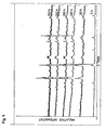
- Fig. 1 shows the results of the comparative example.
- the relative intensity over diffraction angle (theta) is plotted for the six selected residence times of the membrane.
- the new relative intensity peaks at longer run times compared to the 0h curve indicate, inter alia, the formation of elemental Co as well as of various independent oxide phases.
- the peaks of the perovskite phase crucial for oxygen permeation disappear. It is obvious that even at residence times of only 50 h, a significant degradation of the crystal structure occurs, which is associated with a loss of the proper functionality of the membrane, that leads to a local decomposition.
- the teaching discloses a reactor as apparatus for carrying out a chemical reaction in which an oxygen-containing gas is passed through a tube of an oxygen-containing membrane, which is surrounded by a catalytically active material and this catalytically active material is surrounded by another inert porous material, whereby the arrangement is kept physically stable and the membrane is protected from destruction by the reducing reaction gas.
- the membrane and the catalytically active material are such that they do not react with one another under the reaction conditions or are physically separated from one another, for example by so-called "spacers".
- the catalytically active material may be in any geometric shape, with discs, tubes or sealed tubes being exemplified. Examples of possible reactions are the partial oxidation of methane, natural gas, or light hydrocarbons, with or without entrained carbon dioxide, and the decomposition of nitrogen oxides, sulfur oxides, carbon dioxide and hydrogen sulfide by oxygen.
- the US 5573737 describes a hollow reaction tube as a reactor for the partial oxidation of hydrocarbons, which is composed of several layers, wherein the outer tube consists of an oxygen-permeable perovskite, the inner tube consists of a doped zirconium oxide, and the intermediate middle tube at the transition layer to the outer tube has an excess of perovskite and has an excess of zirconia at the interface to the inner tube, wherein the oxygen-containing gas is bypassed in a reactor at the outer layer of the reaction tube, and the reducing reaction gas is passed through the hollow tube.
- the installation of the middle intermediate tube ensures the stability of the inner tube made of perovskite.
- the inner tube made of the perovskite material assumes the function of oxygen permeation from the oxygen-containing gas into the reaction gas.
- the object of the prior art is therefore to develop an oxidation reactor with an oxygen-conducting membrane, the membrane having a high reduction stability and high mechanical stability.
- the present invention solves this object by an oxidation reactor according to claim 1, comprising a supply line for an oxygen-containing gas, which leads into a distributor space or a distributor element. Furthermore, the oxidation reactor comprises a supply line for a raw or fully oxidized raw gas, which leads into a reaction space, wherein in the reaction space a plurality of gas-tight oxygen-conducting membrane elements are arranged.
- the present invention further achieves the object by a reactor in which the membrane elements in the form of a bundle or a group of membrane elements woven or twisted parallel to one another are usable.
- the membrane elements have an inlet and an outlet surface with respect to the oxygen transport, wherein the outlet surface is defined as an outer surface which is arranged on the side of the reaction space.
- the membrane elements represent the spatial connection of distributor space and a collecting space and / or an outlet. During operation of the reactor, the oxygen-containing gas can flow through these in the order: inlet, distribution space, membrane elements, collecting space and / or outlet, the reaction space being filled with catalyst is.
- a defined minimum distance between the outer surface of a composite of membrane elements is ensured by means of one or more spacer elements to the fillable catalyst.
- the composite may be a bundle or group of parallel or interwoven or twisted membrane elements.
- the spacer elements of the reactor according to the invention are inert shaped bodies which encase the membrane elements as a bundle or group or are upstream of the reaction space.
- the moldings may be present as a bed and / or be formed as a single element, such as a jacket tube.
- the inert material in this case has a pore volume or a perforation which is smaller than the fine grain content of the fillable catalyst.
- the spacer elements can be formed from one or more inert materials which adhere directly to the outer membrane surface. Spacer elements of such a shape would prevent the catalyst from direct contact with the oxygen-conducting membrane elements by a suitable pore structure, which is smaller than the fines content of the catalyst bed.
- spacer elements are catalytically active moldings which are oxidized and thereby rendered inert in those areas during normal operation of the reactor which are arranged opposite and / or touching the outlet surface of the membrane.
- the shaping of the spacer elements in the oxidation reactor according to the invention is either regular or has an irregular structure.
- the spacer elements can be further improved by having one or more catalytically active surfaces.
- the spacer elements are shaped such that the surfaces facing the reaction space are coated with catalytically active material or formed from catalytically active material.
- the membrane elements of the two aforementioned oxidation reactors are formed from one or more of the materials selected from the group of perovskites (ABO 3 ), perovskite-related structures, fluorite structures (AO 2 ), Aurivillius structures ([Bi 2 O 2 ] [A n -1 B n O x ]) or the Brownmillerit Scheme (A 2 B 2 O 5 ) come.
- ABO 3 perovskites
- perovskite-related structures fluorite structures
- AO 2 fluorite structures
- Aurivillius structures [Bi 2 O 2 ] [A n -1 B n O x ]
- Brownmillerit Scheme A 2 B 2 O 5
- membrane elements which are formed from one or more of the materials which can be described by the following general structural formulas: La 1-x (Ca, Sr, Ba) x Co 1-y Fe y O 3 - ⁇ , Ba (Sr) Co 1-x Fe x O 3- ⁇ , Sr (Ba) Ti (Zr) 1-xy Co y Fe x O 3- ⁇ , BaCo x Fe y Zr 1-xy O 3- ⁇ , La 1-x Sr x Ga 1-y Fe y O 3 - ⁇ , La 2 Ni x Fe y O 4- ⁇ , La 0.5 Sr 0.5 MnO 3- ⁇ , La Fe (Ni) O 3- ⁇ or La 0.9 Sr 0.1 FeO 3- ⁇ .
- the membrane elements in this case have an oxygen permeance, which at 950 ° C and a oxygen partial pressure difference of> 0.1 bar between the located on both sides of the membrane elements free gas phases on average equal to or greater than 0.1 Nm 3 / (m 2 h) is.
- gas to be oxidized is preferably methane or natural gas with a high methane content, which may also contain non-oxidisable constituents.
- the invention also includes the use of the abovementioned oxidation process in one of the embodiments for the production of synthesis gas with the main components H 2 and CO. Also encompassed by the invention is the use of the oxidation process according to the invention for the oxidative dehydrogenation of alkanes, the oxidative methane coupling, the partial oxidation of higher hydrocarbons and / or hydrocarbon derivatives or the selective oxidation of individual constituents of gas mixtures,
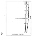
- the entire reactor was operated continuously at 850 ° C for several hundred hours. During operation, oxygen permeates from the air side through the membrane and was converted on the permeate side with methane to synthesis gas.
- An exemplary diagram for the composition of the product gas shows Fig. 3 , It is obvious that the composition of the synthesis gas phase given in this experiment corresponds approximately to the composition of the comparative example.
- the reason for this unexpected stability could be the formation of an oxygen protective layer over the membrane in the described reactor system. It is assumed that, due to the porous Al 2 O 3 tube arranged around the membrane, an increased mass transfer resistance of the oxygen from the permeate-side membrane surface to the catalyst is built up. Thus, a local maximum of the oxygen concentration forms directly on the permeate side surface of the membrane, thereby protecting it from destruction.
- a suitable reactor can thus be developed to suit the respective membrane material.
- the extent of oxygen mass transport inhibition on the permeate side can thus be adjusted so that a local oxygen protection layer of the desired intensity is formed over the membrane surface.
- Crucial here is the targeted removal of oxygen from the permeate side of the membrane, so that the subsequent conversion of the oxygen is braked on the catalyst.
- it is not crucial to transport the mass of the reactive media, such as methane or hydrogen, towards the membrane, since the protection of the membrane does not result from a low concentration of the reactive component on the permeate side surface of the membrane. The protection results rather from the fact that a sufficiently slow removal of the oxygen is coupled with a simultaneously sufficiently high oxygen permeation through the membrane. As a consequence, a significant amount of free oxygen is locally present at the permeate-side membrane surface.
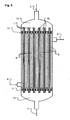
- These connecting elements 10 may be, for example drilled steel plates, in which the individual membrane modules are glued.
- the bundle of Membranfasem can as in Fig. 5 be arranged as a plurality of parallel individual fibers or in the form of interconnected fiber bundles according to DE 10 2005 005 464.1 available.
- the oxygen-providing stream 5 flows through the fibers and releases some or all of its contained oxygen through the membrane elements into the fiber space. Subsequently, the oxygen depleted residual stream 7 leaves the fiber bundle.
- the catalyst bed 9 is flowed through by the stream 6 to be oxidized, the latter being reacted by reaction with the oxygen permeated through the membrane 1 and optionally further reactions to the product stream 8.
- the invention is not limited to the above constructive examples.
- the reactor according to the invention and the process are furthermore applicable not only to the production of synthesis gas by means of mixed-conducting membrane elements but also to further oxidation reactions in which oxygen-transporting membrane elements can be usefully used.
- Examples of such applications are the oxidative dehydrogenation of alkanes, the oxidative methane coupling, the partial oxidation of higher hydrocarbons and / or hydrocarbon derivatives or the selective oxidation of individual constituents of gas mixtures.
Landscapes
- Chemical & Material Sciences (AREA)
- Chemical Kinetics & Catalysis (AREA)
- Organic Chemistry (AREA)
- Engineering & Computer Science (AREA)
- Inorganic Chemistry (AREA)
- Combustion & Propulsion (AREA)
- Materials Engineering (AREA)
- Analytical Chemistry (AREA)
- Health & Medical Sciences (AREA)
- Physics & Mathematics (AREA)
- Fluid Mechanics (AREA)
- General Health & Medical Sciences (AREA)
- Oil, Petroleum & Natural Gas (AREA)
- General Chemical & Material Sciences (AREA)
- Organic Low-Molecular-Weight Compounds And Preparation Thereof (AREA)
- Separation Using Semi-Permeable Membranes (AREA)
- Physical Or Chemical Processes And Apparatus (AREA)
- Catalysts (AREA)
- Hydrogen, Water And Hydrids (AREA)
Description
- Die Erfindung richtet sich auf einen Oxidationsreaktor und ein Verfahren zum Einsatz dieses Reaktors, in welchem eine Vielzahl von gasdichten sauerstoffleitenden Membranelementen angeordnet sind, deren äußere Oberflächen auf der Seite eines mit Katalysator befüllbaren Reaktionsraumes angeordnet sind, und die mit einem sauerstoffhaltigen Gas durchströmbaren Membranelemente die räumliche Verbindung von Verteilerraum und einem Sammelraum und/oder einem Auslass des Reaktors darstellen. Der Reaktor ist dadurch gekennzeichnet, dass mittels eines oder mehrerer Distanzelemente ein definierter Mindestabstand zwischen der äußeren Oberfläche eines Membranelements und dem Katalysator des Reaktionsraumes sichergestellt ist.
- Synthesegas, d. h. Gasgemische mit den Hauptbestandteilen CO und H2 (sowie ggf. je nach Herstellung und Reinigungsschritten weiteren Komponenten wie z. B. CO2, H2, N2 und inerte Bestandteile), wird dem heutigen Stand der Technik zu Folge hauptsächlich auf zwei Wegen hergestellt: dem endothermen Steamreforming von Kohlenwasserstoffen (z. B. Methan) oder abgeleiteten Verbindungen gemäß
H2O+ CH4 ⇄ CO + 3 H2 ΔRH0 298 = 206 kJ/mol (1),
sowie der direkten Umsetzung dieser Verbindungen mit Sauerstoff in einer-zumindest formal - partiellen Oxidation gemäß
CH4 + ½ O2 → CO + 2 H2 ΔRH0 298 = -36 kJ/mol (2).
- Der für die partielle Oxidation benötigte Sauerstoff kann dabei beispielsweise aus einer kryogenen Luftzerlegungsanlage stammen.
- Beim dem im Stand der Technik üblichen Steamreforming zur Synthesegasherstellung sind insbesondere die hohen Investitionskosten sowie die im Betrieb freiwerdende große Abhitzemenge nachteilig. Im Falle der partiellen Oxidation gemäß (2) ist hingegen u. a. die Notwendigkeit zum Einsatz von teurem Sauerstoff als nachteilig zu bewerten, welcher mittels einer separaten Luftzerlegungsanlage bereitgestellt wird. Da im allgemeinen Stickstoff im späteren Synthesegas unerwünscht ist, kann keine direkte Zugabe von Luft als Oxidationsmedium erfolgen.
- Es wäre wirtschaftlich sehr vorteilhaft, wenn man den erforderlichen Sauerstoff bei der Herstellung von Synthesegas ohne zusätzlichen Verfahrensschritt direkt mittels einer gemischtleitenden Membran in einen Oxidationsreaktor einbringen könnten und hierzu sogar Luft als O2-Lieferant nutzen könnte.
- Hierzu sind im Labormaßstab Verfahren bekannt, welche zur Herstellung von Synthesegas Reaktoren mit so genannten gemischtleitenden Membranen einsetzen. Diese noch im Entwicklungsstadium befindlichen gemischtleitenden Materialien zur Bereitstellung des Sauerstoffes sind Verbindungen, welche unter geeigneten Betriebsbedingungen die Fähigkeit zur Leitung von Elektronen und zur Leitung von Sauerstoffionen jeweils in einem signifikanten Maße zeigen. Von untergeordneter Bedeutung sind weiterhin ausschließlich sauerstoffionenleitende Materialien ohne die Fähigkeit zur Elektronenleitung, bei welchen der notwendige Ladungsausgleich über einen zusätzlichen externen Stromkreis gewährleistet werden muss,
- Werden derartige gemischtleitende Materialien zu gasdichten oder nahezu gasdichten Membranen verarbeitet und auf Betriebstemperatur erwärmt, so ergibt sich bei Vorliegen eines Sauerstoffpartialdruckgradienten zwischen den beiden Seiten der Membran unter Nutzung von Gitterfehlstellen ein Sauerstofffluss durch die Membran entsprechend dem vorliegenden Partialdruckgradienten
Feedseite O2 + 4 e- → 2 O2- (3)
Permeatseite 2 O2- → O2 + 4 e- (4)
- Für jedes auf der Permeatseite in den Reaktionsraum abgegebene O2-Molekül wird die Ladung von 4 e- frei, welche entgegen der Richtung des Sauerstoffflusses zur Feedseite transportiert wird.
- Der Transport des Sauerstoffes erfolgt dabei in ionischer Form, d. h. es ergibt sich eine theoretische Selektivität einer dichten Membran bezüglich Sauerstoff von unendlich. Im Falle einer defektfreien Membran wird somit beispielsweise bei Einsatz von Luft als sauerstofflieferndes Medium eine Abtrennung des Sauerstoffes von den restlichen Luftbestandteilen wie Stickstoff ermöglicht.
- Wie vorstehend genannt, ist es im Stand der Technik bekannt, Oxidationsreaktionen unter Nutzung sauerstoffleitender Materialien durchzuführen, wobei ein Reaktor eingesetzt wird, welcher durch eine gemischtleitende Membran in zwei Räume oder Bereiche unterteilt ist. Im Betrieb wird auf einer Seite der Membran oder des Membranmoduls ein sauerstofflieferndes Gas oder Gasgemisch vorgelegt, während auf der gegenüberliegenden Seite der Membran, welche im Folgenden als äußere Oberfläche bzw. Permeatseite bezeichnet wird, ein zu oxidierendes Medium vorgelegt wird. Ein derartiger Membranreaktor wird beispielsweise in
US 5,820,655 A beschrieben. Sauerstoffliefernde Gase sind dabei häufig Wasserdampf, CO2 oder bevorzugt Luft. Im Betrieb permeiert Sauerstoff von der Seite des höheren Sauerstoffpartialdruckes kommend durch die Membran und reagiert mit dem auf der gegenüberliegenden Seite befindlichen oxidierbaren Medium. Im Falle der Herstellung von Synthesegas ist das oxidierbare Medium bevorzugt ein Kohlenwasserstoff wie etwa Methan oder Erdgas mit einem hohen Methananteil, welchem zur Verhinderung einer möglichen Verkokung typischerweise Wasserdampf zugesetzt wird. - Da der Sauerstoff auf der Permeatseite ständig abreagiert, liegt der Sauerstoffpartialdruck der Permeatseite unter dem Sauerstoffpartialdruck der Feedseite, so dass weiter Sauerstoff permeiert. Daher kann beispielsweise auf der Feedseite Luft mit einem mehr oder weniger beliebigen Druck eingesetzt werden, während gleichzeitig auf der Permeatseite ein deutlich erhöhter Druck herrscht. Als untere Grenze für den Druck auf der Feedseite gilt, dass der Sauerstoffpartialdruck der Feedseite über dem Sauerstoffpartialdruck der Permeatseite liegen muss.
- Um beispielsweise bei der Herstellung von Synthesegas akzeptable Reaktionsgeschwindigkeiten und damit auch integrale Selektivitäten auf der Permeatseite zu erreichen, wird typischerweise in dem Reaktionsraum des Reaktors ein geeigneter Katalysator eingesetzt. Beispiele dafür finden sich etwa in
EP 0 999 180 A2 ,EP 1 035 072 A1 ,
US 6,077,323 oderUS 6,695,983 . Bei Betriebsbedingungen permeiert Sauerstoff von der Feedseite kommend durch die Membran und wird auf der gegenüberliegenden Permeatseite umgesetzt. Die treibende Kraft für diese Permeation ist die Sauerstoffpartialdruckdifferenz zwischen den beiden Seiten der Membran. Da diese durch die Abreaktion des Sauerstoffes ständig aufrechterhalten wird, kann im Fall der Synthesegaserzeugung mit Luft auf der Feedseite und einem Kohlenwasserstoff/Wasserdampf-Gemisch auf der Permeatseite die Luft mit Umgebungsdruck oder nur leicht erhöhtem Druck eingesetzt werden. - Bei den gemischtleitenden Materialien handelt es sich typischerweise um keramische Materialien, welche aufgrund einer Sauerstoffdefektstruktur bei geeigneten Betriebsbedingungen über die Fähigkeit zur Leitung von Sauerstoffionen verfügen. Geeignete Betriebsbedingungen sind dabei eine hinreichend hohe Temperatur von typischerweise über 600°C sowie eine Sauerstoffpartialdruckdifferenz über das keramische Material. Derartige Materialien können beispielsweise der Gruppe der Perowskit- (ABO3) bzw. perowskitverwandten Strukturen, der Fluoritstrukturen (AO2), der Aurivilliusstrukturen ([Bi2O2][An-1BnOx]) oder der Brownmilleritstrukturen (A2B2O5) entstammen. Ebenso denkbar sind Kompositmaterialien aus ionenleitenden und elektronenleitenden Materialien. Typische Beispiele für in der Literatur als sauerstoffleitende Materialien bzw. Materialklassen aufgeführte Systeme sind La1-x(Ca,Sr,Ba)xCo1-yFeyO3-δ, Ba(Sr)Co1-xFexO3-δ, Sr(Ba)Ti(Zr)1-x-y. CoyFexO3-δ, La1-xSrxGa1-yFeyO3-δ, La0,5Sr0,5MnO3-δ, LaFe(Ni)O3-δ, La0,9Sr0,1FeO3-δ oder BaCoxFeyZr1-x-yO3-δ. (A. Thursfield, I. S. Metcalfe, J. Mat. Sci., 2004, 14, 275-2485)
- Ferner können beispielsweise mehrphasige Kompositmaterialien zum Einsatz kommen. Für einen technischen Einsatz nutzbare Materialien sind jene, welche eine möglichst hohe Sauerstoffpermeanz aufweisen. Typische Werte liegen hier in der Größenordnung von >0.1 Nm3/(m2h) Sauerstoff.
- Problematisch ist jedoch die chemische und mechanische Stabilität der Membranen. So kann durch den Fachmann errechnet werden, dass der Gleichgewichtssauerstoffpartialdruck in einem Synthesegasstrom gängiger Zusammensetzung bei 900°C und 30 bar Gesamtdruck weniger als 10-16 bar beträgt.
- Andererseits sind die als gemischtleitende Membranen eingesetzten Materialien im Allgemeinen oxidische Keramiken, welche unterhalb eines von den Bestandteilen der Membran abhängigen Sauerstöffpartialdruckes zur Reduktion und damit Zerstörung der Kristallstruktur neigen. Durch den Fachmann kann beispielsweise leicht errechnet werden, dass das häufig in derartigen Materialien vorkommende CoO bei einer Temperatur von 900°C und dem genannten Sauerstoffpartialdruck von unter 10-16 bar zu elementarem Co reduziert wird. Diese theoretische Abschätzung lässt sich auch experimentell untermauern, wie in dem Vergleichsbeispiel gezeigt wird.
- Eine weitere Gefahr derart hoher Sauerstoffpartialdruckgradienten ergibt sich aus möglicherweise auftretenden chemisch induzierten Spannungen. In Abhängigkeit von der Höhe des jeweiligen Sauerstoffpartialdrucks auf den beiden Seiten der Membran bilden sich unterschiedliche Sauerstoffdefektstrukturen innerhalb des Kristallgitters der Membran aus. Dies führt zu unterschiedlichen Gitterkonstanten des Kristallgitters auf der Feed- und der Permeatseite der Membran. Die dadurch induzierte mechanische Belastung, welche auch als chemisch induzierte Spannung bezeichnet wird, führt unter Umständen zu einer Zerstörung der Membran.
- Proben des für gemischtleitende Membranen geeigneten Materials Ba(Co,Fe,Zr)O3-δ. welches nachstehend mit BCFZ bezeichnet wird (Journal of Membrane Science, 2005, 258, 1-4) wurden bei 850°C und einem Druck von 1 bar einer Synthesegasatmosphäre der folgenden Zusammensetzung ausgesetzt:
CO2 7 Vol.-% CO 24 Vol.-% H2 56 Vol.-% H2O 7 Vol.-% CH4 6 Vol.-% - Anschließend wurde mittels X-Ray Diffraction (XRD) die Kristallstruktur der Proben in Abhängigkeit von der Verweildauer bestimmt.
Fig. 1 zeigt die Resultate des Vergleichsbeispiels. In dieser Darstellung ist für die sechs gewählten Verweilzeiten der Membran, die Relative Intensität über Beugungswinkel (Theta) aufgetragen. Die gegenüber dem 0h-Verlauf aufgetretenen neuen Peaks der relativen Intensität bei längeren Laufzeiten, deuten u.a. auf die Bildung von elementarem Co sowie verschiedener eigenständiger Oxidphasen hin. Gleichzeitig verschwinden die Peaks der für die Sauerstoffpermeation entscheidenden Perowskitphase. Es ist offensichtlich, dass bereits bei Verweilzeiten von nur 50 h eine signifikante Degradation der Kristallstruktur auftritt, welche mit einem Verlust der bestimmungsgemäßen Funktionsfähigkeit der Membran verbunden ist, also zu einer lokalen Zersetzung führt. - Zusätzlich zu dieser Zerstörung der Membran ist bei Anwesenheit von Luft auf einer Seite der Membran eine Ausbildung von unterschiedlichen Gitterkonstanten auf beiden Seiten der Membran mit der Folge mechanischer Belastungen in Folge chemisch induzierten Spannungen zu beobachten (F. Boroomand, E. Wessel, H. Bausinger, K. Hilpert, Solid State Ionics, 2000, 129, 251-258; S. B. Adler, J. Am. Ceram. Soc., 2001, 84, 2117-2119)
- Es ist folglich sowohl auf experimenteller als auch auf theoretischer Basis zu befürchten, dass eine keramische Membran mit der Zusammensetzung BCFZ bei der Nutzung zur Herstellung von Synthesegas zerstört wird, so dass trotz der grundsätzlich geeigneten Materialeigenschaft bisher keine industrielle Nutzung möglich erschien.
- Weiterhin ist bei einer direkten Anlagerung von Katalysatormaterial an der Membran zu befürchten, dass bei der erforderlichen Temperatur von über 800°C chemische Feststoffreaktionen im Kontaktbereich der Oberflächen stattfinden, welche ebenfalls zur Schädigung oder lokalen Zerstörung der Membran führen können.
- Eine Möglichkeit zur Umgehung dieser Zerstörung wird in
EP 0,999,180 A2 offenbart. Bestandteil dieser Schrift ist die gezielte Zugabe von Oxygenaten wie CO2 oder Wasserdampf zur Permeatseite der Membran. Hierdurch erhöht sich der Gleichgewichtssauerstoffpartialdruck auf der Permeatseite der Membran auf einen Wert, welcher oberhalb des zur Reduktion der Membran führenden Sauerstoffpartialdruckes liegt. Problematisch ist hierbei jedoch der erhöhte Aufwand hinsichtlich Investitions- und Betriebskosten aufgrund der notwendigen Gasrückführung innerhalb der Anlage sowie die begrenzte Variationsbreite des Gleichgewichtssauerstoffpartialdruckes. Bei den durch die Anhebung typischerweise erreichbaren Gleichgewichtssauerstoffpartialdrücken auf der Permeatseite von etwa 10-10 bar werden die üblichen Membranmaterialien zwar nicht mehr reduziert, chemisch induzierte Spannungen treten jedoch weiterhin auf. Diese Rückführung von Oxygenaten ist daher nicht generell dafür geeignet, neben der Reduktionsstabilität der keramischen Membran auch deren mechanische Stabilität zu verbessern und verschlechtert natürlich auch die Wirtschaftlichkeit eines solchen Verfahrens. - Eine weitere Möglichkeit, die reduktive Zerstörung der Membran zu vermeiden, beschreibt die
US 2003/0218991 A1 . Die Lehre offenbart einen Reaktor als Vorrichtung zur Durchführung einer chemischen Reaktion, bei der ein sauerstoffhaltiges Gas durch ein Rohr aus einer sauerstoffhaltigen Membran geführt wird, welche von einem katalytisch aktiven Material umgeben ist und dieses katalytisch aktive Material von einem weiteren inerten porösen Material umgeben ist, wodurch die Anordnung physikalisch stabil gehalten wird und die Membran vor der Zerstörung durch das reduzierende Reaktionsgas geschützt wird. Die Membran und das katalytisch aktive Material sind so beschaffen, dass sie unter den Reaktionsbedingungen nicht miteinander reagieren oder physikalisch, beispielsweise durch sogenannte "Spacer", voneinander getrennt sind. Das katalytisch aktive Material kann in beliebiger geometrischer Form vorliegen, wobei Scheiben, Rohre oder verschlossene Rohre als Beispiele genannt werden. Bespiele für mögliche Reaktionen sind die partielle Oxidation von Methan, Erdgas, oder leichten Kohlenwasserstoffen, mit oder ohne mitgeführtem Kohlendioxid, und die Zersetzung von Stickoxiden, Schwefeloxiden, Kohlendioxid und Schwefelwasserstoff durch Sauerstoff. - Die
US 5573737 beschreibt ein hohles Reaktionsrohr als Reaktor für die partielle Oxidation von Kohlenwasserstoffen, welches aus mehreren Schichten aufgebaut ist, wobei das äußere Rohr aus einem sauerstoffpermeablen Perovskit besteht, das innere Rohr aus einem dotierten Zirkonoxid besteht, und das dazwischenliegende mittlere Rohr an der Übergangsschicht zum äußeren Rohr einen Überschuss an Perovskit aufweist und an der Übergangsschicht zum inneren Rohr einen Überschuss an Zirkondioxid aufweist, wobei das sauerstoffhaltige Gas in einem Reaktor an der äußeren Schicht des Reaktionsrohres vorbeigeleitet wird, und das reduzierende Reaktionsgas durch das hohle Rohr geleitet wird. Durch den Einbau des mittleren Zwischenrohres wird die Stabilität des inneren Rohres aus Perovskit gewährleistet. Das innere Rohr aus dem Perovskitmaterial übemimmt dabei die Funktion der Sauerstoffpermeation aus dem sauerstoffhaltigen Gas in das Reaktionsgas. - Aus dem Stand der Technik ergibt sich somit die Aufgabe, einen Oxidationsreaktor mit einer sauerstoffleitenden Membran zu entwickeln, wobei die Membran eine hohe Reduktionsstabilität und hohe mechanische Stabilität aufweist.
- Die vorliegende Erfindung löst diese Aufgabe durch einen Oxidationsreaktor gemäß dem Anspruch 1, der eine Zuleitung für ein sauerstoffhaltiges Gas, welche in einen Verteilerraum oder ein \/erteilerelement führt, umfasst. Weiterhin umfasst der Oxidationsreaktor eine Zuleitung für ein ganz oder teilweise zu oxidierendes Rohgas, welche in einen Reaktionsraum führt, wobei in dem Reaktionsraum eine Vielzahl von gasdichten sauerstoffleitenden Membranelementen angeordnet sind. Die vorliegende Erfindung löst die Aufgabe weiterhin durch einen Reaktor, in dem die Membranelemente in Form eines Bündels oder einer Gruppe parallel miteinander verwobener oder verwundener Membranelemente verwendbar sind.
- Die Membranelemente weisen bezogen auf den Sauerstofftransport eine Eintritts- und eine Austrittsfläche auf, wobei die Austrittsfläche als äußere Oberfläche definiert ist, die auf der Seite des Reaktionsraumes angeordnet ist. Die Membranelemente stellen die räumliche Verbindung von Verteilerraum und einem Sammelraum und/oder einem Auslass dar. Das sauerstoffhaltige Gas kann im Betrieb des Reaktors diesen in der Reihenfolge: Einlass, Verteilerraum, Membranelemente, Sammelraum und/oder Auslass durchströmen, wobei der Reaktionsraum mit Katalysator befüllbar ist.
- Dabei wird mittels eines oder mehrerer Distanzelemente ein definierter Mindestabstand zwischen der äußeren Oberfläche eines Verbundes von Membranelementen zum einfüllbaren Katalysator sichergestellt. Der Verbund kann dabei ein Bündel oder Gruppe paralleler oder miteinander verwobener oder verwundener Membranelemente sein.
- Vorteilhafterweise sind die Distanzelemente des erfindungsgemäßen Reaktors inerte Formkörper, welche die Membranelemente als Bündel oder Gruppe umhüllen oder zum Reaktionsraum hin vorgelagert sind. Die Formkörper können dabei als Schüttung vorliegen und/oder als Einzelelement, wie beispielsweise ein Mantelrohr, geformt sein. Das inerte Material weist dabei ein Porenvolumen oder eine Perforation auf, welche kleiner als der Feinkornanteil des einfüllbaren Katalysators ist.
- Die Distanzelemente können in einer weiteren Ausführungsform aus ein oder mehreren inerten Materialien gebildet sein, welche direkt auf der äußeren Membranoberfläche anhaften. Distanzelemente einer derartigen Form würden durch eine geeignete Porenstruktur, welche kleiner als der Feinanteil der Katalysatorschüttung ist, den Katalysator vom direkten Kontakt mit den sauerstoffleitenden Membranelementen abhalten.
- Eine vergleichbare Rückhaltung kann erreicht werden, wenn die Distanzelemente katalytisch wirksame Formkörper sind, welche in denjenigen Bereichen bei bestimmungsgemäßem Betrieb des Reaktors oxidiert und dadurch inertisiert werden, welche der Austrittsfläche der Membran gegenüberliegend und/oder berührend angeordnet sind.
- Die Formgebung der Distanzelemente in dem erfindungsgemäßen Oxidationsreaktor ist dabei entweder regelmäßig oder weist eine unregelmäßige Struktur auf. Die Distanzelemente können weiterhin dadurch verbessert werden, dass diese eine oder mehrere katalytisch aktive Oberflächen aufweisen. Idealerweise sind die Distanzelemente derart geformt, dass die zum Reaktionsraum weisenden Oberflächen mit katalytisch aktivem Material beschichtet oder aus katalytisch aktivem Material gebildet sind.
- In einer vorteilhaften Ausführungsform sind die Membranelemente der beiden vorgenannten Oxidationsreaktoren aus einem oder mehreren der Materialien gebildet, welche aus der Gruppe der Perowskite (ABO3), perowskitverwandten Strukturen, Fluoritstrukturen (AO2), Aurivilliusstrukturen ([Bi2O2][An-1BnOx]) oder der Brownmilleritstrukturen (A2B2O5) stammen. Besonders geeignet für den O2-Transport und somit die Nutzung in dem erfindungsgemäßen Oxidationsreaktor sind Membranelemente, die aus einem oder mehreren der Materialien gebildet ist, welche durch folgende allgemeine Strukturformeln beschrieben werden können: La1-x(Ca,Sr,Ba)xCo1-yFeyO3-δ, Ba(Sr)Co1-xFexO3-δ, Sr(Ba)Ti(Zr)1-x-yCoyFexO3-δ, BaCoxFeyZr1-x-yO3-δ, La1-xSrxGa1-yFeyO3-δ, La2NixFeyO4-δ, La0,5Sr0,5MnO3-δ, LaFe(Ni)O3-δ oder La0,9Sr0,1FeO3-δ.
- Idealerweise weisen die Membranelemente dabei eine Sauerstoffpermeanz auf, die bei 950°C und einer Sauerstoffpartialdruckdifferenz von >0,1 bar zwischen den sich auf den beiden Seiten der Membranelemente befindlichen freien Gasphasen im Mittel gleich oder größer als 0,1 Nm3/(m2h) ist.
- Von der Erfindung ist weiterhin ein Verfahren zur Oxidation von Stoffen umfasst, bei welchem ein Oxidationsreaktor nach einem der vorstehenden Ausführungsformen eingesetzt wird, dessen Reaktionsraum mit einem Katalysator gefüllt ist und
- Sauerstoff oder ein sauerstoffhaltiges Gas über den Einlass in den Verteilerraum des Oxidationsreaktors geleitet wird,
- in den Reaktionsraum ein zu oxidierendes Gas oder Gasgemisch geleitet wird,
- wobei die Temperatur im Reaktionsraum zwischen 200 - 1200°C, bevorzugt 500 - 1000°C und idealerweise 700 - 900°C beträgt und weiterhin
- der Druck zwischen 1 - 200 bar, bevorzugt 10 - 70 bar und idealerweise 30 bis 60 bar beträgt.
- Eine vorteilhafte Ausführungsform des Oxidationsverfahrens sieht vor, dass das zu oxidierende Gas bevorzugt Methan oder Erdgas mit einem hohen Methananteil ist, welches auch nichtoxiderbare Bestandteile enthalten kann.
- Weiterhin ist von der Erfindung auch die Verwendung des vorstehend genannten Oxidationsverfahrens in einer der Ausführungsformen für die Herstellung von Synthesegas mit den Hauptkomponenten H2 und CO umfasst. Auch von der Erfindung umfasst ist der Einsatz des erfindungsgemäßen Oxidationsverfahrens für die oxidative Dehydrierung von Alkanen, die oxidative Methankupplung, die partielle Oxidation höherer Kohlenwasserstoffe und/oder Kohlenwasserstoffderivate oder die selektive Oxidation einzelner Bestandteile von Gasgemischen,
- Anhand des nachstehenden Beispiels werden die Vorteile des erfindungsgemäßen Oxidationsreaktors und des Verfahrens belagt.
- Zur Herstellung von Synthesegas wurde aus dem an und für sich unter den zu erwartenden Bedingungen thermodynamisch instabilen Material BCFZ Hohlfasern mit folgenden Abmessungen hergestellt (Journal of Membrane Science, 2005, 258, 1-4):
- Länge 30 cm
- Außendurchmesser ca. 1,5 mm
- Wandstärke etwa 200 µm
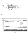
- Ein nachstehend näher beschriebener und in
Fig. 2 skizzierter Oxidationsreaktor, der die Erfindung nicht darstellt, kam zum Einsatz Eine als Hohlfaser geformte Membran 1, nachstehend auch Membranmodul genannt, aus dem vorgenannten Material wurde in einen Reaktionsraum 2 eingebaut, wobei die Membran 1 von etwa 1,5 cm langen Bruchstücken eines porösen Al2O3-Rohres 3 mit einem Durchmesser von 3 mm umgeben war. Auf der Außenseite dieser Al2O3-Rohres 3 wurde ein als gepunktete Fläche dargestellter Nickel-Katalysator 4 aufgebracht. Der Nickel-Katalysator 4 ist ein üblicher Oxidationskatalysator zum Steamreforming oder zur Oxidation von Methan. Im Betrieb wurde die Membran 1 auf der Hohlfaserinnenseite mit Luft 5 mit einem Druck von 1 bar durchströmt. während in den Reaktionsraum 2 außerhalb der Membran 1 mit Methan 6 unter einem Druck von 1 bar eingeleitet wurde. Der bezüglich Sauerstoff abgereicherte Ausgangsstrom 7 und der Produktstrom 8 werden abgeleitet. Die einzelnen Gasströme werden getrennt in den Oxidationsreaktor gegeben bzw. aus diesem entnommen, ohne dass eine Vermischung der Ströme erfolgt. - Der gesamte Reaktor wurde bei 850°C kontinuierlich über mehrere hundert Stunden betrieben. Während des Betriebes permeiert Sauerstoff von der Luftseite kommend durch die Membran und wurde auf der Permeatseite mit Methan zu Synthesegas umgesetzt. Ein beispielhaftes Diagramm für die Zusammensetzung des Produktgases zeigt
Fig. 3 . Es ist offensichtlich, dass die bei diesem Versuch gegebene Zusammensetzung der Synthesegasphase in etwa der Zusammensetzung des Vergleichsbeispiels entspricht. - Nach Abschluss des Versuches wurde die Membran einer XRD-Analyse unterzogen, welche mit einer entsprechenden XRD-Analyse der fischen Membran verglichen wurde. Das in
Fig. 4 gezeigte Resultat macht durch die Identität der Kurvenverläufe der frischen Membran und der Membran nach 600 Stunden Einsatz deutlich, dass entgegen den theoretischen Erwartungen und den inFig. 1 dargestellten experimentellen Ergebnissen des Vergleichsbeispiels, auch über einen Zeitraum von mehreren hundert Stunden keine Veränderung der Kristallstruktur eintrat, d.h. die Membran war unter diesen Umständen im vorliegenden Reaktorsystem überraschender Weise stabil. Daneben ist inFig. 3 mit zunehmender Nutzungsdauer sogar ein leichter Anstieg an H2 und CO im Synthesegas zu beobachten. - Der Grund für diese unerwartete Stabilität könnte die Ausbildung einer Sauerstoff— Schutzschicht über der Membran im beschriebenen Reaktorsystem sein. Es wird vermutet, dass aufgrund des um die Membran angeordneten porösen Al2O3-Rohres, ein erhöhter Stofftransportwiderstand des Sauerstoffes von der permeatseitigen Membranoberfläche zum Katalysator aufgebaut wird. Es bildet sich somit ein lokales Maximum der Sauerstoffkonzentration direkt an der permeatseitigen Oberfläche der Membran, wodurch diese vor einer Zerstörung geschützt wird.
- Durch die Variation von Dicke, Porenstruktur und Anordnung der Distanzelemente sowie der Strömungsbedingungen im Membranmodul und insbesondere im Reaktionsraum kann somit passend auf das jeweilige Membranmaterial ein geeigneter Reaktor entwickelt werden.
- Durch den Einsatz von Distanzelementen zwischen äußerer Membranoberfläche und Katalysator kann somit das Ausmaß der Sauerstoff-Stofftransporthemmung auf der Permeatseite so eingestellt werden, dass eine lokale Sauerstoffschutzschicht der erwünschten Intensität über der Membranoberfläche gebildet wird. Entscheidend ist dabei der gezielte Abtransport des Sauerstoffes von der Permeatseite der Membran, damit die nachfolgende Umsetzung des Sauerstoffes am Katalysator gebremst wird. Dagegen nicht entscheidend ist der Stofftransport der reaktiven Medien, wie hier des Methans bzw. des Wasserstoffs, zur Membran hin, da der Schutz der Membran sich nicht durch eine geringe Konzentration der reaktiven Komponente an der permeatseitigen Oberfläche der Membran ergibt. Der Schutz ergibt sich vielmehr dadurch, dass ein hinreichend langsamer Abtransport des Sauerstoffes mit einer gleichzeitig hinreichend hohen Sauerstoffpermeation durch die Membran gekoppelt wird. In der Folge liegt an der permeatseitigen Membranoberfläche lokal eine signifikante Menge an freiem Sauerstoff vor.
-
Fig. 5 zeigt In einer schematischen Schnittdarstellung beispielhaft einen konstruktiven Aufbau des erfindungsgemäßen Oxidationsreaktors für den industriellen Einsatz. Hierbei wird die Membran 1, die als Bündel von Membranhohlfasern geformt ist, durch ein gaspermeables Rohr 3 umfasst. Außerhalb der Rohre 3 ist eine Katalysatorschüttung 9 angeordnet, die durch die gepunktete Fläche angedeutet wird. Die Enden der einzelnen Membranhohlfasern sind im Rohr 3 durch Verbindungselemente 10 geführt und in diesen fixiert. Diese Verbindungselemente 10 dienen gleichzeitig zur - Strömungsführung der Luft 5 oder eines anderen O2-liefernden Mediums in die einzelnen durch Striche angedeuteten Membranmodule,
- Abströmung der an O2 abgereicherten Luft 7 aus dem Bündel und
- gasdichten Barriere zwischen den Gasströmen 5 und 6.
- Diese Verbindungselemente 10 können beispielsweise gebohrte Stahlplatten sein, in welche die einzelnen Membranmodule eingeklebt werden. Das Bündel aus Membranfasem kann wie in
Fig. 5 angedeutet als Vielzahl von parallelen Einzelfasern angeordnet sein oder auch in Form von miteinander verbundenen Faserbündeln gemäßDE 10 2005 005 464.1 vorliegen. - Im Betrieb durchströmt der sauerstoffliefernde Strom 5 die Fasern und gibt einen Teil oder seinen gesamten enthaltenen Sauerstoff durch die Membranelemente in den Faserzwischenraum ab. Anschließend verlässt der bezüglich Sauerstoff abgereicherte Reststrom 7 das Faserbündel. Die Katalysatorschüttung 9 wird von dem zu oxidierenden Strom 6 durchströmt, wobei dieser durch Umsetzung mit dem durch die Membran 1 permeierten Sauerstoff sowie ggf. weiteren Reaktionen zum Produktstrom 8 umgesetzt wird. Die Erfindung ist dabei nicht auf die vorstehend genannten konstruktiven Beispiele beschränkt.
- Die beschriebenen Beispiele stellen keine Einschränkung der Erfindung dar, da dem Fachmann eine ganze Reihe von Möglichkeiten bekannt sind, gezielt einen Stofftransportwiderstand zwischen zwei Teilen eines Reaktors konstruktiv und/oder durch Wahl der Betriebsbedingungen zu erzeugen.
- Der erfindungsgemäße Reaktor und das Verfahren sind weiterhin neben der Herstellung von Synthesegas mittels gemischtleitender Membranelemente auch auf weitere Oxidationsreaktionen anwendbar, bei welchen sauerstofftransportierende Membranelemente sinnvoll eingesetzt werden können. Beispiele für derartige Anwendungen sind die oxidative Dehydrierung von Alkanen, die oxidative Methankupplung, die partielle Oxidation höherer Kohlenwasserstoffe und/oder Kohlenwasserstoffderivate oder die selektive Oxidation einzelner Bestandteile von Gasgemischen.
- Somit stehen dem Fachmann eine Vielzahl an bisher nicht für einsetzbar gehaltenen Membranmaterialien für industrielle Reaktoren und/oder Verfahren zur Verfügung, welche bisher aufgrund ihrer thermodynamischen und mechanischen Instabilität und sehr geringen Standzeiten nicht verwendet werden konnten.
Claims (13)
- Oxidationsreaktor, umfassend
eine Zuleitung für ein sauerstoffhaltiges Gas (5), welche in einen Verteilerraum (12) oder ein Verteilerelement führt, eine Zuleitung für ein ganz oder teilweise zu oxidierendes Rohgas (6), welche in einen Reaktionsraum (2) führt, wobei in dem Reaktionsraum (2) eine Vielzahl von gasdichten sauerstoffleitenden Membranelementen (1) angeordnet sind, welche als äußere Oberflächen bezogen auf den Sauerstofftransport eine Eintritts- und eine Austrittsfläche aufweisen, wobei die Austrittsfläche auf der Seite des Reaktionsraumes (2) angeordnet ist, und diese Membranelemente (1) die räumliche Verbindung von Verteilerraum (12) und einem Sammelraum (13) und/oder einem Auslass (8) darstellen, welche von dem sauerstoffhaltigen Gas (5) durchströmbar sind,
dadurch gekennzeichnet, dass
der Reaktionsraum (2) eine Katalysator schüttung (9) enthält, und
mittels eines oder mehrerer Distanzelemente ein definierter Mindestabstand zwischen der äußeren Oberfläche der Membranelemente (1) und dem einfüllbaren Katalysator (9) sichergestellt ist und die Membranelemente (1) als Vielzahl in Form eines Verbundes angeordnet sind, wobei ein Verbund aus einem Bündel oder einer Gruppe paralleler oder miteinander verwobener oder verwundener Membranelemente (1) besteht, und durch die Distanzelemente ein definierter Mindestabstand zwischen den äußeren Oberflächen eines Bündels oder einer Gruppe der Membranelemente (1) des Verbundes und dem einfüllbaren Katalysator (9) sichergestellt ist. - Oxidationsreaktor nach Anspruch 1,
dadurch gekennzeichnet, dass
die Distanzelemente inerte Formkörper sind, welche die Membranelemente als Bündel oder Gruppe des Verbundes umhüllen und diesen zum Reaktionsraum (2) hin vorgelagert sind, wobei die Formkörper als Schüttung vorliegen oder als Einzelelement geformt sind. - Oxidationsreaktor nach einem der Ansprüche 1 oder 2,
dadurch gekennzeichnet, dass
die Distanzelemente inerte Formkörper sind, welche die Membranelemente (1) als Bündel oder Gruppe des Verbundes umhüllen und diesen zum Reaktionsraum (2) hin vorgelagert sind, wobei das oder die inerten Formkörper als Einzelelement und dieses Einzelelement als Mantelrohr geformt ist. - Oxidationsreaktor nach einem der Ansprüche 1 bis 3,
dadurch gekennzeichnet, dass
die Distanzelemente aus einem inerten Material gebildet sind, welches direkt auf der äußeren Membranoberfläche haftet. - Oxidationsreaktor nach einem der Ansprüche 2 bis 4,
dadurch gekennzeichnet, dass
das inerte Material ein Porenvolumen aufweist, welches kleiner als der Feinkornanteil des einfüllbaren Katalysators (9) einer Katalysatorschüttung ist. - Oxidationsreaktor nach einem der Ansprüche 1 bis 5,
dadurch gekennzeichnet, dass
die Distanzelemente eine regelmäßige oder unregelmäßige Struktur aufweisen. - Oxidationsreaktor nach Anspruch 1 bis 6,
dadurch gekennzeichnet, dass
die Membranelemente (1) aus einem oder mehreren der Materialien gebildet sind, welche aus der Gruppe der Perowskite (ABO3), perowskitverwandten Strukturen, Fluoritstrukturen (AO2), Aurivilliusstrukturen ([Bi2O2][An-1BnOx]) oder der Brownmilleritstrukturen (A2B2O5) stammen. - Oxidationsreaktor nach Anspruch 1 bis 7,
dadurch gekennzeichnet, dass
die Membranelemente (1) aus einem oder mehreren der Materialien gebildet sind, welche durch folgende allgemeine Strukturformeln beschrieben werden können: La1-x(Ca,Sr,Ba)xCo1-yFeyO3-δ, Ba(Sr)Co1-xFexO3-δ, Sr(Ba)Ti(Zr)1-x-yCoyFexO3-δ. BaCoxFeyZ1-x-yO3-δ, La1-xSrxGa1-yFeyO3-δLa0,5Sr0,5MnO3-δ, La2NixFeyO4-δ, LaFe(Ni)O3-δ oder La0,9Sr0,1FeO3-δ. - Oxidationsreaktor nach Anspruch 1 bis 8,
dadurch gekennzeichnet, dass
die Membranelemente (1) eine Sauerstoffpermeanz aufweisen, die bei 950°C und einer Sauerstoffpartialdruckdifferenz von >0,1 bar zwischen den sich auf den beiden Seiten der Membran (1) befindlichen freien Gasphasen, im Mittel gleich oder größer als 0,1 Nm3/(m2h) ist. - Verfahren zur Oxidation von Stoffen,
dadurch gekennzeichnet, dass
ein Reaktor nach einem der vorstehenden Ansprüche eingesetzt wird, dessen Reaktionsraum (2) mit einem Katalysator (9) gefüllt ist und- Sauerstoff oder ein sauerstoffhaltiges Gas Ober den Einlass in den Verteilerraum des Oxidationsreaktors geleitet wird,- in den Reaktionsraum ein zu oxidierendes Gas oder Gasgemisch geleitet wird,- wobei die Temperatur im Reaktionsraum zwischen 200 - 1200°C, bevorzugt 500 - 1000°C und idealerweise 700 - 900 °C beträgt und der Druck zwischen 1 - 200 bar, bevorzugt 10 - 70 bar und idealerweise 30 bis 60 bar beträgt. - Verfahren zur Oxidation von Stoffen nach Anspruch 10,
dadurch gekennzeichnet, dass
das zu oxidierende Gas (6) auch nichtoxiderbare Bestandteile enthält und bevorzugt Methan oder Erdgas mit einem hohen Methananteil ist. - Verwendung des Verfahrens gemäß einem der Ansprüche 10 oder 11,
dadurch gekennzeichnet, dass
damit Synthesegas mit den Hauptkomponenten H2 und CO hergestellt wird. - Verwendung des Verfahrens gemäß einem der Ansprüche 10 bis 12,
dadurch gekennzeichnet, dass
dieses für die oxidative Dehydrierung von Alkanen, die oxidative Methankupplung, die partielle Oxidation höherer Kohlenwasserstoffe und/oder Kohlenwasserstoffderivate oder die selektive Oxidation einzelner Bestandteile von Gasgemischen eingesetzt wird.
Applications Claiming Priority (2)
| Application Number | Priority Date | Filing Date | Title |
|---|---|---|---|
| DE102005060171A DE102005060171A1 (de) | 2005-12-14 | 2005-12-14 | Oxidationsreaktor und Oxidationsverfahren |
| PCT/EP2006/011629 WO2007068369A1 (de) | 2005-12-14 | 2006-12-05 | Oxidationsreaktor und oxidationsverfahren |
Publications (2)
| Publication Number | Publication Date |
|---|---|
| EP1968738A1 EP1968738A1 (de) | 2008-09-17 |
| EP1968738B1 true EP1968738B1 (de) | 2012-10-31 |
Family
ID=37907494
Family Applications (1)
| Application Number | Title | Priority Date | Filing Date |
|---|---|---|---|
| EP06829277A Not-in-force EP1968738B1 (de) | 2005-12-14 | 2006-12-05 | Oxidationsreaktor und oxidationsverfahren |
Country Status (13)
| Country | Link |
|---|---|
| US (1) | US20090018373A1 (de) |
| EP (1) | EP1968738B1 (de) |
| JP (1) | JP5366556B2 (de) |
| KR (1) | KR101376082B1 (de) |
| CN (1) | CN101394924B (de) |
| CA (1) | CA2634263A1 (de) |
| DE (1) | DE102005060171A1 (de) |
| DK (1) | DK1968738T3 (de) |
| EA (1) | EA200870037A1 (de) |
| EG (1) | EG26485A (de) |
| ES (1) | ES2397966T3 (de) |
| WO (1) | WO2007068369A1 (de) |
| ZA (1) | ZA200805086B (de) |
Families Citing this family (25)
| Publication number | Priority date | Publication date | Assignee | Title |
|---|---|---|---|---|
| US7666449B2 (en) * | 2001-06-20 | 2010-02-23 | Metaproteomics, Llc | Anti-inflammatory pharmaceutical compositions for reducing inflammation and the treatment or prevention of gastric toxicity |
| WO2009071463A2 (de) * | 2007-12-03 | 2009-06-11 | Basf Se | Oxidative methankopplung via membranreaktor |
| DE102008013292A1 (de) | 2008-03-07 | 2009-09-10 | Borsig Process Heat Exchanger Gmbh | Verfahren zum Regenerieren von Sauerstoff-leitenden keramischen Membranen sowie Reaktor |
| DE102009039920A1 (de) | 2009-09-03 | 2011-03-10 | Karl-Heinz Tetzlaff | Verfahren und Vorrichtung zur Nutzung von Sauerstoff bei der Dampfreformierung von Biomasse |
| DE102009060489A1 (de) | 2009-12-29 | 2011-06-30 | Uhde GmbH, 44141 | Vorrichtung und Verfahren zur Regelung der Sauerstoffpermeation durch nicht-poröse Sauerstoffanionen leitende keramische Membranen und deren Verwendung |
| JP2012091984A (ja) * | 2010-10-28 | 2012-05-17 | Mitsubishi Heavy Ind Ltd | 高温シール材料、高温シール体、及び高温シール体を含む酸素透過モジュール |
| NL2006245C2 (en) * | 2011-02-18 | 2012-08-21 | Stichting Energie | MEMBRANE REACTOR AND PROCESS FOR THE PRODUCTION OF A GASEOUS PRODUCT WITH SUCH REACTOR. |
| CN103826685A (zh) | 2011-04-13 | 2014-05-28 | 迈克尔·科林 | 输气方法及装置 |
| CN103130748B (zh) * | 2011-11-29 | 2015-04-29 | 岳阳昌德化工实业有限公司 | 一种环己烯氧化的方法 |
| EP2607301A1 (de) * | 2011-12-20 | 2013-06-26 | Karl-Heinz Tetzlaff | Vorrichtung und Verfahren zur Erdgasreformierung |
| EP2935155B1 (de) | 2012-12-19 | 2019-02-13 | Praxair Technology Inc. | Verfahren zum abdichten einer sauerstofftransportmembrananordnung |
| WO2014107707A2 (en) * | 2013-01-07 | 2014-07-10 | Praxair Technology, Inc. | High emissivity and high temperature diffusion barrier coatings for an oxygen transport membrane assembly |
| US9296671B2 (en) | 2013-04-26 | 2016-03-29 | Praxair Technology, Inc. | Method and system for producing methanol using an integrated oxygen transport membrane based reforming system |
| US9611144B2 (en) | 2013-04-26 | 2017-04-04 | Praxair Technology, Inc. | Method and system for producing a synthesis gas in an oxygen transport membrane based reforming system that is free of metal dusting corrosion |
| US9938145B2 (en) | 2013-04-26 | 2018-04-10 | Praxair Technology, Inc. | Method and system for adjusting synthesis gas module in an oxygen transport membrane based reforming system |
| US9212113B2 (en) | 2013-04-26 | 2015-12-15 | Praxair Technology, Inc. | Method and system for producing a synthesis gas using an oxygen transport membrane based reforming system with secondary reforming and auxiliary heat source |
| EP3055054A2 (de) | 2013-10-07 | 2016-08-17 | Praxair Technology Inc. | Reaktor mit keramischer sauerstofftransportmembrananordnung und reformierungsverfahren |
| US10822234B2 (en) | 2014-04-16 | 2020-11-03 | Praxair Technology, Inc. | Method and system for oxygen transport membrane enhanced integrated gasifier combined cycle (IGCC) |
| WO2016057164A1 (en) | 2014-10-07 | 2016-04-14 | Praxair Technology, Inc | Composite oxygen ion transport membrane |
| US10441922B2 (en) | 2015-06-29 | 2019-10-15 | Praxair Technology, Inc. | Dual function composite oxygen transport membrane |
| US10118823B2 (en) | 2015-12-15 | 2018-11-06 | Praxair Technology, Inc. | Method of thermally-stabilizing an oxygen transport membrane-based reforming system |
| US9938146B2 (en) | 2015-12-28 | 2018-04-10 | Praxair Technology, Inc. | High aspect ratio catalytic reactor and catalyst inserts therefor |
| CN109070014A (zh) | 2016-04-01 | 2018-12-21 | 普莱克斯技术有限公司 | 含催化剂的氧气传送膜 |
| JP6845102B2 (ja) * | 2017-06-30 | 2021-03-17 | 日本特殊陶業株式会社 | 改質構造体および改質装置 |
| US11136238B2 (en) | 2018-05-21 | 2021-10-05 | Praxair Technology, Inc. | OTM syngas panel with gas heated reformer |
Family Cites Families (20)
| Publication number | Priority date | Publication date | Assignee | Title |
|---|---|---|---|---|
| CA2081170C (en) * | 1992-10-22 | 2002-12-24 | Alaa-Eldin Moustafa Adris | Fluidized bed reaction system for steam/hydrocarbon gas reforming to produce hydrogen |
| AU706663B2 (en) * | 1994-09-23 | 1999-06-17 | Standard Oil Company, The | Oxygen permeable mixed conductor membranes |
| US5573737A (en) * | 1994-09-27 | 1996-11-12 | The United States Of America As Represented By The United States Department Of Energy | Functionally gradient material for membrane reactors to convert methane gas into value-added products |
| US5681373A (en) * | 1995-03-13 | 1997-10-28 | Air Products And Chemicals, Inc. | Planar solid-state membrane module |
| EP0743088A3 (de) * | 1995-05-18 | 1997-05-07 | Praxair Technology Inc | Verfahren und Vorrichtung zum Trennen von Gasen mit elektrolytischer Membran und unter Druckgefälle |
| US5820655A (en) * | 1997-04-29 | 1998-10-13 | Praxair Technology, Inc. | Solid Electrolyte ionic conductor reactor design |
| US6077323A (en) * | 1997-06-06 | 2000-06-20 | Air Products And Chemicals, Inc. | Synthesis gas production by ion transport membranes |
| US6106591A (en) * | 1997-06-23 | 2000-08-22 | Praxair Technology, Inc. | Process for reducing carbon production in solid electrolyte ionic conductor systems |
| US6200541B1 (en) * | 1997-10-28 | 2001-03-13 | Bp Amoco Corporation | Composite materials for membrane reactors |
| US5935533A (en) * | 1997-10-28 | 1999-08-10 | Bp Amoco Corporation | Membrane reactor hollow tube module with ceramic/metal interfacial zone |
| US6139810A (en) * | 1998-06-03 | 2000-10-31 | Praxair Technology, Inc. | Tube and shell reactor with oxygen selective ion transport ceramic reaction tubes |
| ES2218012T3 (es) * | 1999-03-05 | 2004-11-16 | Haldor Topsoe A/S | Procedimiento para reformado catalitico autotermico con vapor. |
| JP2001097789A (ja) * | 1999-10-01 | 2001-04-10 | Nippon Steel Corp | セラミック複合材料 |
| JP2002085946A (ja) * | 2000-09-20 | 2002-03-26 | Teikoku Oil Co Ltd | セラミックス膜式反応器およびこれを用いる低圧水素製造方法 |
| US6695983B2 (en) * | 2001-04-24 | 2004-02-24 | Praxair Technology, Inc. | Syngas production method utilizing an oxygen transport membrane |
| US20030039601A1 (en) * | 2001-08-10 | 2003-02-27 | Halvorson Thomas Gilbert | Oxygen ion transport membrane apparatus and process for use in syngas production |
| JP3914416B2 (ja) * | 2001-11-06 | 2007-05-16 | 帝国石油株式会社 | 膜式反応器 |
| JP2003346859A (ja) * | 2002-05-23 | 2003-12-05 | Nissan Motor Co Ltd | 一酸化炭素除去装置 |
| US7125528B2 (en) | 2002-05-24 | 2006-10-24 | Bp Corporation North America Inc. | Membrane systems containing an oxygen transport membrane and catalyst |
| FR2859115B1 (fr) * | 2003-08-28 | 2005-10-28 | Centre Nat Rech Scient | Membranes de conduction electronique et oxygene ionique comprenant une couche d'oxyde mixte de vanadium et de magnesium |
-
2005
- 2005-12-14 DE DE102005060171A patent/DE102005060171A1/de not_active Withdrawn
-
2006
- 2006-12-05 WO PCT/EP2006/011629 patent/WO2007068369A1/de not_active Ceased
- 2006-12-05 US US12/097,020 patent/US20090018373A1/en not_active Abandoned
- 2006-12-05 EA EA200870037A patent/EA200870037A1/ru unknown
- 2006-12-05 JP JP2008544812A patent/JP5366556B2/ja not_active Expired - Fee Related
- 2006-12-05 KR KR1020087016552A patent/KR101376082B1/ko not_active Expired - Fee Related
- 2006-12-05 CA CA002634263A patent/CA2634263A1/en not_active Abandoned
- 2006-12-05 DK DK06829277.0T patent/DK1968738T3/da active
- 2006-12-05 CN CN2006800528590A patent/CN101394924B/zh not_active Expired - Fee Related
- 2006-12-05 EP EP06829277A patent/EP1968738B1/de not_active Not-in-force
- 2006-12-05 ES ES06829277T patent/ES2397966T3/es active Active
-
2008
- 2008-06-11 EG EG2008060972A patent/EG26485A/en active
- 2008-06-11 ZA ZA200805086A patent/ZA200805086B/xx unknown
Also Published As
| Publication number | Publication date |
|---|---|
| JP5366556B2 (ja) | 2013-12-11 |
| DE102005060171A1 (de) | 2007-06-21 |
| EP1968738A1 (de) | 2008-09-17 |
| CN101394924A (zh) | 2009-03-25 |
| US20090018373A1 (en) | 2009-01-15 |
| CA2634263A1 (en) | 2007-06-21 |
| WO2007068369A1 (de) | 2007-06-21 |
| EG26485A (en) | 2013-12-10 |
| JP2009519195A (ja) | 2009-05-14 |
| KR101376082B1 (ko) | 2014-03-19 |
| KR20080077667A (ko) | 2008-08-25 |
| DK1968738T3 (da) | 2013-01-28 |
| CN101394924B (zh) | 2012-07-04 |
| ES2397966T3 (es) | 2013-03-12 |
| EA200870037A1 (ru) | 2009-12-30 |
| ZA200805086B (en) | 2009-03-25 |
Similar Documents
| Publication | Publication Date | Title |
|---|---|---|
| EP1968738B1 (de) | Oxidationsreaktor und oxidationsverfahren | |
| DE60103911T3 (de) | Zusammengesetzte leitende membranen für die synthesegas produktion | |
| DE69614163T2 (de) | Flaches monolithisches Membranmodul | |
| DE60024856T2 (de) | Keramische membranen für katalytische membranreaktoren mit hohen ionischen leitfähigkeiten und niedrigen ausdehnungseigenschaften | |
| DE69801053T2 (de) | Autothermer reaktor mit einer sauerstoffionen leitenden dichten keramischen membran und dessen verwendung in einem verfahren zur erzeugung von synthesegas | |
| DE69309998T2 (de) | Reaktor mit keramischer katalytischer Membran zur Abscheidung von Wasserstoff und/oder Wasserstoffisotopen aus einer Fluidumzufuhr | |
| DE69804375T2 (de) | Synthesegasproduktion mit Ionentransportmembranen | |
| DE102005006571A1 (de) | Verfahren zur Sauerstoffanreicherung in Gasen, dafür geeignete Anlagen sowie deren Verwendung | |
| DE69620356T2 (de) | Reaktives Spülgas für Gastrennung mit elektrolytischen Festmembranen | |
| DE102009039149A1 (de) | Katalytische Membranmaterial-Beschichtung | |
| DE68910759T2 (de) | Gastrennverfahren unter Verwendung eines Membranelements mit spiralförmig gewickelten semipermeablen Hohlfasermembranen. | |
| WO2009071463A2 (de) | Oxidative methankopplung via membranreaktor | |
| EP2417059A1 (de) | Verfahren zur umsetzung von erdgas zu aromaten mit elektrochemischer abtrennung von wasserstoff | |
| DE19539648C2 (de) | Reaktor zur selektiven CO-Oxidation in H¶2¶-reichem Gas | |
| DE69600851T3 (de) | Neue Zusammensetzungen mit der Fähigkeit zu funktionieren unter hohem Kohlendioxidpartialdrucken zur Verwendung in Feststoffvorrichtungen zur Herstellung von Sauerstoff | |
| DE102009060489A1 (de) | Vorrichtung und Verfahren zur Regelung der Sauerstoffpermeation durch nicht-poröse Sauerstoffanionen leitende keramische Membranen und deren Verwendung | |
| DE19826496B4 (de) | Sauerstoffionen- und elektronenleitende Keramikmembran, Verfahren zu deren Herstellung sowie deren Verwendung | |
| DE102009038814A1 (de) | Verfahren zur Pottung keramischer Kapillarmembranen | |
| DE69603762T2 (de) | Elektrochemische Membrane auf Basis von Zusammensetzungen mit der Fähigkeit zu funktionieren unter hohen Sauerstoffpartialdrucken zur Verwendung in Feststoffvorrichtungen zur Herstellung von Sauerstoff | |
| WO2009109294A1 (de) | Verfahren zum regenerieren von sauerstoff-leitenden keramischen membranen sowie reaktor | |
| EP1630148A2 (de) | Sauerstofftransportierende Oxidkeramiken | |
| DE19954981C1 (de) | Reaktoranlage zur Umsetzung eines Einsatzstoffs unter Sauerstoffbeteiligung | |
| EP2539043A1 (de) | Verfahren zur abtrennung von erdgas- oder erdölbegleitgaskomponenten an anorganisch porösen membranen | |
| DE102024125430A1 (de) | Reaktorsystem mit geschichtetem Füllmaterial | |
| EP4516730A1 (de) | Verfahren und anlage zur herstellung von eines wasserstoffreichen produktgases |
Legal Events
| Date | Code | Title | Description |
|---|---|---|---|
| PUAI | Public reference made under article 153(3) epc to a published international application that has entered the european phase |
Free format text: ORIGINAL CODE: 0009012 |
|
| 17P | Request for examination filed |
Effective date: 20080612 |
|
| AK | Designated contracting states |
Kind code of ref document: A1 Designated state(s): AT BE BG CH CY CZ DE DK EE ES FI FR GB GR HU IE IS IT LI LT LU LV MC NL PL PT RO SE SI SK TR |
|
| 17Q | First examination report despatched |
Effective date: 20081030 |
|
| RAP1 | Party data changed (applicant data changed or rights of an application transferred) |
Owner name: THYSSENKRUPP UHDE GMBH Owner name: BORSIG PROCESS HEAT EXCHANGER GMBH |
|
| GRAP | Despatch of communication of intention to grant a patent |
Free format text: ORIGINAL CODE: EPIDOSNIGR1 |
|
| DAX | Request for extension of the european patent (deleted) | ||
| GRAS | Grant fee paid |
Free format text: ORIGINAL CODE: EPIDOSNIGR3 |
|
| GRAA | (expected) grant |
Free format text: ORIGINAL CODE: 0009210 |
|
| AK | Designated contracting states |
Kind code of ref document: B1 Designated state(s): AT BE BG CH CY CZ DE DK EE ES FI FR GB GR HU IE IS IT LI LT LU LV MC NL PL PT RO SE SI SK TR |
|
| REG | Reference to a national code |
Ref country code: GB Ref legal event code: FG4D Free format text: NOT ENGLISH Ref country code: CH Ref legal event code: EP |
|
| REG | Reference to a national code |
Ref country code: AT Ref legal event code: REF Ref document number: 581678 Country of ref document: AT Kind code of ref document: T Effective date: 20121115 |
|
| REG | Reference to a national code |
Ref country code: IE Ref legal event code: FG4D Free format text: LANGUAGE OF EP DOCUMENT: GERMAN |
|
| REG | Reference to a national code |
Ref country code: DE Ref legal event code: R096 Ref document number: 502006012173 Country of ref document: DE Effective date: 20121227 |
|
| REG | Reference to a national code |
Ref country code: DK Ref legal event code: T3 |
|
| REG | Reference to a national code |
Ref country code: NL Ref legal event code: T3 |
|
| REG | Reference to a national code |
Ref country code: ES Ref legal event code: FG2A Ref document number: 2397966 Country of ref document: ES Kind code of ref document: T3 Effective date: 20130312 |
|
| REG | Reference to a national code |
Ref country code: LT Ref legal event code: MG4D |
|
| PG25 | Lapsed in a contracting state [announced via postgrant information from national office to epo] |
Ref country code: FI Free format text: LAPSE BECAUSE OF FAILURE TO SUBMIT A TRANSLATION OF THE DESCRIPTION OR TO PAY THE FEE WITHIN THE PRESCRIBED TIME-LIMIT Effective date: 20121031 Ref country code: LT Free format text: LAPSE BECAUSE OF FAILURE TO SUBMIT A TRANSLATION OF THE DESCRIPTION OR TO PAY THE FEE WITHIN THE PRESCRIBED TIME-LIMIT Effective date: 20121031 Ref country code: IS Free format text: LAPSE BECAUSE OF FAILURE TO SUBMIT A TRANSLATION OF THE DESCRIPTION OR TO PAY THE FEE WITHIN THE PRESCRIBED TIME-LIMIT Effective date: 20130228 Ref country code: SE Free format text: LAPSE BECAUSE OF FAILURE TO SUBMIT A TRANSLATION OF THE DESCRIPTION OR TO PAY THE FEE WITHIN THE PRESCRIBED TIME-LIMIT Effective date: 20121031 |
|
| PG25 | Lapsed in a contracting state [announced via postgrant information from national office to epo] |
Ref country code: PL Free format text: LAPSE BECAUSE OF FAILURE TO SUBMIT A TRANSLATION OF THE DESCRIPTION OR TO PAY THE FEE WITHIN THE PRESCRIBED TIME-LIMIT Effective date: 20121031 Ref country code: LV Free format text: LAPSE BECAUSE OF FAILURE TO SUBMIT A TRANSLATION OF THE DESCRIPTION OR TO PAY THE FEE WITHIN THE PRESCRIBED TIME-LIMIT Effective date: 20121031 Ref country code: SI Free format text: LAPSE BECAUSE OF FAILURE TO SUBMIT A TRANSLATION OF THE DESCRIPTION OR TO PAY THE FEE WITHIN THE PRESCRIBED TIME-LIMIT Effective date: 20121031 Ref country code: PT Free format text: LAPSE BECAUSE OF FAILURE TO SUBMIT A TRANSLATION OF THE DESCRIPTION OR TO PAY THE FEE WITHIN THE PRESCRIBED TIME-LIMIT Effective date: 20130228 Ref country code: CY Free format text: LAPSE BECAUSE OF FAILURE TO SUBMIT A TRANSLATION OF THE DESCRIPTION OR TO PAY THE FEE WITHIN THE PRESCRIBED TIME-LIMIT Effective date: 20121031 Ref country code: GR Free format text: LAPSE BECAUSE OF FAILURE TO SUBMIT A TRANSLATION OF THE DESCRIPTION OR TO PAY THE FEE WITHIN THE PRESCRIBED TIME-LIMIT Effective date: 20130201 |
|
| BERE | Be: lapsed |
Owner name: THYSSENKRUPP UHDE G.M.B.H. Effective date: 20121231 Owner name: BORSIG PROCESS HEAT EXCHANGER G.M.B.H. Effective date: 20121231 |
|
| PG25 | Lapsed in a contracting state [announced via postgrant information from national office to epo] |
Ref country code: SK Free format text: LAPSE BECAUSE OF FAILURE TO SUBMIT A TRANSLATION OF THE DESCRIPTION OR TO PAY THE FEE WITHIN THE PRESCRIBED TIME-LIMIT Effective date: 20121031 Ref country code: EE Free format text: LAPSE BECAUSE OF FAILURE TO SUBMIT A TRANSLATION OF THE DESCRIPTION OR TO PAY THE FEE WITHIN THE PRESCRIBED TIME-LIMIT Effective date: 20121031 Ref country code: MC Free format text: LAPSE BECAUSE OF NON-PAYMENT OF DUE FEES Effective date: 20121231 Ref country code: CZ Free format text: LAPSE BECAUSE OF FAILURE TO SUBMIT A TRANSLATION OF THE DESCRIPTION OR TO PAY THE FEE WITHIN THE PRESCRIBED TIME-LIMIT Effective date: 20121031 Ref country code: BG Free format text: LAPSE BECAUSE OF FAILURE TO SUBMIT A TRANSLATION OF THE DESCRIPTION OR TO PAY THE FEE WITHIN THE PRESCRIBED TIME-LIMIT Effective date: 20130131 |
|
| REG | Reference to a national code |
Ref country code: CH Ref legal event code: PL |
|
| PG25 | Lapsed in a contracting state [announced via postgrant information from national office to epo] |
Ref country code: RO Free format text: LAPSE BECAUSE OF FAILURE TO SUBMIT A TRANSLATION OF THE DESCRIPTION OR TO PAY THE FEE WITHIN THE PRESCRIBED TIME-LIMIT Effective date: 20121031 |
|
| PLBE | No opposition filed within time limit |
Free format text: ORIGINAL CODE: 0009261 |
|
| STAA | Information on the status of an ep patent application or granted ep patent |
Free format text: STATUS: NO OPPOSITION FILED WITHIN TIME LIMIT |
|
| REG | Reference to a national code |
Ref country code: IE Ref legal event code: MM4A |
|
| PG25 | Lapsed in a contracting state [announced via postgrant information from national office to epo] |
Ref country code: BE Free format text: LAPSE BECAUSE OF NON-PAYMENT OF DUE FEES Effective date: 20121231 |
|
| 26N | No opposition filed |
Effective date: 20130801 |
|
| PG25 | Lapsed in a contracting state [announced via postgrant information from national office to epo] |
Ref country code: IE Free format text: LAPSE BECAUSE OF NON-PAYMENT OF DUE FEES Effective date: 20121205 Ref country code: LI Free format text: LAPSE BECAUSE OF NON-PAYMENT OF DUE FEES Effective date: 20121231 Ref country code: CH Free format text: LAPSE BECAUSE OF NON-PAYMENT OF DUE FEES Effective date: 20121231 |
|
| REG | Reference to a national code |
Ref country code: DE Ref legal event code: R097 Ref document number: 502006012173 Country of ref document: DE Effective date: 20130801 |
|
| REG | Reference to a national code |
Ref country code: AT Ref legal event code: MM01 Ref document number: 581678 Country of ref document: AT Kind code of ref document: T Effective date: 20121205 |
|
| PG25 | Lapsed in a contracting state [announced via postgrant information from national office to epo] |
Ref country code: TR Free format text: LAPSE BECAUSE OF FAILURE TO SUBMIT A TRANSLATION OF THE DESCRIPTION OR TO PAY THE FEE WITHIN THE PRESCRIBED TIME-LIMIT Effective date: 20121031 |
|
| PG25 | Lapsed in a contracting state [announced via postgrant information from national office to epo] |
Ref country code: LU Free format text: LAPSE BECAUSE OF NON-PAYMENT OF DUE FEES Effective date: 20121205 Ref country code: AT Free format text: LAPSE BECAUSE OF NON-PAYMENT OF DUE FEES Effective date: 20121205 |
|
| PG25 | Lapsed in a contracting state [announced via postgrant information from national office to epo] |
Ref country code: HU Free format text: LAPSE BECAUSE OF FAILURE TO SUBMIT A TRANSLATION OF THE DESCRIPTION OR TO PAY THE FEE WITHIN THE PRESCRIBED TIME-LIMIT Effective date: 20061205 |
|
| PGFP | Annual fee paid to national office [announced via postgrant information from national office to epo] |
Ref country code: ES Payment date: 20141226 Year of fee payment: 9 Ref country code: DE Payment date: 20141211 Year of fee payment: 9 Ref country code: GB Payment date: 20141219 Year of fee payment: 9 Ref country code: DK Payment date: 20141219 Year of fee payment: 9 |
|
| PGFP | Annual fee paid to national office [announced via postgrant information from national office to epo] |
Ref country code: FR Payment date: 20141219 Year of fee payment: 9 Ref country code: NL Payment date: 20141219 Year of fee payment: 9 |
|
| PGFP | Annual fee paid to national office [announced via postgrant information from national office to epo] |
Ref country code: IT Payment date: 20141219 Year of fee payment: 9 |
|
| REG | Reference to a national code |
Ref country code: DE Ref legal event code: R119 Ref document number: 502006012173 Country of ref document: DE |
|
| REG | Reference to a national code |
Ref country code: DK Ref legal event code: EBP Effective date: 20151231 |
|
| GBPC | Gb: european patent ceased through non-payment of renewal fee |
Effective date: 20151205 |
|
| REG | Reference to a national code |
Ref country code: NL Ref legal event code: MM Effective date: 20160101 |
|
| REG | Reference to a national code |
Ref country code: FR Ref legal event code: ST Effective date: 20160831 |
|
| PG25 | Lapsed in a contracting state [announced via postgrant information from national office to epo] |
Ref country code: NL Free format text: LAPSE BECAUSE OF NON-PAYMENT OF DUE FEES Effective date: 20160101 Ref country code: DE Free format text: LAPSE BECAUSE OF NON-PAYMENT OF DUE FEES Effective date: 20160701 Ref country code: GB Free format text: LAPSE BECAUSE OF NON-PAYMENT OF DUE FEES Effective date: 20151205 |
|
| PG25 | Lapsed in a contracting state [announced via postgrant information from national office to epo] |
Ref country code: FR Free format text: LAPSE BECAUSE OF NON-PAYMENT OF DUE FEES Effective date: 20151231 |
|
| PG25 | Lapsed in a contracting state [announced via postgrant information from national office to epo] |
Ref country code: IT Free format text: LAPSE BECAUSE OF NON-PAYMENT OF DUE FEES Effective date: 20151205 |
|
| PG25 | Lapsed in a contracting state [announced via postgrant information from national office to epo] |
Ref country code: DK Free format text: LAPSE BECAUSE OF NON-PAYMENT OF DUE FEES Effective date: 20151231 |
|
| PG25 | Lapsed in a contracting state [announced via postgrant information from national office to epo] |
Ref country code: ES Free format text: LAPSE BECAUSE OF NON-PAYMENT OF DUE FEES Effective date: 20151206 |
|
| REG | Reference to a national code |
Ref country code: ES Ref legal event code: FD2A Effective date: 20180703 |