EP1969149B1 - Thermische isolierende schirm zum schützen eines elektromagnetischen induktors und ausrüstung von thermischen behandlung versehen mit solchem schirm - Google Patents
Thermische isolierende schirm zum schützen eines elektromagnetischen induktors und ausrüstung von thermischen behandlung versehen mit solchem schirm Download PDFInfo
- Publication number
- EP1969149B1 EP1969149B1 EP06847143.2A EP06847143A EP1969149B1 EP 1969149 B1 EP1969149 B1 EP 1969149B1 EP 06847143 A EP06847143 A EP 06847143A EP 1969149 B1 EP1969149 B1 EP 1969149B1
- Authority
- EP
- European Patent Office
- Prior art keywords
- tubes
- thermal insulation
- screen according
- insulation screen
- heat
- Prior art date
- Legal status (The legal status is an assumption and is not a legal conclusion. Google has not performed a legal analysis and makes no representation as to the accuracy of the status listed.)
- Active
Links
Images


Classifications
-
- C—CHEMISTRY; METALLURGY
- C21—METALLURGY OF IRON
- C21D—MODIFYING THE PHYSICAL STRUCTURE OF FERROUS METALS; GENERAL DEVICES FOR HEAT TREATMENT OF FERROUS OR NON-FERROUS METALS OR ALLOYS; MAKING METAL MALLEABLE, e.g. BY DECARBURISATION OR TEMPERING
- C21D9/00—Heat treatment, e.g. annealing, hardening, quenching or tempering, adapted for particular articles; Furnaces therefor
- C21D9/52—Heat treatment, e.g. annealing, hardening, quenching or tempering, adapted for particular articles; Furnaces therefor for wires; for strips ; for rods of unlimited length
- C21D9/54—Furnaces for treating strips or wire
- C21D9/56—Continuous furnaces for strip or wire
- C21D9/60—Continuous furnaces for strip or wire with induction heating
-
- C—CHEMISTRY; METALLURGY
- C21—METALLURGY OF IRON
- C21D—MODIFYING THE PHYSICAL STRUCTURE OF FERROUS METALS; GENERAL DEVICES FOR HEAT TREATMENT OF FERROUS OR NON-FERROUS METALS OR ALLOYS; MAKING METAL MALLEABLE, e.g. BY DECARBURISATION OR TEMPERING
- C21D9/00—Heat treatment, e.g. annealing, hardening, quenching or tempering, adapted for particular articles; Furnaces therefor
- C21D9/52—Heat treatment, e.g. annealing, hardening, quenching or tempering, adapted for particular articles; Furnaces therefor for wires; for strips ; for rods of unlimited length
- C21D9/54—Furnaces for treating strips or wire
- C21D9/56—Continuous furnaces for strip or wire
- C21D9/561—Continuous furnaces for strip or wire with a controlled atmosphere or vacuum
-
- F—MECHANICAL ENGINEERING; LIGHTING; HEATING; WEAPONS; BLASTING
- F27—FURNACES; KILNS; OVENS; RETORTS
- F27B—FURNACES, KILNS, OVENS OR RETORTS IN GENERAL; OPEN SINTERING OR LIKE APPARATUS
- F27B9/00—Furnaces through which the charge is moved mechanically, e.g. of tunnel type; Similar furnaces in which the charge moves by gravity
- F27B9/30—Details, accessories or equipment specially adapted for furnaces of these types
- F27B9/36—Arrangements of heating devices
-
- F—MECHANICAL ENGINEERING; LIGHTING; HEATING; WEAPONS; BLASTING
- F27—FURNACES; KILNS; OVENS; RETORTS
- F27D—DETAILS OR ACCESSORIES OF FURNACES, KILNS, OVENS OR RETORTS, IN SO FAR AS THEY ARE OF KINDS OCCURRING IN MORE THAN ONE KIND OF FURNACE
- F27D99/00—Subject matter not provided for in other groups of this subclass
- F27D99/0001—Heating elements or systems
- F27D99/0006—Electric heating elements or system
-
- H—ELECTRICITY
- H05—ELECTRIC TECHNIQUES NOT OTHERWISE PROVIDED FOR
- H05B—ELECTRIC HEATING; ELECTRIC LIGHT SOURCES NOT OTHERWISE PROVIDED FOR; CIRCUIT ARRANGEMENTS FOR ELECTRIC LIGHT SOURCES, IN GENERAL
- H05B6/00—Heating by electric, magnetic or electromagnetic fields
- H05B6/02—Induction heating
- H05B6/36—Coil arrangements
- H05B6/365—Coil arrangements using supplementary conductive or ferromagnetic pieces
-
- C—CHEMISTRY; METALLURGY
- C21—METALLURGY OF IRON
- C21D—MODIFYING THE PHYSICAL STRUCTURE OF FERROUS METALS; GENERAL DEVICES FOR HEAT TREATMENT OF FERROUS OR NON-FERROUS METALS OR ALLOYS; MAKING METAL MALLEABLE, e.g. BY DECARBURISATION OR TEMPERING
- C21D1/00—General methods or devices for heat treatment, e.g. annealing, hardening, quenching or tempering
- C21D1/34—Methods of heating
- C21D1/42—Induction heating
-
- Y—GENERAL TAGGING OF NEW TECHNOLOGICAL DEVELOPMENTS; GENERAL TAGGING OF CROSS-SECTIONAL TECHNOLOGIES SPANNING OVER SEVERAL SECTIONS OF THE IPC; TECHNICAL SUBJECTS COVERED BY FORMER USPC CROSS-REFERENCE ART COLLECTIONS [XRACs] AND DIGESTS
- Y02—TECHNOLOGIES OR APPLICATIONS FOR MITIGATION OR ADAPTATION AGAINST CLIMATE CHANGE
- Y02P—CLIMATE CHANGE MITIGATION TECHNOLOGIES IN THE PRODUCTION OR PROCESSING OF GOODS
- Y02P10/00—Technologies related to metal processing
- Y02P10/25—Process efficiency
Definitions
- the invention relates to a thermal insulation screen transparent to the magnetic flux and cooled intended to isolate an electromagnetic inductor with transverse or pseudo-transverse field, from the radiation of a heated product.
- the heat shield is composed of a matrix of blocks of thermally insulating material and of a plurality of metal tubes cooled by circulation of a fluid, these tubes being trapped in said matrix of blocks, the tubes and the matrix of blocks being held on a support, located on the side opposite the product to be heated.
- the invention relates more particularly, but not exclusively, to such a thermal insulation screen for an electromagnetic induction heating device for a continuously moving metal strip.
- EP 1,349,431 shows an enclosure with a thermal insulation screen and support constituted by a sheath.
- the support materials are electrically insulating and consist, for example, of: composite material, glass fibers plus epoxy or other resin, glass, ceramic.
- the support of the heat shield must not be subjected to excessively high temperatures, typically below 120 ° C., preferably below 90 ° C., in correspondence with the materials used for this support.
- the electromagnetic coils providing induction heating are on the side of the screen opposite the product to be heated. To obtain good energy efficiency, these coils should be as close as possible to the product to be heated. It is therefore desirable that the thickness of the various walls of the screen is as small as possible, while ensuring sufficient thermal protection.
- the tendency, in particular for metallurgical reasons, is to increase the temperature of the heated product so that the risks of raising the temperature of the support of the screen beyond the acceptable limit increase appreciably.
- these tubes are preferably formed by straight segments of coils obtained by bending several times in opposite directions a length of tube.
- the diameter of the tubes used imposes a minimum radius of curvature for bending so that it is not possible to reduce the spacing between the tubes below a value imposed by acceptable bending of the tubes.
- the object of the invention is therefore, above all, to provide a cooled thermal insulation screen which allows better thermal protection of the support of the screen without appreciable increase in the thickness of the layer of insulating material, and without having to modify the spacing between the tubes cooled by circulation of a fluid.
- a thermal insulation screen transparent to the magnetic flux, intended to isolate an electromagnetic inductor with transverse or pseudo-transverse field, from the radiation of a heated product
- the thermal screen being composed of a matrix of blocks of thermally insulating material and of a plurality of metal tubes cooled by circulation of a fluid, these tubes being trapped in said matrix of blocks, the tubes and blocks being held on a support, is characterized in that conductive means of heat is provided behind the blocks, these conducting means being in thermal connection with the cooled tubes, said heat conducting means intercepting the flow of heat which passes through the blocks and discharging it towards the cooled tubes.
- the heat shield according to the invention protects the support by reducing the operating temperature of the latter.
- the heat conducting means are further equipped with means to avoid, or to reduce, the heat losses originating from the induced currents generated by the magnetic flux.
- the heat conducting means may be made of stainless steel, bronze, copper or other suitable material.
- the heat conducting means can be formed by a screen made of heat conducting material, in particular metallic, in thermal connection with the cooled tubes.
- the screen is advantageously constituted by metal fins extending behind the blocks, each fin being in thermal contact with a cooled tube.
- the means for preventing, or reducing, the formation of the induced currents may include slots made in the conductive means.
- the slots are oriented mainly transversely to the longitudinal direction of the tubes, but they can also be inclined.
- the slots open on the longitudinal edges of the metal screen and stop in the vicinity of the central part.
- the fins can be produced by sections of metal wire oriented radially and fixed to the cooled tubes.
- Each fin can extend, on each side of a tube, substantially over half the interval between two neighboring tubes.
- Each fin can be welded to a corresponding tube.
- the area of the fin in contact with the tube may have the shape of a cradle which follows part of the contour of the tube.
- the fins can be produced by slots made in an extruded or drawn metal tube-screen assembly in one piece.
- the fins extend along the entire length of the tubes, in the area of the inductor to be protected from the heat flow.
- the invention also relates to a heat treatment installation, in particular an oven, comprising an electromagnetic inductor with transverse or pseudo-transverse field, for heating a product, characterized in that it comprises, for the protection of the inductor against the thermal radiation of the heated product, at least one heat shield as defined above.
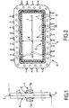
- a vertical oven H of a heat treatment line for a metal strip 1, in particular a steel strip, which can be seen continuously, at constant or variable speed, can be seen diagrammatically.
- the strip 1 moves vertically between two rollers respectively lower 2 and upper 3. This example is not limiting, the strip 1 could run horizontally in a horizontal oven.
- the furnace generally has a prismatic shape with a rectangular cross section and its internal volume is isolated from the external atmosphere.
- the composition of the gas mixture inside the oven can vary depending on the areas considered.
- This gas mixture comprises a relatively high proportion of hydrogen favorable to heat exchange.
- the furnace H comprises at least one heating section 4 equipped, on each side of the strip 1, with a half-inductor with transverse or pseudo-transverse flow 5a, 5b.
- a couple of half inductors constitutes a heating inductor.
- a thermal insulation screen E transparent to the magnetic flux is provided to thermally protect the inductors from the heated product constituted by the strip 1.
- the screen E comprises a support 6 formed of an electrically insulating material and, in particular, gas tight.
- Support 6 is advantageously made of composite material with epoxy resin or the like.
- the minimum dimension k ( Fig.2 ) the space between opposite faces of the screen E, in the direction orthogonal to the strip 1, is imposed by considerations aimed at avoiding any contact between the strip and the internal surface of the screen.
- This dimension k can be of the order of twenty centimeters.
- the internal faces of the support 6 support and maintain, by means of fixing not shown, a matrix B of blocks 7 made of thermally insulating material, in particular ceramic, and a plurality of tubes 8 cooled by circulation of a fluid, generally of the 'water.
- the tubes 8 are generally metallic, but could be made of another material, for example glass completely transparent to the magnetic field. The tubes 8 are trapped in the matrix of blocks 7 and protected against the direct radiation of the strip 1.
- the tubes 8 preferably consist of straight segments. According to the example of Fig.3 the tubes 8 are segments of a continuous coil, obtained by successive bending at 180 ° in opposite directions of a tube. A coolant inlet and outlet is provided for each coil. Several coils constituting successive panels can be juxtaposed against the internal wall of the support 6.
- the internal diameter of the tubes 8 is of the order of eight to ten millimeters.
- Boxes 7, as visible on Fig. 2 and 4 are constituted by substantially rectangular parallelepipedal blocks, the two longitudinal faces of which have recesses 7a, 7b in the form of cylindrical portions suitable for conforming to the contour of two successive tubes 8.
- the blocks 7 can thus be engaged between two straight tubes 8.
- the blocks 7 are pressed against each other in the longitudinal direction of the tubes 8.
- a reduced space 9 ( Fig. 4 ) can remain transversely between two neighboring pavers 7.
- the front face 7c of the blocks 7 is that directly exposed to the thermal radiation of the strip 1.
- the rear face 7d of the blocks, which is the side furthest from the strip 1, is at a temperature much lower than that of the face 7c due to the thermal resistance opposed by the block 7 and the heat dissipation provided by the tubes 8 and the cooling fluid.
- the inductors For maximum energy efficiency of heating band 1 by electromagnetic induction with transverse or pseudo-transverse flux, it is desirable to place the inductors as close as possible to the strip 1. When the processing temperature of the strip 1 increases, the support 6 may be subjected to too high a temperature.
- means 10 are provided on the rear face 7d of the blocks. heat conductors arranged to intercept the heat flow Q passing through the blocks 7. These conductive means 10 are in thermal connection with the cooled tubes 8 to evacuate the heat flow Q towards the tubes and towards the coolant circulating in the tubes .
- the conductive means 10 are equipped, as illustrated in Fig.6 , means 11 for preventing or reducing the formation of induced currents generated by the transverse alternating electromagnetic flux.
- the conductive means 10 consist of a metal screen S of thickness j ( Fig.4 ) reduced, in particular less than five millimeters.
- the screen S covers most of the rear faces 7d of the blocks.
- the metallic screen S is constituted by a set of metallic fins 12 distinct from each other.
- Each tube 8 is associated with metal fins 12 covering the rear face 7d of the blocks, each fin being in thermal contact with the associated tube 8 cooled.
- the terms “drain” or “heat puller” could be used as synonyms instead of the term “fin”.
- Each fin 12 is formed by a metal strip preferably extending along the entire length of the tube 8.
- the strip has a projecting central longitudinal part 12a engaged in a free space 13 between the rear edges of two successive blocks 7.
- the central part 12a comes into contact with the wall of the tube 8 to which it is preferably welded.
- the metal strip extends on either side of the central part 12a symmetrically, or asymmetrically, along blades 12b, 12c arriving substantially at the half-width of each block 7. Such an arrangement makes it possible to limit the length of the heat evacuation path to the tube 8 at substantially half the width of a block 7.
- edges of the blades 12b, 12c of two successive fins are separated by a width interval m ( Fig.4 ) reduced, in particular less than five millimeters, and preferably less than two millimeters.
- the rear face 7d of each block is thus almost entirely covered by fins 12.
- the cross section of the heat shield has a substantially rectangular closed contour.
- the heat shield can be formed, on each side of the strip, by a plate having several layers (insulating blocks, cooled tubes, conductive means).
- the cross section of the screen would be a straight segment, as shown in Fig.4 .
- a plate-shaped heat shield, in accordance with the invention, is particularly suitable for installations such as those referred to in patent applications FR 05 06462 and FR 05 06463, filed on June 24, 2005 by the same CELES depositing company.
- the central part 12a of the fin has the shape of a dome turning its convexity towards the tube 8 and comprising oblong openings 14 for welding.
- the central projecting part 12a1 has a concavity forming a cradle to match the opposite part of the tube 8 and ensure a larger contact surface for the transmission of heat.
- the fins can be produced by slots made in an assembly [tube 8 - metal screen S] extruded or drawn in one piece.
- the means 11 for preventing, or reducing, the formation of induced currents generated by the magnetic flux preferably comprise slots 15, formed in the fins 12.
- the slots are oriented mainly transversely to the longitudinal direction of the fins, as illustrated in Fig.6 , but they can also be tilted.
- the heat shield is obtained when the induced currents are extremely low.
- fins are provided whose surface perpendicular to the magnetic field is sufficiently reduced.
- a good result is obtained by reducing the pitch of the slots, by playing on the width of the slot, in particular on the thickness of a saw cut constituting the slot, and / or by playing on the width of the fin and l 'thickness.
- the width of the slot is 0.5 mm
- the width of the fin between two slots is adapted to the electrical losses of the currents induced in this fin.
- the fins can be produced by sections of metal wire.
- the sections of wire are oriented transversely, radially or obliquely, with respect to the cooling tubes 8, and are fixed, in particular welded to the tubes 8, the assembly resembling a comb whose teeth are formed by the sections of wire.
- the wire diameter can be 1mm with a gap between each wire of 0.3mm, this gap constituting the slot 15.
- the fin 12 top view as illustrated in Fig. 6 , has a shape reminiscent of a fishbone.
- the tubes 8 and / or the fins 12 are advantageously made of stainless steel.
- the tubes 8 and / or the fins 12 are made of bronze or copper, other metals also being possible.
- the transverse alternating magnetic field makes it possible to heat the strip 1 which radiates heat towards the surfaces which surround this strip.
- the heat flow Q which crosses the blocks 7 to reach the rear face 7d is intercepted for the most part by the fins 12 and discharged towards the tubes 8 and the cooling fluid.
- the support 6 is more protected against overheating which would be due to this flow Q.
- the invention makes it possible, without substantially increasing the thickness of the thermal screen E and without modifying the spacing of the tubes 8, to ensure effective thermal protection of the support 6 for high strip temperatures 1, in particular of 1150 ° C. .
- strip 1 Although the description has been made with respect to a strip 1, the invention applies to other types of metal products, in particular steel, copper, aluminum wires or plates.
- the product may or may not scroll.
Landscapes
- Engineering & Computer Science (AREA)
- Chemical & Material Sciences (AREA)
- Mechanical Engineering (AREA)
- Physics & Mathematics (AREA)
- Materials Engineering (AREA)
- Crystallography & Structural Chemistry (AREA)
- Thermal Sciences (AREA)
- Metallurgy (AREA)
- Organic Chemistry (AREA)
- Electromagnetism (AREA)
- General Engineering & Computer Science (AREA)
- General Induction Heating (AREA)
- Furnace Details (AREA)
- Heat Treatment Of Strip Materials And Filament Materials (AREA)
- Cooling Or The Like Of Electrical Apparatus (AREA)
Claims (15)
- Magnetstromdurchlässige Wärmeabschirmung, die dazu bestimmt ist, einen elektromagnetischen Induktor mit transversalem oder pseudo-transversalem Feld vor der Strahlung eines erhitzten Produkts (1) zu isolieren, wobei die Wärmeabschirmung aus einer Matrix von Blöcken (7) aus wärmeisolierendem Material und einer Vielzahl von Rohren (8) besteht, die durch Umlauf eines Fluids gekühlt werden, wobei diese Rohre in der Matrix von Blöcken eingeschlossen sind, wobei die Rohre und Blöcke auf einem Träger (6) gehalten werden, dadurch gekennzeichnet, dass sie Schirme (10) aus wärmeleitendem Material umfasst, die so angeordnet sind, dass sie den durch die Blöcke strömenden Wärmestrom abfangen, wobei die Schirme aus wärmeleitendem Material zwischen der Rückseite der Blöcke und dem Träger (6) angeordnet sind, und diese Schirme aus leitendem Material in thermischer Verbindung mit den gekühlten Rohren (8) stehen, um den Wärmestrom zu den Rohren abzuleiten.
- Wärmeabschirmung nach Anspruch 1, bei der die Schirme (10) aus wärmeleitendem Material mit Mitteln (11) zur Verhinderung oder Verringerung der Bildung von Strömen versehen sind, die durch den magnetischen Fluss induziert werden.
- Wärmeabschirmung nach Anspruch 1 oder 2, bei der die Schirme (10) aus wärmeleitendem Material durch eine Metallabschirmung (S) gebildet werden, der in thermischer Verbindung mit den gekühlten Rohren (8) steht.
- Wärmeabschirmung nach Anspruch 3, bei der die Metallabschirmung (S) aus Metallrippen (12) besteht, die sich hinter den Blöcken erstrecken, wobei jede Rippe (12) in thermischem Kontakt mit einem gekühlten Rohr (8) steht.
- Wärmeabschirmung nach Anspruch 4, bei der die Rippen aus Drahtabschnitten bestehen, die auf den Kühlrohren befestigt sind.
- Wärmeabschirmung nach einem der vorhergehenden Ansprüche, bei der die Mittel (11) zur Verhinderung oder Verringerung der Bildung von Induktionsströmen, die durch den magnetischen Fluss erzeugt werden, Schlitze (15) umfassen, die in den Schirmen aus leitfähigem Material (10) ausgebildet sind.
- Wärmeabschirmung nach Anspruch 6, bei der die Schlitze (15) quer zur Längsrichtung der Rohre (8) ausgerichtet sind.
- Wärmeabschirmung nach Anspruch 4 und Anspruch 6 oder 7, bei der die Schlitze (15) bis zu den Längskanten der Metallabschirmung geführt werden und in der Nähe des Mittelteils geschlossen sind.
- Wärmeabschirmung nach Anspruch 4, bei der sich jede Rippe (12) zu beiden Seiten eines Rohres (8) erstreckt.
- Wärmeabschirmung nach Anspruch 9, bei der sich jede Rippe (12) auf jeder Seite eines Rohres (8) im Wesentlichen bis zur Hälfte des Zwischenraums zwischen zwei benachbarten Rohren (8) erstreckt.
- Wärmeabschirmung nach einem der Ansprüche 4 bis 10, bei dem jede Rippe (12) an ein Rohr (8) geschweißt ist.
- Wärmeabschirmung nach einem der Ansprüche 4 bis 10, bei dem die Rippen durch Schlitze gebildet werden, die in einer, in einem Stück stranggegossenen oder gezogenen Rohr-Metallabschirmungs-Einheit ausgebildet werden.
- Wärmeabschirmung nach Anspruch 4, bei dem der an das Rohr angrenzende Rippenbereich die Form einer Bettung (12a1) hat, die der Form eines Teils der Rohrkontur entspricht.
- Wärmeabschirmung nach Anspruch 4, bei der die Rippen (12) in der gesamten Länge der Rohre im Bereich des Induktors vorgesehen sind, der vor dem Wärmefluss zu schützen ist.
- Wärmebehandlungsanlage, insbesondere ein Ofen, die einen elektromagnetischen Induktor mit einem transversalen oder pseudo-transversalen Feld zum Erhitzen eines Produkts umfasst, dadurch gekennzeichnet, dass sie zum Schutz des Induktors vor der Wärmestrahlung des erhitzten Produkts mindestens eine Wärmeabschirmung (E) nach einem der vorhergehenden Ansprüche umfasst.
Applications Claiming Priority (2)
| Application Number | Priority Date | Filing Date | Title |
|---|---|---|---|
| FR0600053A FR2895871B1 (fr) | 2006-01-04 | 2006-01-04 | Ecran d'isolation thermique pour isoler un inducteur electromagnetique, et installation de traitement thermique comportant un tel ecran |
| PCT/FR2006/002879 WO2007077363A2 (fr) | 2006-01-04 | 2006-12-26 | Ecran d'isolation thermique pour isoler un inducteur electromagnetique, et installation de traitement thermique comportant un tel ecran. |
Publications (2)
| Publication Number | Publication Date |
|---|---|
| EP1969149A2 EP1969149A2 (de) | 2008-09-17 |
| EP1969149B1 true EP1969149B1 (de) | 2020-01-29 |
Family
ID=37081459
Family Applications (1)
| Application Number | Title | Priority Date | Filing Date |
|---|---|---|---|
| EP06847143.2A Active EP1969149B1 (de) | 2006-01-04 | 2006-12-26 | Thermische isolierende schirm zum schützen eines elektromagnetischen induktors und ausrüstung von thermischen behandlung versehen mit solchem schirm |
Country Status (10)
| Country | Link |
|---|---|
| US (1) | US20090194258A1 (de) |
| EP (1) | EP1969149B1 (de) |
| JP (1) | JP5290768B2 (de) |
| CN (1) | CN101484594B (de) |
| BR (1) | BRPI0620872A2 (de) |
| ES (1) | ES2777839T3 (de) |
| FR (1) | FR2895871B1 (de) |
| RU (1) | RU2416064C2 (de) |
| WO (1) | WO2007077363A2 (de) |
| ZA (1) | ZA200805523B (de) |
Families Citing this family (3)
| Publication number | Priority date | Publication date | Assignee | Title |
|---|---|---|---|---|
| GB0812864D0 (en) | 2008-07-15 | 2008-08-20 | Cxr Ltd | Coolign anode |
| CN109579515A (zh) * | 2018-11-26 | 2019-04-05 | 太原开元智能装备有限公司 | 一种外热式真空连续烧结炉 |
| IT201900006433A1 (it) * | 2019-04-29 | 2020-10-29 | Rotelec Sa | Apparato di riscaldamento di prodotti metallici |
Citations (1)
| Publication number | Priority date | Publication date | Assignee | Title |
|---|---|---|---|---|
| US6404799B1 (en) * | 1999-02-03 | 2002-06-11 | Nippon Steel Corporation | Water-cooling panel for furnace wall and furnace cover of arc furnace |
Family Cites Families (11)
| Publication number | Priority date | Publication date | Assignee | Title |
|---|---|---|---|---|
| US3004328A (en) * | 1956-02-29 | 1961-10-17 | Foster Wheeler Corp | Fin and tube assembly and method of bonding same |
| GB2119491B (en) * | 1981-11-16 | 1985-01-30 | Kudinov Gennady A | Cooling plate for metallurgical furnaces |
| GB8404767D0 (en) * | 1984-02-23 | 1984-03-28 | Davy Mckee Poole | Transverse flux induction heaters |
| CN2098779U (zh) * | 1991-08-04 | 1992-03-11 | 吴志光 | 电磁热管 |
| JP3116730B2 (ja) * | 1994-07-21 | 2000-12-11 | 三菱電機株式会社 | 電磁誘導加熱装置の断熱部材 |
| FR2752134B1 (fr) * | 1996-08-02 | 2003-12-26 | Selas Sa | Dispositif de chauffage par induction et installation de traitement thermique en continu comportant un tel dispositif |
| JP3479868B2 (ja) * | 1997-12-29 | 2003-12-15 | 北芝電機株式会社 | 誘導加熱装置 |
| SE515593C2 (sv) * | 1999-03-01 | 2001-09-03 | Avesta Sheffield Ab | Apparat för värmning av ett metallband |
| FR2821925B1 (fr) * | 2001-03-06 | 2003-05-16 | Celes | Enceinte d'etancheite au gaz et au vide d'isolation thermique destinee a un dispositif de chauffage par induction |
| CN2647868Y (zh) * | 2003-08-27 | 2004-10-13 | 黄石山力涂镀层工程技术有限公司 | 带钢连续热处理炉电辐射管加热装置 |
| CN2645396Y (zh) * | 2003-09-09 | 2004-09-29 | 王文生 | 一种电磁感应热管 |
-
2006
- 2006-01-04 FR FR0600053A patent/FR2895871B1/fr not_active Expired - Fee Related
- 2006-12-26 WO PCT/FR2006/002879 patent/WO2007077363A2/fr not_active Ceased
- 2006-12-26 RU RU2008127076/02A patent/RU2416064C2/ru active
- 2006-12-26 JP JP2008549035A patent/JP5290768B2/ja active Active
- 2006-12-26 CN CN2006800504204A patent/CN101484594B/zh active Active
- 2006-12-26 EP EP06847143.2A patent/EP1969149B1/de active Active
- 2006-12-26 BR BRPI0620872-0A patent/BRPI0620872A2/pt not_active Application Discontinuation
- 2006-12-26 ES ES06847143T patent/ES2777839T3/es active Active
- 2006-12-26 US US12/097,416 patent/US20090194258A1/en not_active Abandoned
-
2008
- 2008-06-24 ZA ZA200805523A patent/ZA200805523B/xx unknown
Patent Citations (1)
| Publication number | Priority date | Publication date | Assignee | Title |
|---|---|---|---|---|
| US6404799B1 (en) * | 1999-02-03 | 2002-06-11 | Nippon Steel Corporation | Water-cooling panel for furnace wall and furnace cover of arc furnace |
Also Published As
| Publication number | Publication date |
|---|---|
| CN101484594A (zh) | 2009-07-15 |
| ZA200805523B (en) | 2009-04-29 |
| CN101484594B (zh) | 2011-08-10 |
| FR2895871A1 (fr) | 2007-07-06 |
| RU2008127076A (ru) | 2010-01-10 |
| WO2007077363A2 (fr) | 2007-07-12 |
| ES2777839T3 (es) | 2020-08-06 |
| JP5290768B2 (ja) | 2013-09-18 |
| RU2416064C2 (ru) | 2011-04-10 |
| US20090194258A1 (en) | 2009-08-06 |
| JP2009522740A (ja) | 2009-06-11 |
| FR2895871B1 (fr) | 2008-02-29 |
| BRPI0620872A2 (pt) | 2011-11-29 |
| WO2007077363A3 (fr) | 2007-08-23 |
| EP1969149A2 (de) | 2008-09-17 |
Similar Documents
| Publication | Publication Date | Title |
|---|---|---|
| EP1349431B1 (de) | Vakuum- und gasdichter Behälter zur thermischen Isolierung von Induktionsheizeinrichtungen | |
| FR2853378A1 (fr) | Plaquettes de frein a disque ventilees | |
| EP1969149B1 (de) | Thermische isolierende schirm zum schützen eines elektromagnetischen induktors und ausrüstung von thermischen behandlung versehen mit solchem schirm | |
| EP1703611A1 (de) | Elektrische Durchführung für supraleitendes Element | |
| FR2487620A1 (fr) | Dispositif chauffant electrique pour une table de cuisson en vitroceramique | |
| WO2021019139A1 (fr) | Capot pour vehicule, en particulier pour vehicule supersonique ou hypersonique | |
| EP0020215B1 (de) | Induktionswiedererwärmungsofen mit Wanderfeld | |
| FR2901658A1 (fr) | Element metallique dissipant une energie thermique, traverse par un flux d'air et par un courant electrique | |
| FR2479345A1 (fr) | Cryopompe | |
| EP0225835B1 (de) | Elektrische Heizkabel | |
| EP1364425B1 (de) | Keramisches mikrowellenfenster | |
| EP2713374A1 (de) | Hochleistung feuerbeständiges vieladriges Kabel | |
| EP3518641B1 (de) | Kühlsystem einer elektronischen vorrichtung, und methode zum zusammenbau | |
| EP0280940B1 (de) | Divertor-Kollektor eines Tokamak-Nuklearfusionsreaktors | |
| EP1900255B8 (de) | Induktionsofen zum behandeln von elektrisch leitfähigen streifen, blättern, platten und feldwicklung dafür | |
| WO2006136702A1 (fr) | Four a induction pour traiter des bandes, toles, plaques, en materiau conducteur de l'electricite, et inducteur pour un tel four. | |
| FR2972890A1 (fr) | Systeme inductif pouvant servir de creuset froid | |
| FR2867608A1 (fr) | Refroidisseur pour composant electronique de puissance | |
| BE1014988A7 (fr) | Ecran de protection. | |
| EP1700515B1 (de) | Elektrode zum erzeugen eines dielektrische-barriere-entladungsplasmas | |
| FR3151082A3 (fr) | Procédé de fabrication d’un échangeur comprenant des passages dotés d’au moins un organe de support et échangeur fabriqué par un tel procédé | |
| EP3166177B1 (de) | Mikrowellenfenster | |
| EP3266278B1 (de) | Heizkabel mit gerichtetem wärmefluss | |
| EP2994351B1 (de) | Kabelkanal für ein fahrzeugantriebssystem | |
| FR2859575A1 (fr) | Connecteur electrique pour raccorder un conducteur electrique avec un composant electrique |
Legal Events
| Date | Code | Title | Description |
|---|---|---|---|
| PUAI | Public reference made under article 153(3) epc to a published international application that has entered the european phase |
Free format text: ORIGINAL CODE: 0009012 |
|
| 17P | Request for examination filed |
Effective date: 20080619 |
|
| AK | Designated contracting states |
Kind code of ref document: A2 Designated state(s): BE DE ES FI FR IT |
|
| RAP1 | Party data changed (applicant data changed or rights of an application transferred) |
Owner name: FIVES CELES |
|
| RBV | Designated contracting states (corrected) |
Designated state(s): BE DE ES FI FR IT |
|
| 17Q | First examination report despatched |
Effective date: 20090211 |
|
| DAX | Request for extension of the european patent (deleted) | ||
| GRAP | Despatch of communication of intention to grant a patent |
Free format text: ORIGINAL CODE: EPIDOSNIGR1 |
|
| INTG | Intention to grant announced |
Effective date: 20190731 |
|
| GRAS | Grant fee paid |
Free format text: ORIGINAL CODE: EPIDOSNIGR3 |
|
| GRAA | (expected) grant |
Free format text: ORIGINAL CODE: 0009210 |
|
| AK | Designated contracting states |
Kind code of ref document: B1 Designated state(s): BE DE ES FI FR IT |
|
| REG | Reference to a national code |
Ref country code: DE Ref legal event code: R096 Ref document number: 602006059102 Country of ref document: DE |
|
| PG25 | Lapsed in a contracting state [announced via postgrant information from national office to epo] |
Ref country code: FI Free format text: LAPSE BECAUSE OF FAILURE TO SUBMIT A TRANSLATION OF THE DESCRIPTION OR TO PAY THE FEE WITHIN THE PRESCRIBED TIME-LIMIT Effective date: 20200129 |
|
| REG | Reference to a national code |
Ref country code: ES Ref legal event code: FG2A Ref document number: 2777839 Country of ref document: ES Kind code of ref document: T3 Effective date: 20200806 |
|
| REG | Reference to a national code |
Ref country code: DE Ref legal event code: R097 Ref document number: 602006059102 Country of ref document: DE |
|
| PLBE | No opposition filed within time limit |
Free format text: ORIGINAL CODE: 0009261 |
|
| STAA | Information on the status of an ep patent application or granted ep patent |
Free format text: STATUS: NO OPPOSITION FILED WITHIN TIME LIMIT |
|
| 26N | No opposition filed |
Effective date: 20201030 |
|
| PGFP | Annual fee paid to national office [announced via postgrant information from national office to epo] |
Ref country code: DE Payment date: 20251126 Year of fee payment: 20 |
|
| PGFP | Annual fee paid to national office [announced via postgrant information from national office to epo] |
Ref country code: IT Payment date: 20251119 Year of fee payment: 20 |
|
| PGFP | Annual fee paid to national office [announced via postgrant information from national office to epo] |
Ref country code: FR Payment date: 20251119 Year of fee payment: 20 |
|
| PGFP | Annual fee paid to national office [announced via postgrant information from national office to epo] |
Ref country code: BE Payment date: 20251119 Year of fee payment: 20 |
|
| PGFP | Annual fee paid to national office [announced via postgrant information from national office to epo] |
Ref country code: ES Payment date: 20260102 Year of fee payment: 20 |