EP0280940B1 - Divertor-Kollektor eines Tokamak-Nuklearfusionsreaktors - Google Patents
Divertor-Kollektor eines Tokamak-Nuklearfusionsreaktors Download PDFInfo
- Publication number
- EP0280940B1 EP0280940B1 EP88102002A EP88102002A EP0280940B1 EP 0280940 B1 EP0280940 B1 EP 0280940B1 EP 88102002 A EP88102002 A EP 88102002A EP 88102002 A EP88102002 A EP 88102002A EP 0280940 B1 EP0280940 B1 EP 0280940B1
- Authority
- EP
- European Patent Office
- Prior art keywords
- fibers
- diverter
- plate
- collector according
- collector
- Prior art date
- Legal status (The legal status is an assumption and is not a legal conclusion. Google has not performed a legal analysis and makes no representation as to the accuracy of the status listed.)
- Expired - Lifetime
Links
- 230000004927 fusion Effects 0.000 title claims description 11
- 239000000835 fiber Substances 0.000 claims description 63
- RYGMFSIKBFXOCR-UHFFFAOYSA-N Copper Chemical compound [Cu] RYGMFSIKBFXOCR-UHFFFAOYSA-N 0.000 claims description 23
- 229910052802 copper Inorganic materials 0.000 claims description 23
- 239000010949 copper Substances 0.000 claims description 23
- 150000002500 ions Chemical class 0.000 claims description 18
- 239000000463 material Substances 0.000 claims description 17
- 230000017525 heat dissipation Effects 0.000 claims description 14
- OKTJSMMVPCPJKN-UHFFFAOYSA-N Carbon Chemical compound [C] OKTJSMMVPCPJKN-UHFFFAOYSA-N 0.000 claims description 10
- 229910002804 graphite Inorganic materials 0.000 claims description 10
- 239000010439 graphite Substances 0.000 claims description 10
- WFKWXMTUELFFGS-UHFFFAOYSA-N tungsten Chemical compound [W] WFKWXMTUELFFGS-UHFFFAOYSA-N 0.000 claims description 8
- 229910052721 tungsten Inorganic materials 0.000 claims description 8
- 239000010937 tungsten Substances 0.000 claims description 8
- 239000011819 refractory material Substances 0.000 claims description 7
- 239000007788 liquid Substances 0.000 claims description 6
- 238000004519 manufacturing process Methods 0.000 claims description 6
- 230000004907 flux Effects 0.000 claims description 4
- 238000000034 method Methods 0.000 claims description 4
- FRWYFWZENXDZMU-UHFFFAOYSA-N 2-iodoquinoline Chemical compound C1=CC=CC2=NC(I)=CC=C21 FRWYFWZENXDZMU-UHFFFAOYSA-N 0.000 claims description 3
- ZSLUVFAKFWKJRC-IGMARMGPSA-N 232Th Chemical compound [232Th] ZSLUVFAKFWKJRC-IGMARMGPSA-N 0.000 claims description 3
- XUIMIQQOPSSXEZ-UHFFFAOYSA-N Silicon Chemical compound [Si] XUIMIQQOPSSXEZ-UHFFFAOYSA-N 0.000 claims description 3
- 229910052776 Thorium Inorganic materials 0.000 claims description 3
- 229910001080 W alloy Inorganic materials 0.000 claims description 3
- 229910045601 alloy Inorganic materials 0.000 claims description 3
- 239000000956 alloy Substances 0.000 claims description 3
- 229910052782 aluminium Inorganic materials 0.000 claims description 3
- XAGFODPZIPBFFR-UHFFFAOYSA-N aluminium Chemical compound [Al] XAGFODPZIPBFFR-UHFFFAOYSA-N 0.000 claims description 3
- 229910052790 beryllium Inorganic materials 0.000 claims description 3
- ATBAMAFKBVZNFJ-UHFFFAOYSA-N beryllium atom Chemical compound [Be] ATBAMAFKBVZNFJ-UHFFFAOYSA-N 0.000 claims description 3
- LTPBRCUWZOMYOC-UHFFFAOYSA-N beryllium oxide Inorganic materials O=[Be] LTPBRCUWZOMYOC-UHFFFAOYSA-N 0.000 claims description 3
- 238000002513 implantation Methods 0.000 claims description 3
- 229910052702 rhenium Inorganic materials 0.000 claims description 3
- WUAPFZMCVAUBPE-UHFFFAOYSA-N rhenium atom Chemical compound [Re] WUAPFZMCVAUBPE-UHFFFAOYSA-N 0.000 claims description 3
- 229910052710 silicon Inorganic materials 0.000 claims description 3
- 239000010703 silicon Substances 0.000 claims description 3
- HBMJWWWQQXIZIP-UHFFFAOYSA-N silicon carbide Chemical compound [Si+]#[C-] HBMJWWWQQXIZIP-UHFFFAOYSA-N 0.000 claims description 3
- 229910010271 silicon carbide Inorganic materials 0.000 claims description 3
- 229910052715 tantalum Inorganic materials 0.000 claims description 3
- GUVRBAGPIYLISA-UHFFFAOYSA-N tantalum atom Chemical compound [Ta] GUVRBAGPIYLISA-UHFFFAOYSA-N 0.000 claims description 3
- 239000000919 ceramic Substances 0.000 claims description 2
- 239000004411 aluminium Substances 0.000 claims 1
- 239000007791 liquid phase Substances 0.000 claims 1
- -1 molbybdenum Chemical compound 0.000 claims 1
- 239000010410 layer Substances 0.000 description 9
- 230000003628 erosive effect Effects 0.000 description 5
- 239000011159 matrix material Substances 0.000 description 4
- 230000001681 protective effect Effects 0.000 description 4
- WHXSMMKQMYFTQS-UHFFFAOYSA-N Lithium Chemical compound [Li] WHXSMMKQMYFTQS-UHFFFAOYSA-N 0.000 description 3
- 230000008901 benefit Effects 0.000 description 3
- 239000002131 composite material Substances 0.000 description 3
- 238000001816 cooling Methods 0.000 description 3
- 230000007423 decrease Effects 0.000 description 3
- 229910052744 lithium Inorganic materials 0.000 description 3
- 239000002245 particle Substances 0.000 description 3
- 238000001953 recrystallisation Methods 0.000 description 3
- 239000011347 resin Substances 0.000 description 3
- 229920005989 resin Polymers 0.000 description 3
- ZOKXTWBITQBERF-UHFFFAOYSA-N Molybdenum Chemical compound [Mo] ZOKXTWBITQBERF-UHFFFAOYSA-N 0.000 description 2
- 229910000756 V alloy Inorganic materials 0.000 description 2
- 229910001093 Zr alloy Inorganic materials 0.000 description 2
- 230000005540 biological transmission Effects 0.000 description 2
- 238000006243 chemical reaction Methods 0.000 description 2
- 230000007547 defect Effects 0.000 description 2
- 229910052750 molybdenum Inorganic materials 0.000 description 2
- 239000011733 molybdenum Substances 0.000 description 2
- 239000011241 protective layer Substances 0.000 description 2
- 230000005855 radiation Effects 0.000 description 2
- 230000008646 thermal stress Effects 0.000 description 2
- 229920000049 Carbon (fiber) Polymers 0.000 description 1
- QCWXUUIWCKQGHC-UHFFFAOYSA-N Zirconium Chemical compound [Zr] QCWXUUIWCKQGHC-UHFFFAOYSA-N 0.000 description 1
- 230000004888 barrier function Effects 0.000 description 1
- 238000005219 brazing Methods 0.000 description 1
- 239000004917 carbon fiber Substances 0.000 description 1
- 238000003763 carbonization Methods 0.000 description 1
- 230000001143 conditioned effect Effects 0.000 description 1
- 239000004020 conductor Substances 0.000 description 1
- 238000011109 contamination Methods 0.000 description 1
- 230000008878 coupling Effects 0.000 description 1
- 238000010168 coupling process Methods 0.000 description 1
- 238000005859 coupling reaction Methods 0.000 description 1
- 239000006185 dispersion Substances 0.000 description 1
- 238000009826 distribution Methods 0.000 description 1
- 238000005516 engineering process Methods 0.000 description 1
- 239000000284 extract Substances 0.000 description 1
- 239000002657 fibrous material Substances 0.000 description 1
- 239000007943 implant Substances 0.000 description 1
- 230000008595 infiltration Effects 0.000 description 1
- 238000001764 infiltration Methods 0.000 description 1
- 238000010884 ion-beam technique Methods 0.000 description 1
- 229910001338 liquidmetal Inorganic materials 0.000 description 1
- WHXSMMKQMYFTQS-BKFZFHPZSA-N lithium-12 Chemical compound [12Li] WHXSMMKQMYFTQS-BKFZFHPZSA-N 0.000 description 1
- 230000007246 mechanism Effects 0.000 description 1
- 238000002844 melting Methods 0.000 description 1
- 230000008018 melting Effects 0.000 description 1
- 230000000704 physical effect Effects 0.000 description 1
- 238000006116 polymerization reaction Methods 0.000 description 1
- 230000008569 process Effects 0.000 description 1
- 238000005086 pumping Methods 0.000 description 1
- 230000000717 retained effect Effects 0.000 description 1
- 238000005245 sintering Methods 0.000 description 1
- 239000007787 solid Substances 0.000 description 1
- 230000007480 spreading Effects 0.000 description 1
- 238000003892 spreading Methods 0.000 description 1
- 230000035882 stress Effects 0.000 description 1
- 229920001187 thermosetting polymer Polymers 0.000 description 1
- LEONUFNNVUYDNQ-UHFFFAOYSA-N vanadium atom Chemical compound [V] LEONUFNNVUYDNQ-UHFFFAOYSA-N 0.000 description 1
Images

Classifications
-
- G—PHYSICS
- G21—NUCLEAR PHYSICS; NUCLEAR ENGINEERING
- G21B—FUSION REACTORS
- G21B1/00—Thermonuclear fusion reactors
-
- F—MECHANICAL ENGINEERING; LIGHTING; HEATING; WEAPONS; BLASTING
- F16—ENGINEERING ELEMENTS AND UNITS; GENERAL MEASURES FOR PRODUCING AND MAINTAINING EFFECTIVE FUNCTIONING OF MACHINES OR INSTALLATIONS; THERMAL INSULATION IN GENERAL
- F16B—DEVICES FOR FASTENING OR SECURING CONSTRUCTIONAL ELEMENTS OR MACHINE PARTS TOGETHER, e.g. NAILS, BOLTS, CIRCLIPS, CLAMPS, CLIPS OR WEDGES; JOINTS OR JOINTING
- F16B5/00—Joining sheets or plates, e.g. panels, to one another or to strips or bars parallel to them
-
- G—PHYSICS
- G21—NUCLEAR PHYSICS; NUCLEAR ENGINEERING
- G21B—FUSION REACTORS
- G21B1/00—Thermonuclear fusion reactors
- G21B1/11—Details
-
- F—MECHANICAL ENGINEERING; LIGHTING; HEATING; WEAPONS; BLASTING
- F16—ENGINEERING ELEMENTS AND UNITS; GENERAL MEASURES FOR PRODUCING AND MAINTAINING EFFECTIVE FUNCTIONING OF MACHINES OR INSTALLATIONS; THERMAL INSULATION IN GENERAL
- F16B—DEVICES FOR FASTENING OR SECURING CONSTRUCTIONAL ELEMENTS OR MACHINE PARTS TOGETHER, e.g. NAILS, BOLTS, CIRCLIPS, CLAMPS, CLIPS OR WEDGES; JOINTS OR JOINTING
- F16B2200/00—Constructional details of connections not covered for in other groups of this subclass
- F16B2200/97—Constructional details of connections not covered for in other groups of this subclass having differing thermal expansion coefficients
-
- F—MECHANICAL ENGINEERING; LIGHTING; HEATING; WEAPONS; BLASTING
- F28—HEAT EXCHANGE IN GENERAL
- F28D—HEAT-EXCHANGE APPARATUS, NOT PROVIDED FOR IN ANOTHER SUBCLASS, IN WHICH THE HEAT-EXCHANGE MEDIA DO NOT COME INTO DIRECT CONTACT
- F28D21/00—Heat-exchange apparatus not covered by any of the groups F28D1/00 - F28D20/00
- F28D2021/0019—Other heat exchangers for particular applications; Heat exchange systems not otherwise provided for
- F28D2021/0077—Other heat exchangers for particular applications; Heat exchange systems not otherwise provided for for tempering, e.g. with cooling or heating circuits for temperature control of elements
- F28D2021/0078—Other heat exchangers for particular applications; Heat exchange systems not otherwise provided for for tempering, e.g. with cooling or heating circuits for temperature control of elements in the form of cooling walls
-
- F—MECHANICAL ENGINEERING; LIGHTING; HEATING; WEAPONS; BLASTING
- F28—HEAT EXCHANGE IN GENERAL
- F28F—DETAILS OF HEAT-EXCHANGE AND HEAT-TRANSFER APPARATUS, OF GENERAL APPLICATION
- F28F2265/00—Safety or protection arrangements; Arrangements for preventing malfunction
- F28F2265/10—Safety or protection arrangements; Arrangements for preventing malfunction for preventing overheating, e.g. heat shields
-
- Y—GENERAL TAGGING OF NEW TECHNOLOGICAL DEVELOPMENTS; GENERAL TAGGING OF CROSS-SECTIONAL TECHNOLOGIES SPANNING OVER SEVERAL SECTIONS OF THE IPC; TECHNICAL SUBJECTS COVERED BY FORMER USPC CROSS-REFERENCE ART COLLECTIONS [XRACs] AND DIGESTS
- Y02—TECHNOLOGIES OR APPLICATIONS FOR MITIGATION OR ADAPTATION AGAINST CLIMATE CHANGE
- Y02E—REDUCTION OF GREENHOUSE GAS [GHG] EMISSIONS, RELATED TO ENERGY GENERATION, TRANSMISSION OR DISTRIBUTION
- Y02E30/00—Energy generation of nuclear origin
- Y02E30/10—Nuclear fusion reactors
Definitions
- the invention relates to a receiver-collector of a Tokamak type nuclear fusion reactor, this receiver-collector being composed of a heat dissipation plate and an ion protection layer which covers and protects said plate. against the ion flow prevailing in the reactor.
- the main function of a Tokamak-type reactor manifold is to extract particles and thermal energy from the plasma in order to keep its contamination low and protect the first wall from excessive heat and excessive particle flow during the active phase.
- an "open" configuration of the magnetic lines is provided at at least one end of the torus section.
- the ions which cross a dividing line thus created are no longer trapped and are intercepted by the divertor-collector where they are neutralized and extracted by pumping.
- the manifold is located either at the top or bottom of the toroidal plasma chamber, or in two places at the same time, and is designed to dissipate most of the thermal energy produced in the fusion reactor.
- the plates of the collector-collector are arranged at an angle with respect to the dividing line. If this angle is small, the heat flux decreases, but the size of these plates increases. A compromise must therefore be found.
- the diverters-collectors hitherto proposed for a fusion reactor include a heat dissipation plate to which protective tiles are mechanically attached or welded.
- the function of the heat dissipation plate is to transfer thermal energy to a cooling circuit running through it, while the protective tiles are intended to resist the ionic flow with as little erosion as possible.
- the heat dissipation plate is therefore made of a material with high thermal conductivity and the tiles are made of a material resistant to erosion by the ions in question.
- Materials which have been considered hitherto for the heat dissipation plate are copper, alloys of zirconium and vanadium.
- the temperature of the tile increases rapidly with power, since the only effective route of heat transmission is through radiation.
- the power density limit is imposed by the recrystallization temperature of the tile material. For tungsten, this temperature is below 1000 ° C. For graphite, a temperature above 1500 ° C causes a significant increase in erosion by the ion flux.
- the object of the invention is to provide a manifold-collector according to the preamble of claim 1, which supports better than current concepts the severe working conditions in a fusion reactor.
- the ionic protection layer comprises a plurality of parallel fibers based on a refractory material such as graphite, silicon carbide, beryllium, beryllium oxide, tungsten, molybdenum, tantalum and the alloys of these materials, part of the length of these fibers being implanted in the material of the dissipation plate, the remainder of these fibers extending into the ionic protective layer.
- a refractory material such as graphite, silicon carbide, beryllium, beryllium oxide, tungsten, molybdenum, tantalum and the alloys of these materials
- the fibers are made of an alloy of tungsten and of a material chosen from rhenium, aluminum, silicon and thorium.
- the diameter of the fibers is advantageously less than 250 ⁇ m and the density of implantation of the fibers in the plate is from 100 to 10,000 per cm 2 of surface.
- the space between the fibers is filled with a liquid such as lithium, which is maintained there by capillary forces.
- this space is filled with a refractory material, either metallic or ceramic, in particular with graphite.
- Fig. 1 is a sectional view through a Tokamak type fusion reactor.
- the general form of such a reactor is a torus, the section plane of FIG. 1 including the axis of the torus.
- a reaction chamber 1 contains a plasma, which is enclosed by magnetic fields created by coils such as 2. As has been described above, the lines of the magnetic field are not completely closed.
- the diverteur-collector is connected to a cooling circuit 5, which extracts the heat from this item.
- the ionized particles hitting the collector-collector are neutralized there and are extracted by a channel 6 towards a pump.
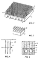
- Fig. 2 shows an unhooked part of the divertor-collector 4, which comprises a heat dissipation plate 7 crossed by channels 8 connected to the cooling circuit 5.
- the surface 9 of this plate facing the reaction chamber is covered with a ion protection layer 10, which consists of a brush of fibers such as 11 made of tungsten or another refractory material.
- these fibers are regularly distributed in lines on the surface 9, the fibers of one line being staggered relative to the fibers of the next line.
- the density of the fibers is actually greater than that shown in FIG. 2. It is indeed necessary to choose such a density that the probability of incidence of ions on the plate 7 is sufficiently low.
- a certain inclination of the surface 9 is chosen, so that the heat flux due to the impact of the ions is as low as possible. It may also be useful to implant the fibers 11 ′ in the heat dissipation plate 7 ′ not perpendicularly, as shown in FIG. 2, hand obliquely as shown in FIG. 3.
- the invention as described above has multiple advantages over a tile attached to or welded to a heat dissipation plate. It is obvious that even if a part of the surface of each fiber is not exposed to the ion beam, the fraction of the surface of the fibers actually exposed to ions is much larger than that of a massive surface. As a result, the local power density is significantly reduced, without the dimensions of the divertor-collector being increased.
- Another advantage lies in the difference in tensile stresses and moduli of elasticity between a fibrous material and the same material in massive form, because it is well known in the technology of composite materials than a solid in the form of weak fiber. diameter has much higher mechanical properties than in massive form.
- the presence of a dispersion of fibers is likely to stiffen the copper by a mechanism of curing by fibers which is very little sensitive to the temperature and to its variation.
- the physical properties, in particular the thermal conductivity are little affected by the presence of the fibers in the copper matrix.
- a method of manufacturing an entertainment manifold according to the invention may include a first step, during which the fibers are covered, at least over the part of their length which must be implanted in the copper plate, with a layer of copper. ; a second step then consists in compressing the bundle of fibers isostatically and at a temperature allowing the melting or sintering of the copper and the constitution of the plate.
- Another method of manufacturing an entertainment manifold can be constituted by an infiltration of liquid copper into a bundle of tungsten fibers.
- the divertor-collector in the case where the erosion rate is high, can be covered with a layer of liquid metal such as lithium, which is capable of withstanding very high thermal loads .
- a layer of liquid metal such as lithium
- the presence of the fibers in this case reduces the hydrodynamic instabilities of the liquid layer thanks to capillary forces retaining the liquid.
- This possibility is outlined in fig. 4, where we see the copper plate 7, the surface 9 of this plate and the fibers 11 projecting from this surface.
- a layer of lithium 12 is retained by capillary forces between the fibers.
- the recrystallization temperature of tungsten can be raised by an alloy of tungsten with rhenium, aluminum, silicon or thorium. This in return makes it possible to lengthen the free length of the fiber and thus to improve the ionic protection of the dissipation plate.
- the fibers have a diameter of around 10 ⁇ m and a total length of 3 mm, of which 1 mm is the free length outside the dissipation plate 7.
- the density of the fibers per cm2 is chosen between 100 and 10,000, preferably 4,000.
- FIG. 5 Yet another variant is shown in FIG. 5. It is a collector-entertainer which is not distinguished from that according to fig. 4 only by the fact that the space between the fibers is filled with a graphite matrix 13 instead of liquid lithium.
- the ion protection layer therefore consists of a graphite-carbon fiber composite.
- the mechanical and thermal coupling between the dissipation plate 7 and said layer is provided by the fibers 11, which are buried on the one hand in the copper of the plate 7 and on the other hand in the graphite matrix 13.
- a bundle of fibers is first dispersed in a thermosetting resin for a length corresponding to that of the protective layer. After polymerization of the resin, carbonization is carried out and then graphitation of the resin. Then, the fibers described above are applied to the process described above for implantation in copper. The end result is a double copper-fiber and graphite-fiber composite. If the fraction of the surface 9 covered by the fibers can reach 60%, there is a high thermal transfer by conduction, to which must be added the heat transmission by radiation between copper and graphite and that by conduction through the contact between copper and graphite.
- the invention is not limited to the exemplary embodiments described above. Without departing from the scope of the invention, it is possible to replace copper with another material which is a good conductor of heat such as zirconium or vanadium alloys or other refractory materials.
Landscapes
- Engineering & Computer Science (AREA)
- General Engineering & Computer Science (AREA)
- Physics & Mathematics (AREA)
- Plasma & Fusion (AREA)
- High Energy & Nuclear Physics (AREA)
- Mechanical Engineering (AREA)
- Manufacture Of Alloys Or Alloy Compounds (AREA)
- Physical Or Chemical Processes And Apparatus (AREA)
- Compositions Of Oxide Ceramics (AREA)
- Structure Of Emergency Protection For Nuclear Reactors (AREA)
- Powder Metallurgy (AREA)
Claims (10)
Applications Claiming Priority (2)
| Application Number | Priority Date | Filing Date | Title |
|---|---|---|---|
| LU86778A LU86778A1 (fr) | 1987-02-16 | 1987-02-16 | Diverteur-collecteur d'un reacteur nucleaire a fusion du type tokamak |
| LU86778 | 1987-02-16 |
Publications (2)
| Publication Number | Publication Date |
|---|---|
| EP0280940A1 EP0280940A1 (de) | 1988-09-07 |
| EP0280940B1 true EP0280940B1 (de) | 1991-03-27 |
Family
ID=19730872
Family Applications (1)
| Application Number | Title | Priority Date | Filing Date |
|---|---|---|---|
| EP88102002A Expired - Lifetime EP0280940B1 (de) | 1987-02-16 | 1988-02-11 | Divertor-Kollektor eines Tokamak-Nuklearfusionsreaktors |
Country Status (7)
| Country | Link |
|---|---|
| EP (1) | EP0280940B1 (de) |
| DE (1) | DE3862126D1 (de) |
| DK (1) | DK73388A (de) |
| ES (1) | ES2021766B3 (de) |
| GR (1) | GR3002170T3 (de) |
| LU (1) | LU86778A1 (de) |
| PT (1) | PT86769B (de) |
Families Citing this family (4)
| Publication number | Priority date | Publication date | Assignee | Title |
|---|---|---|---|---|
| FR2669382B1 (fr) * | 1990-11-16 | 1993-07-23 | Europ Propulsion | Dispositif de liaison entre deux corps susceptibles de se dilater de facon differente et procede de realisation d'un tel dispositif. |
| EP1063871A1 (de) * | 1999-06-24 | 2000-12-27 | European Community | Filterelement für das Divertor eines Tokamak-Kernfusionsreaktors, Divertor das dieses Filterelement gebraucht und Tokamak-Kernfusionsreaktor mit diesem Divertor |
| DE102004023368B4 (de) * | 2004-05-12 | 2006-08-03 | Forschungszentrum Karlsruhe Gmbh | Vorrichtung zum Temperieren einer Oberfläche |
| CN116994778B (zh) * | 2023-08-23 | 2026-04-17 | 四川大学 | 一种新型液固偏滤器 |
-
1987
- 1987-02-16 LU LU86778A patent/LU86778A1/fr unknown
-
1988
- 1988-02-11 DE DE8888102002T patent/DE3862126D1/de not_active Expired - Lifetime
- 1988-02-11 EP EP88102002A patent/EP0280940B1/de not_active Expired - Lifetime
- 1988-02-11 ES ES88102002T patent/ES2021766B3/es not_active Expired - Lifetime
- 1988-02-12 DK DK073388A patent/DK73388A/da not_active Application Discontinuation
- 1988-02-15 PT PT86769A patent/PT86769B/pt not_active IP Right Cessation
-
1991
- 1991-06-20 GR GR91400852T patent/GR3002170T3/el unknown
Also Published As
| Publication number | Publication date |
|---|---|
| EP0280940A1 (de) | 1988-09-07 |
| LU86778A1 (fr) | 1988-03-02 |
| PT86769B (pt) | 1993-08-31 |
| ES2021766B3 (es) | 1991-11-16 |
| DK73388D0 (da) | 1988-02-12 |
| DK73388A (da) | 1988-08-17 |
| PT86769A (pt) | 1989-02-28 |
| GR3002170T3 (en) | 1992-12-30 |
| DE3862126D1 (de) | 1991-05-02 |
Similar Documents
| Publication | Publication Date | Title |
|---|---|---|
| EP3154082B1 (de) | Verbesserte dbc-struktur, die mit einem trägerelement ausgestattet ist, in das ein material mit phasenumwandlung eingebaut ist | |
| EP0169117B1 (de) | Drehanoden-Röntgenröhre und Verfahren zur Befestigung einer Drehanode auf einer Trägerachse | |
| US5150748A (en) | Advanced survivable radiator | |
| WO2004092607A1 (fr) | Plaquettes de frein a disque ventilees | |
| US5943389A (en) | X-ray tube rotating anode | |
| FR3024923A1 (fr) | Traversee electrique et utilisation de celle-ci | |
| EP0280940B1 (de) | Divertor-Kollektor eines Tokamak-Nuklearfusionsreaktors | |
| FR2625605A1 (fr) | Anode tournante pour tube a rayons x | |
| WO1983003895A1 (fr) | Plaque de blindage, notamment pour blindage allege | |
| EP1636818B1 (de) | Röntgengeneratorröhre mit einem ausrichtbaren zielträgersystem | |
| EP1005083A1 (de) | Elektronisches Leistungselement mit Kühlvorrichtung | |
| CN113549867B (zh) | 一种大冷量传输全碳柔性冷链结构的制备方法 | |
| EP1459347B1 (de) | Vakuumröhre und verfahren zu deren fabrikation | |
| EP0660400B1 (de) | In der Elektronik als Träger gedruckter Schaltungen oder Bauelemente verwendbares Wärmeleitungselement und Herstellungsverfahren dafür | |
| EP0143011A1 (de) | Intensive Quelle von weichen Röntgenstrahlen mit durch Explosion einer Folie erhaltenen zylindrisch-kompressierten Plasma | |
| RU2403632C2 (ru) | Первый стеновой компонент с отрезком трубы | |
| EP0020262B1 (de) | Isolierte Kollektoreinheit für Leistungsröhren und Röhre mit einem solchen Kollektor | |
| FR2699003A1 (fr) | Collecteur refroidi par conduction à forte dépression et grande capacité thermique. | |
| EP0858107A1 (de) | Wärmeaustauscher für elektronischen Bauteile und elektrotechnischen Geräte | |
| EP1969149B1 (de) | Thermische isolierende schirm zum schützen eines elektromagnetischen induktors und ausrüstung von thermischen behandlung versehen mit solchem schirm | |
| FR2686732A1 (fr) | Anode en graphite pour tube a rayons x et tube ainsi obtenu. | |
| FR2810395A1 (fr) | Dissipateur thermique a performances thermiques accrues et procede de fabrication | |
| FR2459552A1 (fr) | Support pour composants electriques | |
| EP0430767A1 (de) | Röntgenröhrenanode mit hohen mechanischen Festigkeitswerten | |
| EP0540384A1 (de) | Kühlvorrichtung für eine Mikrowellenröhre |
Legal Events
| Date | Code | Title | Description |
|---|---|---|---|
| PUAI | Public reference made under article 153(3) epc to a published international application that has entered the european phase |
Free format text: ORIGINAL CODE: 0009012 |
|
| AK | Designated contracting states |
Kind code of ref document: A1 Designated state(s): BE DE ES FR GB GR IT LU NL |
|
| 17P | Request for examination filed |
Effective date: 19881026 |
|
| 17Q | First examination report despatched |
Effective date: 19900504 |
|
| GRAA | (expected) grant |
Free format text: ORIGINAL CODE: 0009210 |
|
| AK | Designated contracting states |
Kind code of ref document: B1 Designated state(s): BE DE ES FR GB GR IT LU NL |
|
| REF | Corresponds to: |
Ref document number: 3862126 Country of ref document: DE Date of ref document: 19910502 |
|
| ITF | It: translation for a ep patent filed | ||
| GBT | Gb: translation of ep patent filed (gb section 77(6)(a)/1977) | ||
| PGFP | Annual fee paid to national office [announced via postgrant information from national office to epo] |
Ref country code: BE Payment date: 19911216 Year of fee payment: 5 |
|
| PGFP | Annual fee paid to national office [announced via postgrant information from national office to epo] |
Ref country code: LU Payment date: 19911217 Year of fee payment: 5 |
|
| PGFP | Annual fee paid to national office [announced via postgrant information from national office to epo] |
Ref country code: GB Payment date: 19920102 Year of fee payment: 5 |
|
| PLBE | No opposition filed within time limit |
Free format text: ORIGINAL CODE: 0009261 |
|
| STAA | Information on the status of an ep patent application or granted ep patent |
Free format text: STATUS: NO OPPOSITION FILED WITHIN TIME LIMIT |
|
| PGFP | Annual fee paid to national office [announced via postgrant information from national office to epo] |
Ref country code: GR Payment date: 19920211 Year of fee payment: 5 |
|
| PGFP | Annual fee paid to national office [announced via postgrant information from national office to epo] |
Ref country code: ES Payment date: 19920214 Year of fee payment: 5 |
|
| PGFP | Annual fee paid to national office [announced via postgrant information from national office to epo] |
Ref country code: FR Payment date: 19920226 Year of fee payment: 5 |
|
| PGFP | Annual fee paid to national office [announced via postgrant information from national office to epo] |
Ref country code: NL Payment date: 19920229 Year of fee payment: 5 |
|
| 26N | No opposition filed | ||
| EPTA | Lu: last paid annual fee | ||
| PGFP | Annual fee paid to national office [announced via postgrant information from national office to epo] |
Ref country code: DE Payment date: 19920619 Year of fee payment: 5 |
|
| REG | Reference to a national code |
Ref country code: GR Ref legal event code: FG4A Free format text: 3002170 |
|
| PG25 | Lapsed in a contracting state [announced via postgrant information from national office to epo] |
Ref country code: LU Free format text: LAPSE BECAUSE OF NON-PAYMENT OF DUE FEES Effective date: 19930211 Ref country code: GB Effective date: 19930211 |
|
| PG25 | Lapsed in a contracting state [announced via postgrant information from national office to epo] |
Ref country code: ES Free format text: LAPSE BECAUSE OF NON-PAYMENT OF DUE FEES Effective date: 19930212 |
|
| PG25 | Lapsed in a contracting state [announced via postgrant information from national office to epo] |
Ref country code: BE Effective date: 19930228 |
|
| BERE | Be: lapsed |
Owner name: COMMUNAUTE EUROPEENNE DE L'ENERGIE ATOMIQUE EURAT Effective date: 19930228 |
|
| PG25 | Lapsed in a contracting state [announced via postgrant information from national office to epo] |
Ref country code: GR Free format text: THE PATENT HAS BEEN ANNULLED BY A DECISION OF A NATIONAL AUTHORITY Effective date: 19930831 |
|
| PG25 | Lapsed in a contracting state [announced via postgrant information from national office to epo] |
Ref country code: NL Effective date: 19930901 |
|
| GBPC | Gb: european patent ceased through non-payment of renewal fee |
Effective date: 19930211 |
|
| NLV4 | Nl: lapsed or anulled due to non-payment of the annual fee | ||
| PG25 | Lapsed in a contracting state [announced via postgrant information from national office to epo] |
Ref country code: FR Effective date: 19931029 |
|
| PG25 | Lapsed in a contracting state [announced via postgrant information from national office to epo] |
Ref country code: DE Effective date: 19931103 |
|
| REG | Reference to a national code |
Ref country code: FR Ref legal event code: ST |
|
| REG | Reference to a national code |
Ref country code: GR Ref legal event code: MM2A Free format text: 3002170 |
|
| REG | Reference to a national code |
Ref country code: ES Ref legal event code: FD2A Effective date: 19990301 |
|
| PG25 | Lapsed in a contracting state [announced via postgrant information from national office to epo] |
Ref country code: IT Free format text: LAPSE BECAUSE OF NON-PAYMENT OF DUE FEES;WARNING: LAPSES OF ITALIAN PATENTS WITH EFFECTIVE DATE BEFORE 2007 MAY HAVE OCCURRED AT ANY TIME BEFORE 2007. THE CORRECT EFFECTIVE DATE MAY BE DIFFERENT FROM THE ONE RECORDED. Effective date: 20050211 |