EP1969660B1 - Brennstoffzelle und brennstoffzellenstapel - Google Patents
Brennstoffzelle und brennstoffzellenstapel Download PDFInfo
- Publication number
- EP1969660B1 EP1969660B1 EP06834848A EP06834848A EP1969660B1 EP 1969660 B1 EP1969660 B1 EP 1969660B1 EP 06834848 A EP06834848 A EP 06834848A EP 06834848 A EP06834848 A EP 06834848A EP 1969660 B1 EP1969660 B1 EP 1969660B1
- Authority
- EP
- European Patent Office
- Prior art keywords
- channel
- separator
- fuel gas
- fuel cell
- oxygen
- Prior art date
- Legal status (The legal status is an assumption and is not a legal conclusion. Google has not performed a legal analysis and makes no representation as to the accuracy of the status listed.)
- Not-in-force
Links
Images


Classifications
-
- H—ELECTRICITY
- H01—ELECTRIC ELEMENTS
- H01M—PROCESSES OR MEANS, e.g. BATTERIES, FOR THE DIRECT CONVERSION OF CHEMICAL ENERGY INTO ELECTRICAL ENERGY
- H01M8/00—Fuel cells; Manufacture thereof
- H01M8/04—Auxiliary arrangements, e.g. for control of pressure or for circulation of fluids
- H01M8/04082—Arrangements for control of reactant parameters, e.g. pressure or concentration
- H01M8/04089—Arrangements for control of reactant parameters, e.g. pressure or concentration of gaseous reactants
-
- H—ELECTRICITY
- H01—ELECTRIC ELEMENTS
- H01M—PROCESSES OR MEANS, e.g. BATTERIES, FOR THE DIRECT CONVERSION OF CHEMICAL ENERGY INTO ELECTRICAL ENERGY
- H01M8/00—Fuel cells; Manufacture thereof
- H01M8/02—Details
-
- H—ELECTRICITY
- H01—ELECTRIC ELEMENTS
- H01M—PROCESSES OR MEANS, e.g. BATTERIES, FOR THE DIRECT CONVERSION OF CHEMICAL ENERGY INTO ELECTRICAL ENERGY
- H01M8/00—Fuel cells; Manufacture thereof
- H01M8/02—Details
- H01M8/0202—Collectors; Separators, e.g. bipolar separators; Interconnectors
- H01M8/0247—Collectors; Separators, e.g. bipolar separators; Interconnectors characterised by the form
-
- H—ELECTRICITY
- H01—ELECTRIC ELEMENTS
- H01M—PROCESSES OR MEANS, e.g. BATTERIES, FOR THE DIRECT CONVERSION OF CHEMICAL ENERGY INTO ELECTRICAL ENERGY
- H01M8/00—Fuel cells; Manufacture thereof
- H01M8/02—Details
- H01M8/0202—Collectors; Separators, e.g. bipolar separators; Interconnectors
- H01M8/0258—Collectors; Separators, e.g. bipolar separators; Interconnectors characterised by the configuration of channels, e.g. by the flow field of the reactant or coolant
-
- H—ELECTRICITY
- H01—ELECTRIC ELEMENTS
- H01M—PROCESSES OR MEANS, e.g. BATTERIES, FOR THE DIRECT CONVERSION OF CHEMICAL ENERGY INTO ELECTRICAL ENERGY
- H01M8/00—Fuel cells; Manufacture thereof
- H01M8/04—Auxiliary arrangements, e.g. for control of pressure or for circulation of fluids
- H01M8/04007—Auxiliary arrangements, e.g. for control of pressure or for circulation of fluids related to heat exchange
- H01M8/04014—Heat exchange using gaseous fluids; Heat exchange by combustion of reactants
-
- H—ELECTRICITY
- H01—ELECTRIC ELEMENTS
- H01M—PROCESSES OR MEANS, e.g. BATTERIES, FOR THE DIRECT CONVERSION OF CHEMICAL ENERGY INTO ELECTRICAL ENERGY
- H01M8/00—Fuel cells; Manufacture thereof
- H01M8/24—Grouping of fuel cells, e.g. stacking of fuel cells
-
- H—ELECTRICITY
- H01—ELECTRIC ELEMENTS
- H01M—PROCESSES OR MEANS, e.g. BATTERIES, FOR THE DIRECT CONVERSION OF CHEMICAL ENERGY INTO ELECTRICAL ENERGY
- H01M8/00—Fuel cells; Manufacture thereof
- H01M8/24—Grouping of fuel cells, e.g. stacking of fuel cells
- H01M8/241—Grouping of fuel cells, e.g. stacking of fuel cells with solid or matrix-supported electrolytes
- H01M8/2425—High-temperature cells with solid electrolytes
- H01M8/2432—Grouping of unit cells of planar configuration
-
- H—ELECTRICITY
- H01—ELECTRIC ELEMENTS
- H01M—PROCESSES OR MEANS, e.g. BATTERIES, FOR THE DIRECT CONVERSION OF CHEMICAL ENERGY INTO ELECTRICAL ENERGY
- H01M8/00—Fuel cells; Manufacture thereof
- H01M8/24—Grouping of fuel cells, e.g. stacking of fuel cells
- H01M8/2457—Grouping of fuel cells, e.g. stacking of fuel cells with both reactants being gaseous or vaporised
-
- H—ELECTRICITY
- H01—ELECTRIC ELEMENTS
- H01M—PROCESSES OR MEANS, e.g. BATTERIES, FOR THE DIRECT CONVERSION OF CHEMICAL ENERGY INTO ELECTRICAL ENERGY
- H01M8/00—Fuel cells; Manufacture thereof
- H01M8/24—Grouping of fuel cells, e.g. stacking of fuel cells
- H01M8/2465—Details of groupings of fuel cells
- H01M8/2483—Details of groupings of fuel cells characterised by internal manifolds
-
- H—ELECTRICITY
- H01—ELECTRIC ELEMENTS
- H01M—PROCESSES OR MEANS, e.g. BATTERIES, FOR THE DIRECT CONVERSION OF CHEMICAL ENERGY INTO ELECTRICAL ENERGY
- H01M8/00—Fuel cells; Manufacture thereof
- H01M8/24—Grouping of fuel cells, e.g. stacking of fuel cells
- H01M8/2465—Details of groupings of fuel cells
- H01M8/2484—Details of groupings of fuel cells characterised by external manifolds
-
- H—ELECTRICITY
- H01—ELECTRIC ELEMENTS
- H01M—PROCESSES OR MEANS, e.g. BATTERIES, FOR THE DIRECT CONVERSION OF CHEMICAL ENERGY INTO ELECTRICAL ENERGY
- H01M8/00—Fuel cells; Manufacture thereof
- H01M8/06—Combination of fuel cells with means for production of reactants or for treatment of residues
- H01M8/0606—Combination of fuel cells with means for production of reactants or for treatment of residues with means for production of gaseous reactants
- H01M8/0612—Combination of fuel cells with means for production of reactants or for treatment of residues with means for production of gaseous reactants from carbon-containing material
-
- Y—GENERAL TAGGING OF NEW TECHNOLOGICAL DEVELOPMENTS; GENERAL TAGGING OF CROSS-SECTIONAL TECHNOLOGIES SPANNING OVER SEVERAL SECTIONS OF THE IPC; TECHNICAL SUBJECTS COVERED BY FORMER USPC CROSS-REFERENCE ART COLLECTIONS [XRACs] AND DIGESTS
- Y02—TECHNOLOGIES OR APPLICATIONS FOR MITIGATION OR ADAPTATION AGAINST CLIMATE CHANGE
- Y02E—REDUCTION OF GREENHOUSE GAS [GHG] EMISSIONS, RELATED TO ENERGY GENERATION, TRANSMISSION OR DISTRIBUTION
- Y02E60/00—Enabling technologies; Technologies with a potential or indirect contribution to GHG emissions mitigation
- Y02E60/30—Hydrogen technology
- Y02E60/50—Fuel cells
Definitions
- the present invention relates to a fuel cell formed by stacking an electrolyte electrode assembly and a separator.
- the electrolyte electrode assembly includes an anode, a cathode, and an electrolyte interposed between the anode and the cathode. Further; the present invention relates to a fuel cell stack formed by stacking a plurality of fuel cells.
- a solid oxide fuel cell (SOFC) having a seal free (sealless) structure employs an electrolyte made up of an ion-conductive solid oxide such as stabilized zirconia.
- the electrolyte is interposed between an anode and a cathode to form an electrolyte electrode assembly.
- the electrolyte electrode assembly is interposed between separators (bipolar plates).
- separators bipolar plates.
- the operating temperature of the fuel cell is high, about 800°C. Therefore, when the reacted fuel gas containing unconsumed reactant gases therein (hereinafter also referred to as the off gas) is discharged to an area around the fuel cell stack, and is mixed with an oxygen-containing gas to induce combustion, the temperature of the fuel cell stack becomes high locally. Under these circumstances, durability of the fuel cell is lowered, and operation of the fuel cell stack cannot be performed stably. Further, since the temperature of the exhaust gas after combustion becomes higher than the operating temperature, the temperature difference between the oxygen-containing gas supplied to the fuel cell stack prior to the power generation reaction and the exhaust gas becomes excessively large. Therefore, a significant non-uniform temperature distribution occurs within the fuel cell stack, and power generation performance is degraded undesirably.
- a solid oxide fuel cell as disclosed in Japanese Laid Open Patent Publication No. 2005-85520 , is known.
- the fuel cell is formed by stacking a power generation cell 1, a fuel electrode current collector 2, an air electrode current collector 3, and separators 4a, 4b.
- the power generation cell 1 includes a fuel electrode layer 1b, an air electrode layer 1c, and a solid electrolyte layer 1a interposed between the fuel electrode layer 1b and the air electrode layer 1c.
- the fuel electrode current collector 2 is provided outside the fuel electrode layer 1b
- the air electrode current collector 3 is provided outside the air electrode layer 1c.
- the separator 4a includes a fuel gas channel 5 for supplying a fuel gas substantially from a center portion of the surface of the separator 4a, which faces the fuel electrode collector 2.
- the separator 4b has an oxygen-containing gas channel 6 for supplying an oxygen-containing gas from the separator 4b, which faces the air electrode current collector 3.
- a ring shaped metal cover covers the outer circumferential portion of a circular porous metal body, wherein a large number of gas discharge holes 7 are provided over the entire side portion of the cover.
- gas is discharged from the outer circumferential portion of the fuel electrode current collector 2 only through the gas discharge holes 7.
- the fuel gas diffuses into the porous metal body and is not emitted from the entire outer circumferential portion of the fuel electrode current collector 2.
- an amount of the fuel gas, which is not used during power generation, and which is discharged from the outer circumferential portion is suppressed, and thus it is possibly to prevent back diffusion of air toward the fuel electrode.
- the separator 4a is stacked on the fuel electrode collector 2, whereby the exhaust gas discharged from the gas discharge holes 7 is combusted near the separator 4a, and thus the temperature of the exhaust gas becomes significantly high.
- the temperature difference between the region near the inlet where the oxygen-containing gas is supplied and the region near the outlet where the exhaust gas is discharged becomes large. Therefore, a significant non-uniform temperature distribution occurs in the separator 4a, and power generation performance is degraded undesirably.
- an object of the present invention is to provide a fuel cell and a fuel cell stack having a simple structure, in which it is possible to reliably prevent an excessive increase in the temperature of the exhaust gas, to prevent a non-uniform temperature distribution in the fuel cell stack, and to effectively prevent damage to the electrolyte electrode assembly and the separator; thereby improving power generation performance.
- the present invention relates to a solid oxide fuel cell formed by stacking an electrolyte electrode assembly and a separator.
- the electrolyte electrode assembly includes an anode, a cathode, and an electrolyte interposed between the anode and the cathode.
- a fuel gas channel for supplying a fuel gas along a surface of the anode is formed on one surface of the separator, and an oxygen-containing gas channel for supplying an oxygen-containing gas along a surface of another cathode is formed on the other surface of the separator.
- a fuel gas supply channel is provided on the other surface of the separator.
- the fuel gas supply channel is connected to a fuel gas supply unit, serving as a passage for the fuel gas before consumption and extending in a stacking direction, and to a fuel gas inlet for supplying the fuel gas into the fuel gas channel.
- An oxygen-containing gas supply unit serving as a passage for the oxygen-containing gas before consumption, extends in the stacking direction, in order to supply the oxygen-containing gas to the oxygen-containing gas channel.
- a channel member contacts the other surface of the separator and covers the fuel gas supply channel and a discharge groove provided on the other surface of the separator.
- the fuel gas discharge channel is formed by a through hole, which extends through the separator, and the discharge groove.
- the discharge groove is connected to the through hole, extending outwardly from the electrolyte electrode assembly, and opens toward the oxygen-containing gas supply unit.
- the fuel gas channel has an end point at a position corresponding to an outer circumferential portion of the electrolyte electrode-assembly, wherein the end point of the fuel gas channel is connected to a fuel gas discharge channel, which emits the fuel gas consumed in the electrolyte electrode assembly to the oxygen-containing gas supply unit, from a position spaced outwardly from an outer circumference of the electrolyte electrode assembly.
- the fuel gas channel includes a channel unit provided on one surface of the separator, wherein the channel unit is connected from the fuel gas inlet to the fuel gas discharge channel.
- a ring shaped protrusion is provided on one surface of the separator in tight contact with an outer circumferential portion of the anode.
- the channel unit is formed by a groove, a plurality of protrusions, or a deformable elastic channel member, which is disposed in tight contact with the anode.
- the oxygen-containing gas channel is formed by a deformable elastic channel member provided on the other surface of the separator, and which is disposed in tight contact with the cathode.
- the cathode is disposed suitably in tight contact with the separator, and hence an improvement in the performance of collecting electricity from the fuel cell can be achieved.
- an area in which the elastic channel member is disposed is smaller than a power generation area of the anode.
- the elastic channel member is an electrically conductive mesh member or a felt member.
- the structure is simplified and low in cost.
- the oxygen-containing gas channel is formed by a plurality of protrusions provided on the other surface of the separator.
- the load in the stacking direction is efficiently transmitted through the protrusions, whereby an improvement in the performance of collecting electricity from the fuel cell is achieved.
- the protrusions are defined by a plurality of solid portions formed by etching on one surface of the separator.
- the shapes and positions of the protrusions can be changed arbitrarily and easily, whereby an improvement in the performance of collecting electricity from the fuel cell can be achieved.
- a fuel cell stack formed by stacking a plurality of solid oxide fuel cells as defined above further comprises an exhaust gas channel for discharging a reactant gas, after consumption in the reaction in the electrolyte electrode assembly, as an exhaust gas in the stacking direction of the electrolyte electrode assembly and the separator.
- the fuel gas supply unit is provided hermetically with respect to the oxygen-containing gas supply unit, wherein the fuel gas supply channel connects the fuel gas channel and the fuel gas supply unit, and is disposed along the separator surface so as to intersect with the oxygen-containing gas supply unit that extends in the stacking direction.
- the fuel gas prior to consumption is heated beforehand by the heat of the exhaust gas.
- an improvement in heat efficiency is achieved.
- the exhaust gas channel is provided around the separator.
- heat insulation is provided around the fuel cell, whereby an improvement in heat efficiency is achieved.
- the fuel gas supply unit is provided hermetically at a center portion of the separator, and the oxygen-containing gas supply unit is provided at an inner region of the separator.
- the oxygen-containing gas flows outwardly from the inner region of the separator. Therefore, the exhaust gas is suitably discharged to the outside of the separator.
- the fuel gas inlet is provided at the center of the electrolyte electrode assembly.
- the fuel cell has a compact structure, whereby the influence of heat distortion thereon can be avoided.
- the present invention relates to a fuel cell stack formed by stacking a plurality of fuel cells as described above.
- the exhaust gas contains unconsumed gases therein.
- the exhaust gas containing such unconsumed gases is referred to as an off gas.
- the off gas is emitted from a position spaced outwardly from the outer circumference of the electrolyte electrode assembly.
- the off gas is emitted to the oxygen-containing gas supply unit, combustion occurs by reaction of the off gas and the oxygen-containing gas within the oxygen-containing gas supply unit, whereby the off gas becomes diluted.
- the oxygen-containing gas supplied to the oxygen-containing gas supply unit is heated immediately before it is supplied to the electrolyte electrode assembly. Therefore, an improvement in heat efficiency is achieved advantageously. Accordingly, it is possible to prevent an excessive increase in the temperature of the exhaust gas, and to prevent the separator from being heated locally, thus maintaining a uniform temperature distribution within the separator or the fuel cell stack.
- FIG. 1 is a partial cross sectional view showing a fuel cell system 10 including fuel cells 11 according to a first embodiment of the present invention.
- FIG. 2 is a perspective view schematically showing a fuel cell stack 12 formed by stacking a plurality of the fuel cells 11 in a direction indicated by the arrow A.
- the fuel cell system 10 is used in various applications, including stationary and mobile applications.
- the fuel cell system 10 may be mounted on a vehicle.
- the fuel cell system 10 includes the fuel cell stack 12, a heat exchanger 14, a reformer 16, and a casing 18.
- the heat exchanger 14 heats an oxygen-containing gas before it is supplied to the fuel cell stack 12.
- the reformer 16 reforms fuel in order to produce a fuel gas.
- the fuel cell stack 12, the heat exchanger 14, and the reformer 16 are disposed within the casing 18.
- a fluid unit 19 including at least the heat exchanger 14 and the reformer 16 is disposed on one side of the fuel cell stack 12, and a load applying mechanism 21, which applies a tightening load to the fuel cells 11 in the stacking direction indicated by the arrow A, is disposed on the other side of the fuel cell stack 12.
- the fluid unit 19 and the load applying mechanism 21 are provided symmetrically with respect to a central axis of the fuel cell stack 12.
- the fuel cell 11 is a solid oxide fuel cell (SOFC). As shown in FIGS. 3 and 4 , the fuel cell 11 includes electrolyte electrode assemblies 26. Each of the electrolyte electrode assemblies 26 includes a cathode 22, an anode 24, and an electrolyte (electrolyte plate) 20 interposed between the cathode 22 and the anode 24.
- the electrolyte 20 is made of an ion-conductive solid oxide, such as stabilized zirconia.
- the electrolyte electrode assembly 26 has a circular disk shape.
- a barrier layer (not shown) is provided at least on the outer circumferential edge of the electrolyte electrode assembly 26 in order to prevent the entry and emission of the oxygen-containing gas and the fuel gas.
- a plurality of, e.g., eight, electrolyte electrode assemblies 26 are sandwiched between a pair of separators 28 to form the fuel cell 11.
- the eight electrolyte electrode assemblies 26 are concentric with respect to a fuel gas supply passage 30 that extends through the center of the separators 28.
- each of the separators 28 comprises a single metal plate of, e.g., a stainless alloy or a carbon plate.
- the separator 28 has a first small diameter end portion (reactant gas supply unit) 32.
- the fuel gas supply passage 30 extends through the center of the first small diameter end portion 32.
- the first small diameter end portion 32 is formed integrally together with circular disks 36 through a plurality of first bridges 34.
- the first bridges 34 extend radially outwardly from the first small diameter end portion 32 at equal angles (intervals).
- the circular disk 36 and the electrolyte electrode assembly 26 are of substantially the same size.
- a fuel gas inlet 38 for supplying the fuel gas is formed at the center of the circular disk 36, or at an upstream position that is deviated from the center of the circular disk 36 in the flow direction of the oxygen-containing gas.
- Each of the circular disks 36 includes a fuel gas channel 46 on its surface 36a, which contacts the anode 24 in order to supply a fuel gas along a surface of the anode 24.
- the fuel gas channel 46 includes a plurality of ring shaped grooves (channel units) 48a to 48f formed concentrically around the fuel gas inlet 38 on the circular disk 36.
- the ring shaped groove 48a having the smallest diameter is connected to the fuel gas inlet 38 through a straight groove 50.
- the diameters of the ring shaped grooves become larger toward the outside, from the ring shaped groove 48a to the ring shaped groove 48f.
- the ring shaped grooves 48a to 48f are connected together through connection grooves 52, which are arranged on the front side and back side alternately, in the direction indicated by the arrow B.
- the ring shaped groove 48f having the largest diameter is connected to discharge holes (through holes) 54a, 54b at its rear end (inner portion of the separator 28) in the direction indicated by the arrow B.
- the fuel gas inlet 38 is connected to the fuel gas discharge channel 61, as described later, by the ring shaped grooves 48a to 48f through the discharge holes 54a, 54b.
- a ring shaped protrusion 56 is provided in the outer circumferential region of each circular disk 36. The ring shaped protrusion 56 makes tight contact with the outer circumferential portion of the anode 24 of the electrolyte electrode assembly 26.
- each of the circular disks 36 has a substantially planar surface 36b, which contacts the cathode 22.
- a fuel gas supply channel 58 extends from the first small diameter end portion 32 to the first bridge 34.
- the fuel gas supply channel 58 connects the fuel gas supply passage 30 to the fuel gas inlet 38.
- the fuel gas supply channel 58 may be formed by etching.
- Plate shaped extensions 57a, 57b are formed integrally with the first bridge 34.
- the plate shaped extensions 57a, 57b extend from the inner ends of the respective circular disks 36 toward the center of the separator 28.
- Discharge grooves 59a, 59b are formed in the plate shaped extensions 57a, 57b. From the surface 36b of the circular disk 36, the discharge grooves 59a, 59b are connected to the discharge holes 54a, 54b.
- the discharge grooves 59a, 59b open toward an oxygen-containing gas supply unit 74, as described later, through the sides of the plate shaped extensions 57a, 57b (see FIG. 8 ).
- the discharge holes 54a, 54b and the discharge grooves 59a, 59b collectively form the fuel gas discharge channel 61.
- the distance H between the end of the fuel gas discharge channel 61 and the outer circumferential surface of the electrolyte electrode assembly 26 is predetermined, such that the separator 28 and the electrolyte electrode assembly 26 can suitably avoid being influenced by the combustion gas, formed by a mixture of the off gas and the oxygen-containing gas.
- a channel member 60 is fixed to the separator 28, e.g., by brazing or laser welding, on a surface facing the cathode 22.
- the channel member 60 has a planar shape, and includes a second small diameter end portion 62.
- the fuel gas supply passage 30 extends through the center of the second small diameter end portion 62.
- Eight second bridges 64 extend radially from the second small diameter end portion 62. Wide portions 66a, 66b are provided in the middle of each of the second bridges 64, at positions corresponding to the plate shaped extensions 57a, 57b of each circular disk 36.
- Each of the second bridges 64 is fixed to the separator 28, extending from the first bridge 34 to the surface 36b of the circular disk 36, and covering the fuel gas inlet 38 (see FIG. 7 ).
- the wide portions 66a, 66b are fixed to the plate shaped extensions 57a, 57b of each circular disk 36.
- a deformable elastic channel member such as an electrically conductive mesh member 72
- the electrically conductive mesh member 72 forms an oxygen-containing gas channel 70 for supplying an oxygen-containing gas along a surface of the cathode 22, and the electrically conductive mesh member 72 is maintained in tight contact with the cathode 22.
- a felt member for example.
- the mesh member 72 may be made of stainless steel wire rods (SUS material), and has a circular disk shape.
- the thickness of the mesh member 72 is determined such that the mesh member 72 can be deformed elastically when a load in the stacking direction (indicated by the arrow A) is applied to the mesh member 72.
- the mesh member 72 directly contacts the surface 36b of the circular disk 36, and has cutouts 72a, 72b, which serve as spaces for providing the channel member 60.
- the area in which the mesh member 72 is disposed is smaller than the power generation area of the anode 24.
- the oxygen-containing gas channel 70 which is formed in the mesh member 72, is connected to the oxygen-containing gas supply unit 74.
- the oxygen-containing gas is supplied in the direction indicated by the arrow B, through the space between the inner circumferential edge of the electrolyte electrode assembly 26 and the inner circumferential edge of the circular disk 36.
- the oxygen-containing gas supply unit 74 extends in the stacking direction indicated by the arrow A, among the respective circular disks 36 and the first bridges 34.
- Insulating seals 76 for sealing the fuel gas supply passage 30 are provided between the separators 28.
- the insulating seals 76 may be made of a mica material, or a ceramic material.
- An exhaust gas channel 78 for the fuel cells 11 is formed outside of the circular disks 36.
- the fuel cell stack 12 includes end plates 80a, 80b provided at opposite ends of the fuel cells 11 in the stacking direction.
- the end plate 80a has a substantially circular disk shape.
- a ring shaped portion 82 protrudes from the outer circumferential end of the end plate 80a, and a groove-84 is formed around the ring shaped portion 82.
- a columnar projection 86 is formed at the center of the ring shaped portion 82. The columnar projection 86 protrudes in the same direction as the ring shaped portion 82.
- a stepped hole 88 is formed within the projection 86.
- the end plate 80a has holes 90 and screw holes 92 formed within a same virtual circle around the projection 86.
- the holes 90 and the screw holes 92 are arranged alternately, while being spaced from each other at predetermined angles (intervals), at positions corresponding to the respective spaces of the oxygen-containing gas supply unit 74 formed between the first and second bridges 34, 64.
- the diameter of the end plate 80b is larger than the diameter of the end plate 80a.
- the end plate 80a is an electrically conductive thin plate.
- the casing 18 includes a first case unit 96a containing the load applying mechanism 21, and a second case unit 96b containing the fuel cell stack 12.
- the end plate 80b and an insulating member are sandwiched between the first case unit 96a and the second case unit 96b.
- the insulating member is provided on the side of the second case unit 96b.
- the joined portion between the first case unit 96a and the second case unit 96b is tightened by screws 98 and nuts 100.
- the end plate 80b functions as a gas barrier, which prevents hot exhaust gas or the hot air from the fluid unit 19 from entering into the load applying mechanism 21.
- the fluid unit 19 is disposed symmetrically with respect to the central axis of the fuel cell stack 12.
- the substantially cylindrical reformer 16 is provided coaxially inside of the substantially ring shaped heat exchanger 14.
- a wall plate 106 is fixed to the groove 84 around the end plate 80a, so as to form a channel member 108.
- the heat exchanger 14 and the reformer 16 are directly connected to the channel member 108.
- a chamber 108a is formed in the channel member 108, wherein the chamber 108a is temporarily filled with air heated by the heat exchanger 14.
- the holes 90 form openings for supplying the air, which temporarily fills the chamber 108a, to the fuel cell stack 12.
- a fuel gas supply pipe 110 and a reformed gas supply pipe 112 are connected to the reformer 16.
- the fuel gas supply pipe 110 extends to the outside from the head plate 104.
- the reformed gas supply pipe 112 is inserted into the stepped hole 88 of the end plate 80a, and is connected to the fuel gas supply passage 30.
- An air supply pipe 114 and an exhaust gas pipe 116 are connected to the head plate 104.
- the load applying mechanism 21 includes a first tightening unit 122a for applying a first tightening load T1 to a region around (or near) the fuel gas supply passage 30, and a second tightening unit 122b for applying a second tightening load T2 to the electrolyte electrode assemblies 26.
- the second tightening load T2 is smaller than the first tightening load T1 (T1 > T2).
- the first tightening unit 122a includes relatively short first tightening bolts 124a, which are screwed into the screw holes 92 formed along one diagonal line of the end plate 80a.
- the first tightening bolts 124a extend in the stacking direction of the fuel cells 11, and engage with a first presser plate 126a.
- the first tightening bolts 124a also are provided in the oxygen-containing gas supply unit 74 extending through the separators 28.
- the first presser plate 126a is formed by a narrow plate, and engages with a central position of the separator 28 so as to cover the fuel gas supply passage 30.
- the second tightening unit 122b includes relatively long second tightening bolts 124b, which are screwed into screw holes 92 formed along the other diagonal line of the end plate 80a. Ends of the second tightening bolts 124b extend through a second presser plate 126b having a curved outer section. Nuts 127 are fitted onto the ends of the second tightening bolts 124b. The second tightening bolts 124b also are provided in the oxygen-containing gas supply unit 74 extending through the separators 28.
- Springs 128 and spring seats 129 are provided in respective circular portions of the second presser plate 126b, at positions corresponding to the electrolyte electrode assemblies 26 on the circular disks 36 of the fuel cell 11.
- the springs 128 are ceramic springs, for example.
- the channel member 60 is joined to the surface of the separator 28 facing the cathode 22.
- a fuel gas supply channel 58 which is connected to the fuel gas supply passage 30, is formed between the separator 28 and the channel member 60.
- the fuel gas supply channel 58 is connected to the fuel gas channel 46 through the fuel gas inlet 38 (see FIG. 7 ).
- the fuel gas discharge channel 61 is formed by connecting the discharge holes 54a, 54b and the discharge grooves 59a, 59b together, between the separator 28 and the channel member 60 (see FIGS. 5 and 8 ).
- the ring shaped insulating seal 76 is provided on each of the separators 28 around the fuel gas supply passage 30.
- the separator 28 is fabricated in the following manner. Specifically, eight electrolyte electrode assemblies 26 are interposed between a pair of the separators 28 in order to form the fuel cell 11. As shown in FIGS. 3 and 4 , the electrolyte electrode assemblies 26 are interposed between the surface 36a of one separator 28 and the surface 36b of the other separator 28.
- the fuel gas inlet 38 is positioned substantially at a center location in each of the anodes 24.
- the mesh member 72 is provided between the surface 36b of the separator 28 and the electrolyte electrode assembly 26.
- the two cutouts 72a, 72b of the mesh member 72 are provided at positions corresponding to the channel member 60.
- a plurality of fuel cells 11 are stacked in the direction indicated by the arrow A, and the end plates 80a, 80b are provided at opposite ends in the stacking direction. As shown in FIGS. 1 and 2 , a desired tightening load in the direction indicated by the arrow A is applied to the fuel cells 11 through the load applying mechanism 21.
- the end plate 80b of the fuel cell stack 12 is sandwiched between the first case unit 96a and the second case unit 96b of the casing 18.
- the first case unit 96a and the second case unit 96b are fixed together by screws 98 and nuts 100.
- the fluid unit 19 is mounted inside the second case unit 96b.
- the wall plate 106 of the fluid unit 19 is attached to the groove 84 around the end plate 80a.
- the channel member 108 is provided between the end plate 80a and the wall plate 106.
- a fuel methane, ethane, propane, or the like
- an oxygen-containing gas hereinafter referred to simply as "air"
- the fuel is reformed as it passes through the reformer 16, thereby producing a fuel gas (hydrogen-containing gas).
- the fuel gas is supplied to the fuel gas supply passage 30 of the fuel cell stack 12.
- the fuel gas moves in the stacking direction, as indicated by the arrow A, and flows into the fuel gas supply channel 58 through the separator 28 of each fuel cell 11 (see FIG. 7 ).
- the fuel gas flows along the fuel gas supply channel 58 between the first and second bridges 34, 64, and flows into the fuel gas inlets 38 of the circular disks 36.
- the fuel gas is supplied to the fuel gas channel 46 on each of the circular disks 36.
- the fuel gas inlets 38 are formed at positions corresponding to substantially central positions of the anodes 24 of the electrolyte electrode assemblies 26.
- the fuel gas is supplied from the fuel gas inlets 38 and to substantially central regions of the anodes 24, and flows outwardly from the central regions of the anodes 24 along the fuel gas channel 46.
- the fuel gas channel 46 includes a plurality of ring shaped grooves 48a to 48f.
- the fuel gas is supplied to the ring shaped groove 48a through the straight groove 50 connected to the fuel gas inlet 38.
- the fuel gas flows outwardly, temporarily through the connection groove 52, and then is supplied to the ring shaped groove 48b outside the ring shaped groove 48a.
- the fuel gas then flows along the ring shaped groove 48b.
- the fuel gas which is supplied to the ring shaped groove 48c outside the ring shaped groove 48b through the connection groove 52, flows along the other ring shaped grooves 48d to 48f through the connection groove 52, until the fuel gas reaches the discharge holes 54a, 54b. Therefore, the fuel gas is supplied outwardly from the substantially central region of the anode 24. After being consumed, the fuel gas is discharged through the discharge holes 54a, 54b.
- the consumed fuel gas which is discharged through the discharge holes 54a, 54b, moves toward the surface 36b, and flows into the discharge grooves 59a, 59b.
- the consumed fuel gas flows along the fuel gas discharge channel 61 in the direction indicated by the arrow C (i.e., in a direction opposite to the direction indicated by the arrow B). Then, the consumed fuel gas is discharged to the oxygen-containing gas supply unit 74 from the end of the fuel gas discharge channel 61.
- air from the air supply pipe 114 flows through the channel 118 of the heat exchanger 14, and temporarily flows into the chamber 108a.
- the air flows through the holes 90, which are connected to the chamber 108a, and is supplied to the oxygen-containing gas supply unit 74, which is disposed substantially at the center of the fuel cells 11.
- the heat exchanger 14 since the exhaust gas discharged to the exhaust gas channel 78 flows through the channel 120, heat exchange is performed between the air before it is supplied to the fuel cells 11 and the exhaust gas. Therefore, the air is heated to a desired fuel cell operating temperature beforehand.
- the air which is supplied to the oxygen-containing gas supply unit 74, flows into the space between the inner circumferential edge of the electrolyte electrode assembly 26 and the inner circumferential edge of the circular disk 36, in the direction indicated by the arrow B, and then flows toward the oxygen-containing gas channel 70 formed by the mesh member 72.
- the oxygen-containing gas flows from an inner circumferential edge (central region of the separator 28) toward an outer circumferential edge (outer region of the separator 28) and, more specifically, from one end to the other end of the outer circumferential region of the cathode 22 of the electrolyte electrode assembly 26.
- the fuel gas flows from the central region to the outer circumferential region of the anode 24, and the air flows in one direction indicated by the arrow B along the electrode surface of the cathode 22.
- oxygen ions flow through the electrolyte 20 toward the anode 24, in order to generate electricity as a result of electrochemical reactions therebetween.
- the air which is discharged to the outside of the respective electrolyte electrode assemblies 26 as an exhaust gas, flows through the exhaust gas channel 78 in the stacking direction.
- the exhaust gas flows through the channel 120 of the heat exchanger 14, heat exchange is carried out between the exhaust gas and the air. Then, the exhaust gas is discharged into the exhaust gas pipe 116 (see FIG. 1 ).
- the fuel gas channel 46 has a start point located at the fuel gas inlet 38 and opened to the central position of the electrolyte electrode assembly 26. Further, the fuel gas channel 46 has an end point located at a position corresponding to the outer circumferential edge of the electrolyte electrode assembly 26. At the end point, the fuel gas channel 46 is connected to the discharge holes 54a, 54b, so as to discharge the fuel gas that is consumed in the electrolyte electrode assembly 26 from the fuel gas channel 46.
- the off gas discharged from the discharge holes 54a, 54b flows into the fuel gas discharge channel 61, including the discharge grooves 59a, 59b.
- the off gas moves within the fuel gas discharge channel 61, in the direction indicated by the arrow C, and the off gas is emitted (discharged) to the oxygen-containing gas supply unit 74, at a position spaced outwardly by a predetermined distance H from the outer circumferential portions of the separator 28 and the electrolyte electrode assembly 26.
- the area (reaction area) in which the off gas and the post-reaction oxygen-containing gas are mixed together is spaced significantly away from the outer circumferential portions of the electrolyte electrode assembly 26 and the separator 28.
- the electrolyte electrode assembly 26 and the separator 28 are prevented from directly contacting the combustion gas formed as a mixture of the off gas and the air.
- the separator 28 and the electrolyte electrode assembly 26 it is possible to reduce the temperature difference between the region near the fuel gas inlet 38 and the region near the ring shaped protrusion 56, and thus, durability of the separator 28 can be improved. Further, oxidation of the electrolyte electrode assembly 26, and in particular, the anode 24, can be prevented. Consequently, damage or degradation in the performance of the electrolyte electrode assembly 26 can be prevented.
- the off gas is emitted to the oxygen-containing gas supply unit 74 through the fuel gas discharge channel 61. Therefore, combustion occurs as a result of reaction between the off gas and the oxygen-containing gas from the oxygen-containing gas supply unit 74, whereby the fuel gas becomes diluted. As a result, it is possible to prevent local combustion of the combustion gas around the separator 28, such that local heating of the separator 28 is prevented. Further, a uniform temperature distribution across the separator 28 can be achieved.
- the oxygen-containing gas supplied to the oxygen-containing gas supply unit 74 is heated immediately prior to being supplied to the electrolyte electrode assembly 26, whereby waste heat from the unconsumed fuel gas in the off gas can be collected.
- an improvement in heat efficiency is achieved effectively.
- the ring shaped protrusion 56 is provided on the surface 36a of each circular disk 36.
- the ring shaped protrusion 56 contacts tightly with the outer circumferential portion of the anode 24. Therefore, the exhaust gas does not enter the outer circumferential portion of the anode 24.
- a seal free (sealless) structure it is possible to reliably prevent degradation of the anode 24 by oxidation.
- the cathode 22 of the electrolyte electrode assembly 26 contacts the mesh member 72.
- a load in the stacking direction as indicated by the arrow A, is applied to the components of the fuel cell 11. Since the mesh member 72 is deformable, the mesh member 72 remains in tight contact with the cathode 22.
- the fuel gas supply passage 30 is provided hermetically inside of the oxygen-containing gas supply unit 74, and moreover, the fuel gas supply channel 58 is provided along the separator surface. Therefore, the fuel gas prior to consumption is heated by the hot oxygen-containing gas, which has been heated through heat exchange in the heat exchanger 14. Thus, an improvement in heat efficiency can be achieved.
- the exhaust gas channel 78 is provided around the separators 28.
- the exhaust gas channel 78 is used for preventing heat radiation from the separators 28.
- the fuel gas inlet 38 is provided substantially at the center of the circular disk 36, or is provided at an upstream position that is deviated from the center of the circular disk 36 in the flow direction of the oxygen-containing gas. Therefore, the fuel gas, which is supplied from the fuel gas inlet 38, is diffused radially from the center of the anode 24. Thus, a smooth and uniform reaction occurs, whereby an improvement in the fuel utilization ratio can be achieved.
- the area occupied by the mesh member 72 is smaller than the power generation area of the anode 24 (see FIG. 6 ). Therefore, even if the exhaust gas flows around to the anode 24 from the outside of the electrolyte electrode assembly 26, the power generation area does not exist along the outer circumferential edge of the cathode 22 opposite to the outer circumferential edge of the anode 24. Thus, fuel consumption by the circulating current does not increase significantly, and a large electromotive force can easily be collected. Accordingly, electricity collection performance is improved, and an advantageous fuel utilization ratio can be achieved. Further, the present invention can be carried out easily, simply by using the mesh member 72 as an elastic channel member. Thus, the structure of the present invention is both simple and cost effective.
- electrolyte electrode assemblies 26 are arranged concentrically about the center of the separator 28. Thus, since the overall size of the fuel cell 11 is small, the influence of heat distortion can be avoided.
- the fuel gas channel 46 includes a plurality of ring shaped grooves 48a to 48f concentrically arranged with each other, wherein the connection grooves 52 connect the ring shaped grooves 48a to 48f at respective diagonal positions.
- the present invention is not limited in this respect.
- Various other shapes can be adopted.
- the grooves may have a spiral shape.
- FIG. 9 is an exploded perspective view showing a fuel cell 140 according to the second embodiment of the present invention.
- Constituent elements that are identical to those of the fuel cell 11 according to the first embodiment shall be labeled using the same reference numerals, and detailed descriptions of such features shall be omitted.
- constituent elements that are identical to those of the fuel cell 11 according to the first embodiment shall also be labeled using the same reference numerals, and detailed descriptions of such features shall be omitted.
- the fuel cell 140 has a separator 142, wherein an oxygen-containing gas channel 144 is formed on a surface of the separator 142 facing the cathode 22.
- the oxygen-containing gas channel 144 is formed by a plurality of protrusions 148, which are formed on the surface 36b of each circular disk 36 (see FIGS. 10 and 11 ).
- the protrusions 146 are solid portions formed, for example, by etching on the surface 36b.
- Various shapes such as a rectangular shape, a circular shape, or a triangular shape, may be used for the cross sectional shapes of the protrusions 146.
- the positions or density of the protrusions 146 can be changed arbitrarily, depending on the flow state and/or fluidic conditions of the oxygen-containing gas or the like.
- the load in the stacking direction is efficiently transmitted through the protrusions 146 of the circular disk 36. Therefore, the fuel cells 140 can be stacked together with a small load, thereby reducing distortions in the electrolyte electrode assemblies 26 and the separators 142.
- the protrusions 146 on the surface 36b of the circular disk 36 are formed by etching or the like as solid portions.
- the shape, positions, and density of the protrusions 146 can be changed arbitrarily and easily, depending on the flow state and/or fluidic conditions of the oxygen-containing gas, whereby a desired flow of the fuel gas can be achieved.
- the protrusions 146 are formed as solid portions, the protrusions 146 cannot be deformed, and thus, the load is reliably transmitted through the protrusions 146, and electricity is efficiently collected through the protrusions 146.
- FIG. 12 is an exploded perspective view showing a fuel cell 160 which is not an embodiment of the present invention.
- the fuel cell 160 has a separator 162, wherein a fuel gas discharge channel 164 is formed on a surface of the separator 162 facing the anode 24. As shown in FIGS. 12 and 13 , the fuel gas discharge channel 164 is formed on the surface 36a of each circular disk 36.
- the fuel gas discharge channel 164 includes discharge grooves 166a, 166b connected to the fuel gas channel 46, and a lid member 168, which is provided on the surface 36a, for thereby closing the discharge grooves 166a, 166b.
- the discharge grooves 166a, 166b are provided in place of the discharge holes 54a, 54b (which are not required in this fuel cell 160), at positions corresponding to the discharge holes 54a, 54b along the plate shaped extensions 57a, 57b, and being opened toward the oxygen-containing gas supply unit 74.
- Each of the discharge grooves 166a, 166b includes a step (not shown), wherein the lid member 168 is provided on the step.
- the surface of the lid member 168 and the surface of the ring shaped protrusion 56 are both disposed in the same plane.
- the fuel gas flows through the fuel gas channel 46, and is supplied to the anode 24 of the electrolyte electrode assembly 26. After the fuel gas has been consumed during the reaction, the fuel gas flows into the discharge grooves 166a, 166b near the outer circumferential end of the anode 24, and is discharged along the fuel gas discharge channel 164, in the direction indicated by the arrow C (see FIG. 13 ).
- the fuel gas after having been consumed, is emitted into the oxygen-containing gas supply unit 74 at a position spaced outwardly by a predetermined distance H from the outer circumferential portion of the electrolyte electrode assembly 26.
- the same advantages as those of the first and second embodiments can be obtained. For example, damage or degradation of the separator 162 or the electrolyte electrode assembly 26 can be prevented. Further, the oxygen-containing gas prior to consumption is heated suitably.
- air serving as an oxygen-containing gas is supplied outwardly from the center of the separators 28, 142, 162.
- the present invention is not limited in this respect.
- the air may be supplied inwardly from the outside of the separators 28, 142, 162.
- the fuel gas after consumption is emitted into the oxygen-containing gas supply unit (not shown), which is provided on the outside.
- FIG. 15 is an exploded perspective view showing a fuel cell 180 which is not an embodiment of the present invention.
- the fuel cell 180 includes a separator 182, wherein a fuel gas channel 46 is formed on a surface of the separator 182 facing the anode 24.
- the fuel gas channel 46 is formed by a plurality of protrusions 186, provided on a surface 36a of each circular disk 36 (see FIGS. 15 and 16 ).
- the protrusions 186 are solid portions formed on the surface 36a, for example, by etching.
- FIG. 17 is an exploded perspective view showing a fuel cell 190 according to an embodiment of the present invention .
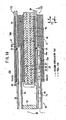
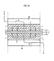
- the fuel cell 180 has a separator 192, wherein a deformable elastic channel member, such as an electrically conductive mesh member 196, is provided on a surface 36a of the circular disk 36 of the separator 192.
- the electrically conductive mesh member 196 forms a fuel gas channel 46 through which the fuel gas is supplied along a surface of the anode 24, wherein the electrically conductive mesh member 196 is in tight contact with the anode 24 (see FIGS. 17 and 18 ).
Landscapes
- Engineering & Computer Science (AREA)
- Chemical & Material Sciences (AREA)
- Life Sciences & Earth Sciences (AREA)
- Manufacturing & Machinery (AREA)
- Sustainable Development (AREA)
- Sustainable Energy (AREA)
- Chemical Kinetics & Catalysis (AREA)
- Electrochemistry (AREA)
- General Chemical & Material Sciences (AREA)
- Combustion & Propulsion (AREA)
- Fuel Cell (AREA)
Claims (17)
- Festoxid-Brennstoffzelle (11), die durch Stapeln einer Elektrolyt-Elektroden-Anordnung (26) und eines Separators (28) gebildet ist, wobei die Elektrolyt-Elektroden-Anordnung (26) eine Anode (24), eine Kathode (22) und einen Elektrolyten (20) umfasst, der zwischen der Anode (24) und der Kathode (22) angeordnet ist, wobei die Brennstoffzelle umfasst:einen Brenngaskanal (46), um ein Brenngas entlang einer Fläche der Anode (24) zu liefern, und der an einer Fläche des Separators (28) ausgebildet ist,einen Kanal (70) für sauerstoffhaltiges Gas, um ein sauerstoffhaltiges Gas entlang einer Fläche einer anderen Kathode (22) zu liefern, und der an der anderen Fläche des Separators (28) ausgebildet ist,einen Brenngas-Zufuhrkanal (58), der an der anderen Fläche des Separators (28) vorgesehen ist, wobei der Brenngas-Zufuhrkanal (58) mit einer Brenngas-Zufuhreinheit (32) verbunden ist, die als Durchgang für das Brenngas vor dem Verbrauch dient und sich in eine Stapelrichtung erstreckt, und er weiter mit einem Brenngas-Einlass (38) verbunden ist, um das Brenngas in den Brenngaskanal (46) zuzuführen,eine Zufuhreinheit (74) für sauerstoffhaltiges Gas, die als Durchgang für das sauerstoffhaltige Gas vor dem Verbrauch dient und sich in die Stapelrichtung erstreckt, um dem Kanal (70) für sauerstoffhaltiges Gas das sauerstoffhaltige Gas zuzuführen, undein Kanalelement (60), welches in Kontakt mit der anderen Fläche des Separators (28) steht und den Brenngas-Zufuhrkanal (58) und eine Ausgabe-Rille (59a) abdeckt, die an der anderen Fläche des Separators (28) vorgesehen ist,wobei der Brenngaskanal (46) einen Endpunkt an einer Position aufweist, welche einem Außenumfangs-Abschnitt der Elektrolyt-Elektroden-Anordnung (26) entspricht, und der Endpunkt des Brenngaskanals (46) mit einem Brenngas-Ausgabekanal (61) verbunden ist, um das innerhalb der Elektrolyt-Elektroden-Anordnung (26) verbrauchte Brenngas zu der Zufuhreinheit (74) für sauerstoffhaltiges Gas von einer Position auszugeben, die nach außen von einem Außenumfang der Elektrolyt-Elektroden-Anordnung (26) beabstandet ist, undwobei der Brenngas-Ausgabekanal (61) ein sich durch den Separator (28) hindurch erstreckendes Durchgangsloch (54a) und die Ausgabe-Rille (59a) umfasst, wobei die Ausgabe-Rille (59a) mit dem Durchgangsloch (54) verbunden ist, sich von der Elektrolyt-Elektroden-Anordnung (26) aus nach außen erstreckt und zu der Zufuhreinheit (74) für sauerstoffhaltiges Gas hin öffnet.
- Festoxid-Brennstoffzelle nach Anspruch 1, wobei der Brenngaskanal (46) eine Kanaleinheit (48a) umfasst, die an der einen Fläche des Separators (28) vorgesehen ist, wobei die Kanaleinheit (48a) von dem Brenngas-Einlass (38) aus mit dem Brenngas-Ausgabekanal (61) verbunden ist.
- Festoxid-Brennstoffzelle nach Anspruch 1, weiter umfassend einen ringförmigen Vorsprung (56), der an der einen Fläche des Separators (28) in engem Kontakt mit einem Außenumfangs-Abschnitt der Anode (24) vorgesehen ist.
- Festoxid-Brennstoffzelle nach Anspruch 2, wobei die Kanaleinheit eine Rille (48a) umfasst.
- Festoxid-Brennstoffzelle nach Anspruch 2, wobei die Kanaleinheit eine Mehrzahl von Vorsprüngen (186) umfasst.
- Festoxid-Brennstoffzelle nach Anspruch 2, wobei die Kanaleinheit ein verformbares elastisches Kanalelement (196) in engem Kontakt mit der Anode (24) umfasst.
- Festoxid-Brennstoffzelle nach Anspruch 1, wobei der Kanal (70) für sauerstoffhaltiges Gas ein verformbares elastisches Kanalelement (72) umfasst, das an der anderen Fläche des Separators (28) in engem Kontakt mit der anderen Kathode (22) vorgesehen ist.
- Festoxid-Brennstoffzelle nach Anspruch 7, wobei ein Bereich, in welchem das elastische Kanalelement (72) angeordnet ist, kleiner ist als ein Energie-Erzeugung-Bereich der Anode (24).
- Festoxid-Brennstoffzelle nach Anspruch 8, wobei das elastische Kanalelement (72) ein elektrisch leitendes Netz-Element oder ein Filz-Element umfasst.
- Festoxid-Brennstoffzelle nach Anspruch 1, wobei der Kanal (70) für sauerstoffhaltiges Gas eine Mehrzahl von Vorsprüngen (146) umfasst, die an der anderen Fläche des Separators (142) vorgesehen sind.
- Festoxid-Brennstoffzelle nach Anspruch 10, wobei die Vorsprünge (146) eine Mehrzahl von festen Abschnitten umfassen, die durch Ätzen an einer Fläche des Separators (142) gebildet sind.
- Brennstoffzellenstapel, der durch Stapeln einer Mehrzahl von Festoxid-Brennstoffzellen nach Anspruch 1 gebildet ist, weiter umfassend:einen Abgaskanal (78) um ein Reaktionsgas als Abgas nach einem Verbrauch in einer Reaktion in der Elektrolyt-Elektroden-Anordnung (26) in der Stapelrichtung der Elektrolyt-Elektroden-Anordnung (26) und des Separators (28) abzugeben,wobei die Brenngas-Zufuhreinheit (32) hermetisch innerhalb der Zufuhreinheit (74) für sauerstoffhaltiges Gas angeordnet ist, undwobei der Brenngas-Zufuhrkanal (58) den Brenngaskanal (46) und die Brenngas-Zufuhreinheit (32) verbindet und längs der Separator-Fläche angeordnet ist, so dass er die Zufuhreinheit (74) für sauerstoffhaltiges Gas schneidet, welche sich in die Stapelrichtung erstreckt.
- Brennstoffzellenstapel nach Anspruch 12, wobei der Abgaskanal (78) um den Separator (28) herum angeordnet ist.
- Brennstoffzellenstapel nach Anspruch 12, wobei die Brenngas-Zufuhreinheit (32) hermetisch an einem mittleren Bereich des Separators (28) angeordnet ist, und die Zufuhreinheit (74)für sauerstoffhaltiges Gas in einem inneren Bereich des Separators (28) angeordnet ist.
- Brennstoffzellenstapel nach Anspruch 12, wobei der Brenngas-Einlass (38) an einem mittleren Abschnitt der Elektrolyt-Elektroden Anordnung (26) angeordnet ist.
- Festoxid-Brennstoffzelle nach Anspruch 1, wobei die Elektrolyt-Elektroden-Anordnung (26) eine Mehrzahl von Elektrolyt-ElektrodenAnordnungen umfasst, die konzentrisch um einen Mittelpunkt des Separators (28) angeordnet sind.
- Brennstoffzellenstapel, der durch Stapeln einer Mehrzahl von Festoxid-Brennstoffzellen (11) nach einem der Ansprüche 1 bis 11 oder 16 gebildet ist.
Applications Claiming Priority (2)
| Application Number | Priority Date | Filing Date | Title |
|---|---|---|---|
| JP2005378494A JP4611196B2 (ja) | 2005-12-28 | 2005-12-28 | 燃料電池及び燃料電池スタック |
| PCT/JP2006/325121 WO2007077724A1 (en) | 2005-12-28 | 2006-12-11 | Fuel cell and fuel cell stack |
Publications (2)
| Publication Number | Publication Date |
|---|---|
| EP1969660A1 EP1969660A1 (de) | 2008-09-17 |
| EP1969660B1 true EP1969660B1 (de) | 2012-03-07 |
Family
ID=37872160
Family Applications (1)
| Application Number | Title | Priority Date | Filing Date |
|---|---|---|---|
| EP06834848A Not-in-force EP1969660B1 (de) | 2005-12-28 | 2006-12-11 | Brennstoffzelle und brennstoffzellenstapel |
Country Status (7)
| Country | Link |
|---|---|
| US (1) | US8039169B2 (de) |
| EP (1) | EP1969660B1 (de) |
| JP (1) | JP4611196B2 (de) |
| KR (1) | KR20080072091A (de) |
| CN (1) | CN101351919A (de) |
| AU (1) | AU2006333901A1 (de) |
| WO (1) | WO2007077724A1 (de) |
Families Citing this family (14)
| Publication number | Priority date | Publication date | Assignee | Title |
|---|---|---|---|---|
| JP4611194B2 (ja) * | 2005-12-28 | 2011-01-12 | 本田技研工業株式会社 | 燃料電池及び燃料電池スタック |
| JP5111810B2 (ja) * | 2006-08-15 | 2013-01-09 | 本田技研工業株式会社 | 燃料電池 |
| JP5202902B2 (ja) * | 2007-08-13 | 2013-06-05 | 本田技研工業株式会社 | 燃料電池の製造方法 |
| US8507145B2 (en) | 2007-08-13 | 2013-08-13 | Honda Motor Co., Ltd. | Fuel cell and method of producing the fuel cell |
| JP2009170342A (ja) * | 2008-01-18 | 2009-07-30 | Honda Motor Co Ltd | 燃料電池 |
| JP5283210B2 (ja) * | 2008-01-18 | 2013-09-04 | 本田技研工業株式会社 | 燃料電池 |
| JP5341599B2 (ja) * | 2009-04-02 | 2013-11-13 | 本田技研工業株式会社 | 燃料電池 |
| JP5341600B2 (ja) | 2009-04-02 | 2013-11-13 | 本田技研工業株式会社 | 燃料電池 |
| CN101860280B (zh) * | 2010-04-27 | 2012-07-25 | 南京航空航天大学 | 微小型燃烧式半导体温差发电机 |
| JP5675437B2 (ja) | 2011-03-02 | 2015-02-25 | 本田技研工業株式会社 | 燃料電池スタック |
| JP5756653B2 (ja) * | 2011-03-02 | 2015-07-29 | 本田技研工業株式会社 | 燃料電池スタック |
| JP5789533B2 (ja) * | 2012-01-30 | 2015-10-07 | 本田技研工業株式会社 | 燃料電池モジュール |
| CN106207241B (zh) * | 2016-08-03 | 2018-06-12 | 华中科技大学 | 一种固体氧化物燃料电池多堆集成结构 |
| TWI665818B (zh) * | 2018-03-29 | 2019-07-11 | National Chin-Yi University Of Technology | 圓盤型燃料電池結構 |
Family Cites Families (27)
| Publication number | Priority date | Publication date | Assignee | Title |
|---|---|---|---|---|
| JPH05135795A (ja) | 1991-11-08 | 1993-06-01 | Tokyo Gas Co Ltd | 固体電解質型燃料電池 |
| JPH0845516A (ja) * | 1994-07-29 | 1996-02-16 | Tokyo Gas Co Ltd | 線径の異なるメッシュを用いた平板型固体電解質燃料電池 |
| US6083636A (en) * | 1994-08-08 | 2000-07-04 | Ztek Corporation | Fuel cell stacks for ultra-high efficiency power systems |
| JP3229827B2 (ja) * | 1997-02-17 | 2001-11-19 | 有限会社西原工器 | 燃料電池用セパレータ |
| JP2000323154A (ja) * | 1999-05-13 | 2000-11-24 | Mitsubishi Materials Corp | 平板式燃料電池 |
| US6569554B1 (en) * | 1999-07-28 | 2003-05-27 | Sulzer Hexis Ag | Fuel cell battery with a stack of planar cells |
| JP4809519B2 (ja) * | 1999-09-10 | 2011-11-09 | 本田技研工業株式会社 | 燃料電池 |
| US7226688B2 (en) * | 1999-09-10 | 2007-06-05 | Honda Motor Co., Ltd. | Fuel cell |
| US6440596B1 (en) * | 1999-10-20 | 2002-08-27 | Technology Management, Inc. | Solid-oxide fuel cell hot assembly |
| JP2001223014A (ja) * | 2000-02-09 | 2001-08-17 | Mitsubishi Nuclear Fuel Co Ltd | 固体電解質型燃料電池 |
| JP2002151106A (ja) * | 2000-11-10 | 2002-05-24 | Sumitomo Precision Prod Co Ltd | 燃料電池 |
| JP2002203588A (ja) * | 2000-12-28 | 2002-07-19 | Mitsubishi Materials Corp | 固体酸化物型燃料電池 |
| JP2002289248A (ja) * | 2001-01-17 | 2002-10-04 | Nissan Motor Co Ltd | 燃料電池用単セル及び固体電解質型燃料電池 |
| JP2003163016A (ja) * | 2001-09-13 | 2003-06-06 | Ngk Insulators Ltd | 電気化学装置および電気化学装置用導電性接続部材 |
| US6942940B2 (en) * | 2002-05-03 | 2005-09-13 | Gas Research Institute | System for generating electricity |
| WO2004004038A2 (en) * | 2002-06-28 | 2004-01-08 | Honda Giken Kogyo Kabushiki Kaisha | Fuel cell and fuel cell stack |
| JP4394899B2 (ja) * | 2002-08-28 | 2010-01-06 | 本田技研工業株式会社 | 燃料電池 |
| JP4394865B2 (ja) * | 2002-06-28 | 2010-01-06 | 本田技研工業株式会社 | 燃料電池 |
| JP4404331B2 (ja) * | 2003-02-27 | 2010-01-27 | 住友精密工業株式会社 | 燃料電池 |
| JP2004362990A (ja) * | 2003-06-05 | 2004-12-24 | Honda Motor Co Ltd | 燃料電池 |
| JP4300947B2 (ja) | 2003-09-05 | 2009-07-22 | 三菱マテリアル株式会社 | 固体酸化物形燃料電池 |
| JP4529393B2 (ja) * | 2003-09-05 | 2010-08-25 | 三菱マテリアル株式会社 | 固体酸化物形燃料電池 |
| JP4322106B2 (ja) * | 2003-12-17 | 2009-08-26 | 本田技研工業株式会社 | 燃料電池及び燃料電池スタック |
| JP4351619B2 (ja) * | 2003-12-26 | 2009-10-28 | 本田技研工業株式会社 | 燃料電池 |
| JP4643923B2 (ja) | 2004-04-05 | 2011-03-02 | 本田技研工業株式会社 | 燃料電池及び燃料電池スタック |
| JP2006179285A (ja) * | 2004-12-22 | 2006-07-06 | Honda Motor Co Ltd | 燃料電池システム |
| JP2006318857A (ja) * | 2005-05-16 | 2006-11-24 | Honda Motor Co Ltd | 燃料電池及び燃料電池スタック |
-
2005
- 2005-12-28 JP JP2005378494A patent/JP4611196B2/ja not_active Expired - Fee Related
-
2006
- 2006-12-11 WO PCT/JP2006/325121 patent/WO2007077724A1/en not_active Ceased
- 2006-12-11 CN CNA2006800498203A patent/CN101351919A/zh active Pending
- 2006-12-11 AU AU2006333901A patent/AU2006333901A1/en not_active Abandoned
- 2006-12-11 EP EP06834848A patent/EP1969660B1/de not_active Not-in-force
- 2006-12-11 KR KR1020087015870A patent/KR20080072091A/ko not_active Ceased
- 2006-12-11 US US12/159,148 patent/US8039169B2/en not_active Expired - Fee Related
Also Published As
| Publication number | Publication date |
|---|---|
| US8039169B2 (en) | 2011-10-18 |
| EP1969660A1 (de) | 2008-09-17 |
| AU2006333901A1 (en) | 2007-07-12 |
| CN101351919A (zh) | 2009-01-21 |
| US20090311573A1 (en) | 2009-12-17 |
| WO2007077724A1 (en) | 2007-07-12 |
| JP4611196B2 (ja) | 2011-01-12 |
| JP2007179926A (ja) | 2007-07-12 |
| KR20080072091A (ko) | 2008-08-05 |
Similar Documents
| Publication | Publication Date | Title |
|---|---|---|
| US8137851B2 (en) | Fuel cell and fuel cell module | |
| EP1969660B1 (de) | Brennstoffzelle und brennstoffzellenstapel | |
| EP1969659B9 (de) | Brennstoffzelle und brennstoffzellenstapel | |
| US8273492B2 (en) | Load applying mechanism in a fuel cell system | |
| US8168341B2 (en) | Fuel cell and fuel cell stack | |
| KR100853977B1 (ko) | 연료 전지 시스템 | |
| US7875401B2 (en) | Fuel cell system | |
| US8247133B2 (en) | Fuel cell | |
| US7871730B2 (en) | Fuel cell and fuel cell stack having a filter mechanism | |
| US20060292433A1 (en) | Fuel cell and fuel cell stack | |
| US20070065710A1 (en) | Fuel Cell |
Legal Events
| Date | Code | Title | Description |
|---|---|---|---|
| PUAI | Public reference made under article 153(3) epc to a published international application that has entered the european phase |
Free format text: ORIGINAL CODE: 0009012 |
|
| 17P | Request for examination filed |
Effective date: 20080626 |
|
| AK | Designated contracting states |
Kind code of ref document: A1 Designated state(s): AT BE BG CH CY CZ DE DK EE ES FI FR GB GR HU IE IS IT LI LT LU LV MC NL PL PT RO SE SI SK TR |
|
| 17Q | First examination report despatched |
Effective date: 20090915 |
|
| GRAP | Despatch of communication of intention to grant a patent |
Free format text: ORIGINAL CODE: EPIDOSNIGR1 |
|
| GRAS | Grant fee paid |
Free format text: ORIGINAL CODE: EPIDOSNIGR3 |
|
| GRAA | (expected) grant |
Free format text: ORIGINAL CODE: 0009210 |
|
| AK | Designated contracting states |
Kind code of ref document: B1 Designated state(s): AT BE BG CH CY CZ DE DK EE ES FI FR GB GR HU IE IS IT LI LT LU LV MC NL PL PT RO SE SI SK TR |
|
| DAX | Request for extension of the european patent (deleted) | ||
| REG | Reference to a national code |
Ref country code: GB Ref legal event code: FG4D |
|
| REG | Reference to a national code |
Ref country code: CH Ref legal event code: EP Ref country code: AT Ref legal event code: REF Ref document number: 548772 Country of ref document: AT Kind code of ref document: T Effective date: 20120315 |
|
| REG | Reference to a national code |
Ref country code: IE Ref legal event code: FG4D |
|
| REG | Reference to a national code |
Ref country code: DE Ref legal event code: R096 Ref document number: 602006028105 Country of ref document: DE Effective date: 20120503 |
|
| REG | Reference to a national code |
Ref country code: NL Ref legal event code: VDEP Effective date: 20120307 |
|
| PG25 | Lapsed in a contracting state [announced via postgrant information from national office to epo] |
Ref country code: LT Free format text: LAPSE BECAUSE OF FAILURE TO SUBMIT A TRANSLATION OF THE DESCRIPTION OR TO PAY THE FEE WITHIN THE PRESCRIBED TIME-LIMIT Effective date: 20120307 Ref country code: NL Free format text: LAPSE BECAUSE OF FAILURE TO SUBMIT A TRANSLATION OF THE DESCRIPTION OR TO PAY THE FEE WITHIN THE PRESCRIBED TIME-LIMIT Effective date: 20120307 |
|
| LTIE | Lt: invalidation of european patent or patent extension |
Effective date: 20120307 |
|
| PG25 | Lapsed in a contracting state [announced via postgrant information from national office to epo] |
Ref country code: GR Free format text: LAPSE BECAUSE OF FAILURE TO SUBMIT A TRANSLATION OF THE DESCRIPTION OR TO PAY THE FEE WITHIN THE PRESCRIBED TIME-LIMIT Effective date: 20120608 Ref country code: LV Free format text: LAPSE BECAUSE OF FAILURE TO SUBMIT A TRANSLATION OF THE DESCRIPTION OR TO PAY THE FEE WITHIN THE PRESCRIBED TIME-LIMIT Effective date: 20120307 Ref country code: FI Free format text: LAPSE BECAUSE OF FAILURE TO SUBMIT A TRANSLATION OF THE DESCRIPTION OR TO PAY THE FEE WITHIN THE PRESCRIBED TIME-LIMIT Effective date: 20120307 |
|
| REG | Reference to a national code |
Ref country code: AT Ref legal event code: MK05 Ref document number: 548772 Country of ref document: AT Kind code of ref document: T Effective date: 20120307 |
|
| PG25 | Lapsed in a contracting state [announced via postgrant information from national office to epo] |
Ref country code: CY Free format text: LAPSE BECAUSE OF FAILURE TO SUBMIT A TRANSLATION OF THE DESCRIPTION OR TO PAY THE FEE WITHIN THE PRESCRIBED TIME-LIMIT Effective date: 20120307 |
|
| PG25 | Lapsed in a contracting state [announced via postgrant information from national office to epo] |
Ref country code: PL Free format text: LAPSE BECAUSE OF FAILURE TO SUBMIT A TRANSLATION OF THE DESCRIPTION OR TO PAY THE FEE WITHIN THE PRESCRIBED TIME-LIMIT Effective date: 20120307 Ref country code: SE Free format text: LAPSE BECAUSE OF FAILURE TO SUBMIT A TRANSLATION OF THE DESCRIPTION OR TO PAY THE FEE WITHIN THE PRESCRIBED TIME-LIMIT Effective date: 20120307 Ref country code: SI Free format text: LAPSE BECAUSE OF FAILURE TO SUBMIT A TRANSLATION OF THE DESCRIPTION OR TO PAY THE FEE WITHIN THE PRESCRIBED TIME-LIMIT Effective date: 20120307 Ref country code: CZ Free format text: LAPSE BECAUSE OF FAILURE TO SUBMIT A TRANSLATION OF THE DESCRIPTION OR TO PAY THE FEE WITHIN THE PRESCRIBED TIME-LIMIT Effective date: 20120307 Ref country code: EE Free format text: LAPSE BECAUSE OF FAILURE TO SUBMIT A TRANSLATION OF THE DESCRIPTION OR TO PAY THE FEE WITHIN THE PRESCRIBED TIME-LIMIT Effective date: 20120307 Ref country code: BE Free format text: LAPSE BECAUSE OF FAILURE TO SUBMIT A TRANSLATION OF THE DESCRIPTION OR TO PAY THE FEE WITHIN THE PRESCRIBED TIME-LIMIT Effective date: 20120307 Ref country code: RO Free format text: LAPSE BECAUSE OF FAILURE TO SUBMIT A TRANSLATION OF THE DESCRIPTION OR TO PAY THE FEE WITHIN THE PRESCRIBED TIME-LIMIT Effective date: 20120307 Ref country code: IS Free format text: LAPSE BECAUSE OF FAILURE TO SUBMIT A TRANSLATION OF THE DESCRIPTION OR TO PAY THE FEE WITHIN THE PRESCRIBED TIME-LIMIT Effective date: 20120707 |
|
| PG25 | Lapsed in a contracting state [announced via postgrant information from national office to epo] |
Ref country code: PT Free format text: LAPSE BECAUSE OF FAILURE TO SUBMIT A TRANSLATION OF THE DESCRIPTION OR TO PAY THE FEE WITHIN THE PRESCRIBED TIME-LIMIT Effective date: 20120709 Ref country code: SK Free format text: LAPSE BECAUSE OF FAILURE TO SUBMIT A TRANSLATION OF THE DESCRIPTION OR TO PAY THE FEE WITHIN THE PRESCRIBED TIME-LIMIT Effective date: 20120307 |
|
| PLBE | No opposition filed within time limit |
Free format text: ORIGINAL CODE: 0009261 |
|
| STAA | Information on the status of an ep patent application or granted ep patent |
Free format text: STATUS: NO OPPOSITION FILED WITHIN TIME LIMIT |
|
| PG25 | Lapsed in a contracting state [announced via postgrant information from national office to epo] |
Ref country code: DK Free format text: LAPSE BECAUSE OF FAILURE TO SUBMIT A TRANSLATION OF THE DESCRIPTION OR TO PAY THE FEE WITHIN THE PRESCRIBED TIME-LIMIT Effective date: 20120307 Ref country code: AT Free format text: LAPSE BECAUSE OF FAILURE TO SUBMIT A TRANSLATION OF THE DESCRIPTION OR TO PAY THE FEE WITHIN THE PRESCRIBED TIME-LIMIT Effective date: 20120307 |
|
| 26N | No opposition filed |
Effective date: 20121210 |
|
| PG25 | Lapsed in a contracting state [announced via postgrant information from national office to epo] |
Ref country code: IT Free format text: LAPSE BECAUSE OF FAILURE TO SUBMIT A TRANSLATION OF THE DESCRIPTION OR TO PAY THE FEE WITHIN THE PRESCRIBED TIME-LIMIT Effective date: 20120307 |
|
| REG | Reference to a national code |
Ref country code: DE Ref legal event code: R097 Ref document number: 602006028105 Country of ref document: DE Effective date: 20121210 |
|
| PG25 | Lapsed in a contracting state [announced via postgrant information from national office to epo] |
Ref country code: ES Free format text: LAPSE BECAUSE OF FAILURE TO SUBMIT A TRANSLATION OF THE DESCRIPTION OR TO PAY THE FEE WITHIN THE PRESCRIBED TIME-LIMIT Effective date: 20120618 |
|
| PG25 | Lapsed in a contracting state [announced via postgrant information from national office to epo] |
Ref country code: BG Free format text: LAPSE BECAUSE OF FAILURE TO SUBMIT A TRANSLATION OF THE DESCRIPTION OR TO PAY THE FEE WITHIN THE PRESCRIBED TIME-LIMIT Effective date: 20120607 Ref country code: MC Free format text: LAPSE BECAUSE OF NON-PAYMENT OF DUE FEES Effective date: 20121231 |
|
| REG | Reference to a national code |
Ref country code: CH Ref legal event code: PL |
|
| REG | Reference to a national code |
Ref country code: IE Ref legal event code: MM4A |
|
| REG | Reference to a national code |
Ref country code: FR Ref legal event code: ST Effective date: 20130830 |
|
| PG25 | Lapsed in a contracting state [announced via postgrant information from national office to epo] |
Ref country code: CH Free format text: LAPSE BECAUSE OF NON-PAYMENT OF DUE FEES Effective date: 20121231 Ref country code: LI Free format text: LAPSE BECAUSE OF NON-PAYMENT OF DUE FEES Effective date: 20121231 Ref country code: IE Free format text: LAPSE BECAUSE OF NON-PAYMENT OF DUE FEES Effective date: 20121211 |
|
| PG25 | Lapsed in a contracting state [announced via postgrant information from national office to epo] |
Ref country code: FR Free format text: LAPSE BECAUSE OF NON-PAYMENT OF DUE FEES Effective date: 20130102 |
|
| PG25 | Lapsed in a contracting state [announced via postgrant information from national office to epo] |
Ref country code: TR Free format text: LAPSE BECAUSE OF FAILURE TO SUBMIT A TRANSLATION OF THE DESCRIPTION OR TO PAY THE FEE WITHIN THE PRESCRIBED TIME-LIMIT Effective date: 20120307 |
|
| PG25 | Lapsed in a contracting state [announced via postgrant information from national office to epo] |
Ref country code: LU Free format text: LAPSE BECAUSE OF NON-PAYMENT OF DUE FEES Effective date: 20121211 |
|
| PG25 | Lapsed in a contracting state [announced via postgrant information from national office to epo] |
Ref country code: HU Free format text: LAPSE BECAUSE OF FAILURE TO SUBMIT A TRANSLATION OF THE DESCRIPTION OR TO PAY THE FEE WITHIN THE PRESCRIBED TIME-LIMIT Effective date: 20061211 |
|
| REG | Reference to a national code |
Ref country code: DE Ref legal event code: R084 Ref document number: 602006028105 Country of ref document: DE |
|
| REG | Reference to a national code |
Ref country code: GB Ref legal event code: 746 Effective date: 20191217 |
|
| PGFP | Annual fee paid to national office [announced via postgrant information from national office to epo] |
Ref country code: GB Payment date: 20191213 Year of fee payment: 14 |
|
| PGFP | Annual fee paid to national office [announced via postgrant information from national office to epo] |
Ref country code: DE Payment date: 20201201 Year of fee payment: 15 |
|
| GBPC | Gb: european patent ceased through non-payment of renewal fee |
Effective date: 20201211 |
|
| PG25 | Lapsed in a contracting state [announced via postgrant information from national office to epo] |
Ref country code: GB Free format text: LAPSE BECAUSE OF NON-PAYMENT OF DUE FEES Effective date: 20201211 |
|
| REG | Reference to a national code |
Ref country code: DE Ref legal event code: R119 Ref document number: 602006028105 Country of ref document: DE |
|
| PG25 | Lapsed in a contracting state [announced via postgrant information from national office to epo] |
Ref country code: DE Free format text: LAPSE BECAUSE OF NON-PAYMENT OF DUE FEES Effective date: 20220701 |