EP1969916B1 - System und Verfahren zur Lenkung eines Nutzfahrzeugs zum Schleppen einer Schleppvorrichtung auf seitlichen Steigungen - Google Patents
System und Verfahren zur Lenkung eines Nutzfahrzeugs zum Schleppen einer Schleppvorrichtung auf seitlichen Steigungen Download PDFInfo
- Publication number
- EP1969916B1 EP1969916B1 EP08102285A EP08102285A EP1969916B1 EP 1969916 B1 EP1969916 B1 EP 1969916B1 EP 08102285 A EP08102285 A EP 08102285A EP 08102285 A EP08102285 A EP 08102285A EP 1969916 B1 EP1969916 B1 EP 1969916B1
- Authority
- EP
- European Patent Office
- Prior art keywords
- steering
- slope
- implement
- offset compensation
- compensation value
- Prior art date
- Legal status (The legal status is an assumption and is not a legal conclusion. Google has not performed a legal analysis and makes no representation as to the accuracy of the status listed.)
- Ceased
Links
Images
Classifications
-
- A—HUMAN NECESSITIES
- A01—AGRICULTURE; FORESTRY; ANIMAL HUSBANDRY; HUNTING; TRAPPING; FISHING
- A01B—SOIL WORKING IN AGRICULTURE OR FORESTRY; PARTS, DETAILS, OR ACCESSORIES OF AGRICULTURAL MACHINES OR IMPLEMENTS, IN GENERAL
- A01B69/00—Steering of agricultural machines or implements; Guiding agricultural machines or implements on a desired track
- A01B69/007—Steering or guiding of agricultural vehicles, e.g. steering of the tractor to keep the plough in the furrow
- A01B69/008—Steering or guiding of agricultural vehicles, e.g. steering of the tractor to keep the plough in the furrow automatic
Definitions
- the present invention relates to automatic steering of work vehicles, in particular agricultural vehicles with towed implements.
- GPS global positioning system
- a steering system, a work vehicle and a method for automatically steering a work vehicle towing an implement are proposed.
- the steering system comprises a location signal generation arrangement for providing location data of the position of the vehicle in a field. Desired path data representing a desired path of the implement over the field are stored in memory. The desired path can be straight or curved or a combination of straight and curved sections.
- a slope data provision arrangement provides a lateral inclination value of at least one of the work vehicle or the implement.
- a steering control unit is coupled to the location signal generation arrangement, the memory and the slope data provision arrangement and provides steering data.
- the steering control unit calculates a lateral offset compensation value based upon the location data from the location signal generation arrangement and the desired path data from memory.
- This lateral offset compensation value is calculated such that the work vehicle would be steered using this value in a manner such that the implement is moved on the desired path.
- the lateral compensation offset value takes a possible lateral deviation between the position sensed by the location signal generation arrangement and the desired path into account, as well as a possible curvature of the path and the geometry and kinematics of the tractor/implement combination. Reference is made to WO 2008/005195 A , the disclosure of which incorporated herein by reference.
- the steering control unit further calculates a slope offset compensation value based upon the lateral inclination value from the slope data provision arrangement.
- the slope offset compensation value compensates for gravity forces pulling the implement down a lateral slope.
- a steering signal is based upon the lateral offset compensation value and the slope offset compensation value.
- the steering control unit applies a lateral offset compensation to the location data based upon the signal from the slope data provision arrangement.
- a steering actuator is provided to control the propelling direction of the work vehicle that receives a steering signal from the steering control unit.
- the steering actuator can control the steering angle of steerable wheels of the vehicle or the speed of tracks of a tracked vehicle, which are driven with different speeds to perform a steering operation.
- a display unit receives the steering signal and displays to an operator in which direction he or she should steer.
- the location signal generation arrangement preferably comprises an antenna for
- the location signal generation arrangement preferably comprises an antenna for receiving signals from a satellite based location system like the Global Positioning System (GPS), Glonass or Galileo, and/or a local sensor interacting with features of the field, like rows that may consist of cut crop or standing crop or edges between cut and uncut crop or raised dams on the field.
- the local sensor can be a mechanical feeler, an ultrasonic or optical distance sensor, a runtime based laser scanner, a camera with an image processing system, or some other arrangement of one or more sensors.
- the slope data provision arrangement preferably comprises a slope sensor detecting a lateral inclination of the work vehicle and/or the implement.
- a lateral slope value is derived from a topographical database based upon the location signal.
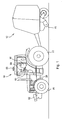
- a side view of a self propelled work vehicle 10 in the form of a tractor and an implement 12 towed by the tractor is shown.
- the implement 12 is a round baler; however, it can be appreciated that any one of a variety of agricultural implements can be used.
- the vehicle 10 comprises a frame 26 supported on steerable front wheels 20 and driven rear wheels 22.
- a steering wheel 32 is provided in a cab 30 on the frame 26, a steering wheel 32 is provided.
- a steering actuator 36 in the form of a hydraulic cylinder is mounted between the frame 26 and a steering rod 38 connecting to the front wheels 20.
- the front wheels 20 are pivotally supported on a front axle 42 around a vertical rotation axis.
- the steering actuator 36 can thus define the forward direction of the vehicle 10.
- Steering actuator 36 is connected to an electromagnetic valve assembly 44, which is electrically connected to a steering controller 46.
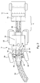
- the steering controller 46 is additionally connected to a first location signal generation arrangement 50 in the form of an antenna receiving signals from a satellite positioning system that is mounted upon the roof of the cab 30.
- the steering controller 46 is also connected to a second location signal generation arrangement 52 in the form of an electronic video camera mounted at the front of the vehicle 10.
- the second location signal generation arrangement 52 comprises an image processing system recognizing the location of a grain swath 56 on the field.
- Steering controller 46 is further connected to a display 58 in the cab 30 and to a user interface 60.
- the user interface 60 in this arrangement comprises a keyboard and switches.
- the steering controller 46 holds desired path data representing a desired path of the implement 12 over the field in an electronic memory device (memory).
- the path data comprises straight and curved segments and have been collected during the previous operations on the field.
- the desired path data corresponds in this example to the position of the swath 56.
- the steering control unit 46 is further electronically connected to a slope data provision arrangement in the form of a slope sensor 64 providing a lateral inclination value (sometimes referred to as a roll angle or tilt angle) of the work vehicle 10.
- the slope sensor 64 can comprise a pendulum connected to a potentiometer, or a gyroscope, or any other suitable sensor.
- the slope angle is also named roll angle or tilt angle.
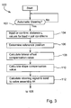
- the steering controller 46 proceeds according to the flow diagram 100 of Figure 3 .
- step 102 the steering controller 46 inquires whether the operator has selected an automatic steering mode (by means of the user interface 60). If no automatic steering mode was selected, the steering controller begins the flow diagram again. Automatic steering is also automatically stopped if the operator rotates the steering wheel 32. During manual steering, signals from a sensor (not shown) detecting the rotational position of the steering wheel 32 are sent to valve assembly 44 from the steering control unit 46.
- step 104 the operator is asked to input a value for length L that corresponds to the distance between a hitch point 68 at the rear of the work vehicle 10 and an active portion 70 of the implement 12, which in this embodiment is the pick-up of the baler. Further, the operator is asked to input information on soil and load conditions. Thus, the operator can input an estimated value for the weight of the implement and a select a type of soil condition, for example between dry, wet and extremely wet. It would also be possible to start with default, average values for load and soil conditions and let the operator input later, during operation, whether the steering reaction (gain) on a lateral slope is appropriate or should be increased or decreased. If values have already been inputted during a previous operation, the operator can simply confirm them.
- a lateral offset compensation value is calculated based upon the actual position of the reference point from step 106 and the desired path data from memory.
- This lateral offset compensation value is calculated such that the work vehicle 10 would be steered using this value in a manner such that the implement 12 (in particular the active portion 70 thereof) is moved on the desired, stored path.
- the lateral compensation offset value takes a possible lateral deviation between the actual position of the reference point from step 106 and the desired path into account, as well as a possible curvature of the path and the geometry and kinematics of the tractor/implement combination, including the length L input in step 104.
- Step 108 calculates the lateral offset compensation value for a vehicle/implement combination in a horizontal plane.
Landscapes
- Life Sciences & Earth Sciences (AREA)
- Engineering & Computer Science (AREA)
- Mechanical Engineering (AREA)
- Soil Sciences (AREA)
- Environmental Sciences (AREA)
- Guiding Agricultural Machines (AREA)
- Steering Control In Accordance With Driving Conditions (AREA)
- Automobile Manufacture Line, Endless Track Vehicle, Trailer (AREA)
Claims (14)
- Lenksystem für ein Arbeitsfahrzeug (10), das ein Anhängegerät (12) zieht, umfassend:eine Positionssignalerzeugungsanordnung (50, 52) zur Bereitstellung von Positionsdaten der Position des Fahrzeugs (10) in einem Feld,eine Speichervorrichtung zum Speichern von Daten, die eine gewünschte Bahn des Geräts (12) über das Feld darstellen,eine Neigungsdatenbereitstellungsanordnung, die einen Seitenneigungswert des Arbeitsfahrzeugs (10) und/oder des Geräts (12) bereitstellt, und eine Lenksteuereinheit (46), die mit der Positionssignalerzeugungsanordnung (50, 52), dem Speicher und der Neigungsdatenbereitstellungsanordnung (64) gekoppelt ist,dadurch gekennzeichnet, dass die Lenksteuereinheit (46) dahingehend betreibbar ist, Folgendes zu berechnen:einen Seitenversatzausgleichswert auf Grundlage der Positionsdaten von der Positionssignalerzeugungsanordnung (50, 52) und der Daten für die gewünschte Bahn aus dem Speicher, wobei der Seitenversatzausgleichswert dazu berechnet wird, das Arbeitsfahrzeug (10) so zu lenken, dass das Gerät (12) auf der gewünschten Bahn bewegt wird,einen Neigungsversatzausgleichswert auf Grundlage eines Signals von der Neigungsdatenbereitstellungsanordnung, wobei der Neigungsversatzausgleichswert dazu berechnet wird, Neigungskräfte auszugleichen, die das Gerät (12) eine Seitenneigung herunter ziehen,und ein Lenksignal auf Grundlage des Seitenversatzausgleichswerts und des Neigungsversatzausgleichswerts,und dass die Lenksteuereinheit (46) dahingehend betreibbar ist, die Positionsdaten auf Grundlage des Signals von der Neigungsdatenbereitstellungsanordnung mit einem Seitenversatzausgleich zu beaufschlagen.
- Lenksystem nach Anspruch 1, wobei die Lenksteuereinheit (46) das Lenksignal an eine Anzeige (58) und/oder einen Lenkaktuator (36) sendet, der dahingehend betreibbar ist, eine Antriebsrichtung des Arbeitsfahrzeugs (10) zu steuern.
- Lenksystem nach Anspruch 1 oder 2, wobei die Lenksteuereinheit (46) dahingehend betreibbar ist, den Neigungsversatzausgleichswert auf Grundlage eines Vorwärtsabstands zwischen einem aktiven Teil des Geräts (12) und einer Anhängekupplung (68) des Arbeitsfahrzeugs (10) zu berechnen.
- Lenksystem nach Anspruch 3, wobei die Lenksteuereinheit (46) mit einer Benutzerschnittstelle (60) zur Eingabe eines Abstandswertes, der den Abstand zwischen einem aktiven Teil des Geräts (12) und einer Anhängekupplung (68) des Arbeitsfahrzeugs (10) darstellt, gekoppelt ist.
- Lenksystem nach Anspruch 4, wobei die Lenksteuereinheit (46) dahingehend betreibbar ist, den Seitenversatzausgleichswert unter Verwendung des Eingabeabstandswerts zu berechnen.
- Lenksystem nach einem der Ansprüche 1 bis 5, wobei die Lenksteuereinheit (46) dahingehend betreibbar ist, den Neigungsversatzausgleichswert auf Grundlage eines Wertes, der die Gerätelast und/oder die Bodenbedingungen darstellt, zu berechnen.
- Lenksystem nach Anspruch 6, wobei die Lenksteuereinheit mit einer Benutzerschnittstelle (60) zur Eingabe eines Wertes, der die Gerätelast und/oder die Bodenbedingungen darstellt, gekoppelt ist.
- Lenksystem nach einem der Ansprüche 1 bis 7, wobei die Lenksteuereinheit (46) dahingehend betreibbar ist, das Lenksignal auf Grundlage einer Summe des Seitenversatzausgleichswerts und des Neigungsversatzausgleichswerts zu berechnen.
- Lenksystem nach einem der Ansprüche 1 bis 8, wobei die Positionssignalerzeugungsanordnung (50) dahingehend betreibbar ist, Signale von einem satellitengestützten Positionierungssystem zu empfangen.
- Lenksystem nach einem der Ansprüche 1 bis 8, wobei die Positionssignalerzeugungsanordnung (52) dahingehend betreibbar ist, Reihen auf einem Feld zu erfassen.
- Lenksystem nach einem der Ansprüche 1 bis 10, wobei die Daten für die gewünschte Bahn Segmente einer geraden und/oder gekrümmten Bahn enthalten.
- Lenksystem nach einem der Ansprüche 1 bis 11, wobei die Neigungsdatenbereitstellungsanordnung einen Neigungssensor (64) und/oder eine Topographie-Datenbank, von denen Neigungswerte auf Grundlage der Positionsdaten abgeleitet werden, umfasst.
- Arbeitsfahrzeug (10) mit einem Anhängegerät (12), das ein Lenksystem nach einem der Ansprüche 1 bis 13 umfasst.
- Verfahren zum Lenken eines Arbeitsfahrzeugs (10), das ein Anhängegerät (12) zieht, umfassend:Speichern von Daten für die gewünschte Bahn, die eine gewünschte Bahn des Geräts (12) über ein Feld darstellen,Bereistellen von Positionsdaten der Position des Fahrzeugs (10) im Feld,Bereitstellen eines Seitenneigungswerts des Arbeitsfahrzeugs (10) und/oder des Geräts (12),Berechnen eines Seitenversatzausgleichswerts auf Grundlage der Positionsdaten und der Daten für die gewünschte Bahn, um das Arbeitsfahrzeug (10) so zu lenken, dass das Gerät (12) auf der gewünschten Bahn bewegt wird,gekennzeichnet durch Berechnen eines Neigungsversatzausgleichswerts auf Grundlage des Seitenneigungswertes zum Ausgleich von Neigungskräften, die das Gerät (12) eine Seitenneigung herunter ziehen,Berechnen eines Lenksignals auf Grundlage des Seitenversatzausgleichswertes und des Neigungsversatzausgleichswertes,und Beaufschlagen der Positionsdaten mit einem Seitenversatzausgleich auf Grundlage des Seitenneigungswertes.
Applications Claiming Priority (1)
| Application Number | Priority Date | Filing Date | Title |
|---|---|---|---|
| US11/686,990 US8565984B2 (en) | 2007-03-16 | 2007-03-16 | System and method of steering for a work vehicle towing a towed implement on lateral slopes |
Publications (2)
| Publication Number | Publication Date |
|---|---|
| EP1969916A1 EP1969916A1 (de) | 2008-09-17 |
| EP1969916B1 true EP1969916B1 (de) | 2009-12-30 |
Family
ID=39531299
Family Applications (1)
| Application Number | Title | Priority Date | Filing Date |
|---|---|---|---|
| EP08102285A Ceased EP1969916B1 (de) | 2007-03-16 | 2008-03-05 | System und Verfahren zur Lenkung eines Nutzfahrzeugs zum Schleppen einer Schleppvorrichtung auf seitlichen Steigungen |
Country Status (4)
| Country | Link |
|---|---|
| US (1) | US8565984B2 (de) |
| EP (1) | EP1969916B1 (de) |
| AT (1) | ATE453313T1 (de) |
| DE (1) | DE602008000462D1 (de) |
Cited By (1)
| Publication number | Priority date | Publication date | Assignee | Title |
|---|---|---|---|---|
| WO2024241124A1 (en) * | 2023-05-22 | 2024-11-28 | Agco International Gmbh | Implement drift compensation system and method |
Families Citing this family (32)
| Publication number | Priority date | Publication date | Assignee | Title |
|---|---|---|---|---|
| US8260499B2 (en) * | 2007-05-01 | 2012-09-04 | Deere & Company | Automatic steering system and method for a work vehicle with feedback gain dependent on a sensed payload |
| US8190364B2 (en) | 2008-06-30 | 2012-05-29 | Deere & Company | System and method for providing towed implement compensation |
| US9273968B2 (en) * | 2010-06-23 | 2016-03-01 | Aisin Aw Co., Ltd. | Track information generating device, track information generating method, and computer-readable storage medium |
| DE102010041885A1 (de) | 2010-10-01 | 2012-04-05 | Deere & Company | Kombination aus einem Zugfahrzeug und einem Gerät |
| WO2012051236A1 (en) | 2010-10-15 | 2012-04-19 | Robert Bosch Gmbh | Continuous correction for steering wheel angle offset |
| US20120283909A1 (en) * | 2011-05-03 | 2012-11-08 | Dix Peter J | System and method for positioning a vehicle with a hitch using an automatic steering system |
| US9668400B2 (en) * | 2011-07-05 | 2017-06-06 | Kongskilde Industries A/S | Automatic guidance system for pull-type agricultural implement |
| DE102011085244A1 (de) | 2011-10-26 | 2013-05-02 | Deere & Company | Anordnung zur selbsttätigen Lenkung einer Kombination aus einem selbstfahrenden Fahrzeug und einem Gerät zur Feldbearbeitung |
| US8960085B2 (en) * | 2011-11-04 | 2015-02-24 | Deere & Company | Camera for monitoring functions of a round baler |
| US9251627B2 (en) * | 2013-03-05 | 2016-02-02 | Sears Brands, L.L.C. | Removable dashboard instrument system |
| US9709969B2 (en) | 2013-03-15 | 2017-07-18 | Deere & Company | Methods and apparatus to control machine configurations |
| US10104824B2 (en) * | 2013-10-14 | 2018-10-23 | Kinze Manufacturing, Inc. | Autonomous systems, methods, and apparatus for AG based operations |
| US9374939B2 (en) | 2014-08-29 | 2016-06-28 | Deere & Company | System and method for steering of an implement on sloped ground |
| US9904290B2 (en) * | 2015-04-19 | 2018-02-27 | Deere & Company | Geometry-based monitoring and control of coupled mobile machines |
| DE102015210352A1 (de) * | 2015-06-05 | 2016-12-08 | Robert Bosch Gmbh | Steueranordnung für eine Zugmaschine, Zugmaschine mit einer Steueranordnung und Verfahren für eine Steueranordnung |
| US10188036B2 (en) | 2015-10-23 | 2019-01-29 | Carnegie Mellon University | System for evaluating agricultural material |
| US10172285B2 (en) | 2015-10-23 | 2019-01-08 | Carnegie Mellon University | System for evaluating agricultural material |
| CA3045154A1 (en) * | 2017-01-19 | 2018-07-26 | Agjunction Llc | Low cost implement positioning |
| US10351172B2 (en) | 2017-02-28 | 2019-07-16 | Brandt Agricultural Products Ltd. | Tandem steering for a grain cart |
| US10278328B2 (en) | 2017-02-28 | 2019-05-07 | Brandt Agricultural Products Ltd. | Grain cart with automatic unloading of a predetermined weight of crop material |
| US10377290B2 (en) | 2017-02-28 | 2019-08-13 | Brandt Agricultural Products Ltd. | Spout autorotate for a grain cart |
| JP7072376B2 (ja) * | 2017-12-05 | 2022-05-20 | 株式会社クボタ | 管理システム |
| US11724735B2 (en) * | 2018-12-19 | 2023-08-15 | Hl Mando Corporation | Steering control apparatus, steering control method, and steering apparatus |
| DE102019203539A1 (de) | 2019-03-15 | 2020-09-17 | Deere & Company | System zur Kontrolle eines mit einem Fahrzeug verbundenen Arbeitsgeräts |
| US11219153B2 (en) | 2019-08-29 | 2022-01-11 | Cnh Industrial America Llc | System and method for monitoring shank float |
| US11363753B2 (en) * | 2019-10-24 | 2022-06-21 | Deere & Company | Mower implement guidance system |
| US11429114B2 (en) * | 2020-02-14 | 2022-08-30 | Deere & Company | Implement control of vehicle and implement combination |
| EP4101278B1 (de) | 2021-06-07 | 2024-03-06 | Kubota Corporation | System und verfahren zur steuerung des betriebs einer arbeitsmaschine |
| DK181791B1 (en) * | 2022-08-10 | 2025-01-06 | Farmdroid Aps | Mobile field robot and method for controlling a mobile field robot |
| US12649477B2 (en) * | 2022-08-11 | 2026-06-09 | Atieva, Inc. | Estimating and correcting bias in vehicle motion control |
| US12704854B2 (en) | 2024-06-20 | 2026-08-11 | Deere & Company | Automated path parameter computation in generating a navigation path |
| DE202026101926U1 (de) | 2025-04-11 | 2026-05-28 | Deere & Company | System zur Lenkung eines landwirtschaftlichen Fahrzeugs über ein Feld mit einer Bedienerschnittstelle, die sich an verschiedene Kompensationsmodi anpasst |
Family Cites Families (35)
| Publication number | Priority date | Publication date | Assignee | Title |
|---|---|---|---|---|
| FR2240678B1 (de) * | 1973-08-14 | 1978-01-13 | Fahr Ag Maschf | |
| US4144571A (en) * | 1977-03-15 | 1979-03-13 | E-Systems, Inc. | Vehicle guidance system |
| JP3556766B2 (ja) * | 1996-05-28 | 2004-08-25 | 松下電器産業株式会社 | 道路白線検出装置 |
| US6070673A (en) | 1996-11-22 | 2000-06-06 | Case Corporation | Location based tractor control |
| US5987383C1 (en) * | 1997-04-28 | 2006-06-13 | Trimble Navigation Ltd | Form line following guidance system |
| US5995895A (en) * | 1997-07-15 | 1999-11-30 | Case Corporation | Control of vehicular systems in response to anticipated conditions predicted using predetermined geo-referenced maps |
| US5945917A (en) * | 1997-12-18 | 1999-08-31 | Rockwell International | Swathing guidance display |
| US6041582A (en) * | 1998-02-20 | 2000-03-28 | Case Corporation | System for recording soil conditions |
| US6199000B1 (en) | 1998-07-15 | 2001-03-06 | Trimble Navigation Limited | Methods and apparatus for precision agriculture operations utilizing real time kinematic global positioning system systems |
| US6501422B1 (en) * | 1998-08-19 | 2002-12-31 | Trimble Navigation, Ltd. | Precise parallel swathing guidance via satellite navigation and tilt measurement |
| US6112144A (en) * | 1998-10-01 | 2000-08-29 | Case Corporation | Field characteristic marking system |
| US6615569B1 (en) | 1999-10-05 | 2003-09-09 | Case Corporation | Control system to automatically center an agricultural harvester header |
| US6445983B1 (en) | 2000-07-07 | 2002-09-03 | Case Corporation | Sensor-fusion navigator for automated guidance of off-road vehicles |
| US6446003B1 (en) | 2000-07-12 | 2002-09-03 | Trimble Navigation Limited | Method for determining drift with a digital compass |
| US6377889B1 (en) | 2000-10-13 | 2002-04-23 | Trimble Navigation Limited | Non-linear method of guiding to arbitrary curves with adaptive feedback |
| US6643576B1 (en) | 2000-11-15 | 2003-11-04 | Integrinautics Corporation | Rapid adjustment of trajectories for land vehicles |
| US6804587B1 (en) | 2000-11-15 | 2004-10-12 | Integrinautics Corporation | Adjustment of vehicle-implement trajectories to compensate for lateral implement offset |
| US6711501B2 (en) * | 2000-12-08 | 2004-03-23 | Satloc, Llc | Vehicle navigation system and method for swathing applications |
| US6539303B2 (en) * | 2000-12-08 | 2003-03-25 | Mcclure John A. | GPS derived swathing guidance system |
| US6819780B2 (en) | 2001-02-02 | 2004-11-16 | Cnh America Llc | Method and apparatus for automatically steering a vehicle in an agricultural field using a plurality of fuzzy logic membership functions |
| US6434462B1 (en) * | 2001-06-28 | 2002-08-13 | Deere & Company | GPS control of a tractor-towed implement |
| DE10163328B4 (de) | 2001-07-30 | 2005-08-11 | Tecpharma Licensing Ag | Verabreichungsgerät mit Verdrehsicherung |
| US7142956B2 (en) * | 2004-03-19 | 2006-11-28 | Hemisphere Gps Llc | Automatic steering system and method |
| US7437230B2 (en) * | 2003-03-20 | 2008-10-14 | Hemisphere Gps Llc | Satellite based vehicle guidance control in straight and contour modes |
| US7162348B2 (en) | 2002-12-11 | 2007-01-09 | Hemisphere Gps Llc | Articulated equipment position control system and method |
| DE10303516A1 (de) | 2003-01-30 | 2004-08-12 | Amazonen-Werke H. Dreyer Gmbh & Co. Kg | Vorrichtung zum Bearbeiten und/oder Bestellen von landwirtschaftlichen Flächen |
| CA2427416C (en) | 2003-05-01 | 2010-11-16 | 101039130 Saskatchewan Ltd. | Steering device for towed implements |
| US6789014B1 (en) | 2003-05-09 | 2004-09-07 | Deere & Company | Direct modification of DGPS information with inertial measurement data |
| US6694260B1 (en) | 2003-05-09 | 2004-02-17 | Deere & Company | Inertial augmentation for GPS navigation on ground vehicles |
| US7593798B2 (en) | 2003-10-30 | 2009-09-22 | Deere & Company | Vehicular guidance system having compensation for variations in ground elevation |
| US7451030B2 (en) * | 2005-02-04 | 2008-11-11 | Novariant, Inc. | System and method for interactive selection and determination of agricultural vehicle guide paths offset from each other with varying curvature along their length |
| DE102005005761A1 (de) | 2005-02-07 | 2006-08-10 | Claas Selbstfahrende Erntemaschinen Gmbh | Landfahrzeug mit automatischer Lenkung |
| US7509199B2 (en) | 2006-06-30 | 2009-03-24 | Deere & Company | System and method for calculating instantaneous placement corrections to achieve towed implement placement on curved paths |
| US7844378B2 (en) | 2006-10-05 | 2010-11-30 | Trimble Navigation Limited | Farm apparatus having implement sidehill drift compensation |
| US8452467B2 (en) * | 2008-09-11 | 2013-05-28 | General Electric Company | System and method for verifying track database information |
-
2007
- 2007-03-16 US US11/686,990 patent/US8565984B2/en active Active
-
2008
- 2008-03-05 AT AT08102285T patent/ATE453313T1/de not_active IP Right Cessation
- 2008-03-05 DE DE602008000462T patent/DE602008000462D1/de active Active
- 2008-03-05 EP EP08102285A patent/EP1969916B1/de not_active Ceased
Cited By (1)
| Publication number | Priority date | Publication date | Assignee | Title |
|---|---|---|---|---|
| WO2024241124A1 (en) * | 2023-05-22 | 2024-11-28 | Agco International Gmbh | Implement drift compensation system and method |
Also Published As
| Publication number | Publication date |
|---|---|
| US20080228353A1 (en) | 2008-09-18 |
| US8565984B2 (en) | 2013-10-22 |
| DE602008000462D1 (de) | 2010-02-11 |
| ATE453313T1 (de) | 2010-01-15 |
| EP1969916A1 (de) | 2008-09-17 |
Similar Documents
| Publication | Publication Date | Title |
|---|---|---|
| US8565984B2 (en) | System and method of steering for a work vehicle towing a towed implement on lateral slopes | |
| EP1987710B1 (de) | Automatisches Lenksystem und Verfahren für ein Arbeitsfahrzeug mit Rückkopplung in Abhängigkeit von einer erspürten Nutzlast | |
| US6697724B2 (en) | Automatic steering system using signal quality information | |
| JP6525902B2 (ja) | 圃場作業車両 | |
| US9615501B2 (en) | Controlling the position of an agricultural implement coupled to an agricultural vehicle based upon three-dimensional topography data | |
| US7904226B2 (en) | Correction in position with hitch position sensor | |
| EP3685649B1 (de) | System und verfahren zur steuerung eines mit einem fahrzeug verbundenen gerätes | |
| JP7271416B2 (ja) | 作業車両及び作業車両の走行管理システム | |
| JP6921935B2 (ja) | 圃場作業車両 | |
| JP2023001180A (ja) | 圃場作業車両 | |
| JP2019047731A (ja) | 作業車両 | |
| AU2024204428A1 (en) | Arrangement for detecting a possible deviation of an agricultural vehicle from a target path when working on plants grown in rows, corresponding vehicle and method | |
| US11543246B1 (en) | Rear axle center locating | |
| JP7737857B2 (ja) | 作業車両 | |
| US20240344828A1 (en) | Tractor parameter calibration | |
| JP2024119075A (ja) | 作業車両 | |
| JP2024537787A (ja) | トラクタパラメータ較正 | |
| JP2018202929A (ja) | 圃場作業車の自動操舵装置 | |
| AU2021466975A1 (en) | Rear axle center locating |
Legal Events
| Date | Code | Title | Description |
|---|---|---|---|
| PUAI | Public reference made under article 153(3) epc to a published international application that has entered the european phase |
Free format text: ORIGINAL CODE: 0009012 |
|
| AK | Designated contracting states |
Kind code of ref document: A1 Designated state(s): AT BE BG CH CY CZ DE DK EE ES FI FR GB GR HR HU IE IS IT LI LT LU LV MC MT NL NO PL PT RO SE SI SK TR |
|
| AX | Request for extension of the european patent |
Extension state: AL BA MK RS |
|
| 17P | Request for examination filed |
Effective date: 20090317 |
|
| AKX | Designation fees paid |
Designated state(s): AT BE BG CH CY CZ DE DK EE ES FI FR GB GR HR HU IE IS IT LI LT LU LV MC MT NL NO PL PT RO SE SI SK TR |
|
| 17Q | First examination report despatched |
Effective date: 20090427 |
|
| GRAP | Despatch of communication of intention to grant a patent |
Free format text: ORIGINAL CODE: EPIDOSNIGR1 |
|
| GRAS | Grant fee paid |
Free format text: ORIGINAL CODE: EPIDOSNIGR3 |
|
| GRAA | (expected) grant |
Free format text: ORIGINAL CODE: 0009210 |
|
| AK | Designated contracting states |
Kind code of ref document: B1 Designated state(s): AT BE BG CH CY CZ DE DK EE ES FI FR GB GR HR HU IE IS IT LI LT LU LV MC MT NL NO PL PT RO SE SI SK TR |
|
| REG | Reference to a national code |
Ref country code: GB Ref legal event code: FG4D |
|
| REG | Reference to a national code |
Ref country code: CH Ref legal event code: EP |
|
| REG | Reference to a national code |
Ref country code: IE Ref legal event code: FG4D |
|
| REF | Corresponds to: |
Ref document number: 602008000462 Country of ref document: DE Date of ref document: 20100211 Kind code of ref document: P |
|
| PG25 | Lapsed in a contracting state [announced via postgrant information from national office to epo] |
Ref country code: NO Free format text: LAPSE BECAUSE OF FAILURE TO SUBMIT A TRANSLATION OF THE DESCRIPTION OR TO PAY THE FEE WITHIN THE PRESCRIBED TIME-LIMIT Effective date: 20100330 Ref country code: LT Free format text: LAPSE BECAUSE OF FAILURE TO SUBMIT A TRANSLATION OF THE DESCRIPTION OR TO PAY THE FEE WITHIN THE PRESCRIBED TIME-LIMIT Effective date: 20091230 Ref country code: SE Free format text: LAPSE BECAUSE OF FAILURE TO SUBMIT A TRANSLATION OF THE DESCRIPTION OR TO PAY THE FEE WITHIN THE PRESCRIBED TIME-LIMIT Effective date: 20091230 Ref country code: FI Free format text: LAPSE BECAUSE OF FAILURE TO SUBMIT A TRANSLATION OF THE DESCRIPTION OR TO PAY THE FEE WITHIN THE PRESCRIBED TIME-LIMIT Effective date: 20091230 |
|
| REG | Reference to a national code |
Ref country code: NL Ref legal event code: VDEP Effective date: 20091230 |
|
| LTIE | Lt: invalidation of european patent or patent extension |
Effective date: 20091230 |
|
| PG25 | Lapsed in a contracting state [announced via postgrant information from national office to epo] |
Ref country code: SI Free format text: LAPSE BECAUSE OF FAILURE TO SUBMIT A TRANSLATION OF THE DESCRIPTION OR TO PAY THE FEE WITHIN THE PRESCRIBED TIME-LIMIT Effective date: 20091230 Ref country code: HR Free format text: LAPSE BECAUSE OF FAILURE TO SUBMIT A TRANSLATION OF THE DESCRIPTION OR TO PAY THE FEE WITHIN THE PRESCRIBED TIME-LIMIT Effective date: 20091230 Ref country code: LV Free format text: LAPSE BECAUSE OF FAILURE TO SUBMIT A TRANSLATION OF THE DESCRIPTION OR TO PAY THE FEE WITHIN THE PRESCRIBED TIME-LIMIT Effective date: 20091230 Ref country code: PL Free format text: LAPSE BECAUSE OF FAILURE TO SUBMIT A TRANSLATION OF THE DESCRIPTION OR TO PAY THE FEE WITHIN THE PRESCRIBED TIME-LIMIT Effective date: 20091230 |
|
| PG25 | Lapsed in a contracting state [announced via postgrant information from national office to epo] |
Ref country code: AT Free format text: LAPSE BECAUSE OF FAILURE TO SUBMIT A TRANSLATION OF THE DESCRIPTION OR TO PAY THE FEE WITHIN THE PRESCRIBED TIME-LIMIT Effective date: 20091230 |
|
| PG25 | Lapsed in a contracting state [announced via postgrant information from national office to epo] |
Ref country code: RO Free format text: LAPSE BECAUSE OF FAILURE TO SUBMIT A TRANSLATION OF THE DESCRIPTION OR TO PAY THE FEE WITHIN THE PRESCRIBED TIME-LIMIT Effective date: 20091230 Ref country code: NL Free format text: LAPSE BECAUSE OF FAILURE TO SUBMIT A TRANSLATION OF THE DESCRIPTION OR TO PAY THE FEE WITHIN THE PRESCRIBED TIME-LIMIT Effective date: 20091230 Ref country code: IS Free format text: LAPSE BECAUSE OF FAILURE TO SUBMIT A TRANSLATION OF THE DESCRIPTION OR TO PAY THE FEE WITHIN THE PRESCRIBED TIME-LIMIT Effective date: 20100430 Ref country code: ES Free format text: LAPSE BECAUSE OF FAILURE TO SUBMIT A TRANSLATION OF THE DESCRIPTION OR TO PAY THE FEE WITHIN THE PRESCRIBED TIME-LIMIT Effective date: 20100410 Ref country code: EE Free format text: LAPSE BECAUSE OF FAILURE TO SUBMIT A TRANSLATION OF THE DESCRIPTION OR TO PAY THE FEE WITHIN THE PRESCRIBED TIME-LIMIT Effective date: 20091230 Ref country code: BG Free format text: LAPSE BECAUSE OF FAILURE TO SUBMIT A TRANSLATION OF THE DESCRIPTION OR TO PAY THE FEE WITHIN THE PRESCRIBED TIME-LIMIT Effective date: 20100330 |
|
| PG25 | Lapsed in a contracting state [announced via postgrant information from national office to epo] |
Ref country code: CZ Free format text: LAPSE BECAUSE OF FAILURE TO SUBMIT A TRANSLATION OF THE DESCRIPTION OR TO PAY THE FEE WITHIN THE PRESCRIBED TIME-LIMIT Effective date: 20091230 Ref country code: SK Free format text: LAPSE BECAUSE OF FAILURE TO SUBMIT A TRANSLATION OF THE DESCRIPTION OR TO PAY THE FEE WITHIN THE PRESCRIBED TIME-LIMIT Effective date: 20091230 Ref country code: BE Free format text: LAPSE BECAUSE OF FAILURE TO SUBMIT A TRANSLATION OF THE DESCRIPTION OR TO PAY THE FEE WITHIN THE PRESCRIBED TIME-LIMIT Effective date: 20091230 |
|
| PG25 | Lapsed in a contracting state [announced via postgrant information from national office to epo] |
Ref country code: MC Free format text: LAPSE BECAUSE OF NON-PAYMENT OF DUE FEES Effective date: 20100331 Ref country code: CY Free format text: LAPSE BECAUSE OF FAILURE TO SUBMIT A TRANSLATION OF THE DESCRIPTION OR TO PAY THE FEE WITHIN THE PRESCRIBED TIME-LIMIT Effective date: 20091230 Ref country code: GR Free format text: LAPSE BECAUSE OF FAILURE TO SUBMIT A TRANSLATION OF THE DESCRIPTION OR TO PAY THE FEE WITHIN THE PRESCRIBED TIME-LIMIT Effective date: 20100331 |
|
| PLBE | No opposition filed within time limit |
Free format text: ORIGINAL CODE: 0009261 |
|
| STAA | Information on the status of an ep patent application or granted ep patent |
Free format text: STATUS: NO OPPOSITION FILED WITHIN TIME LIMIT |
|
| 26N | No opposition filed |
Effective date: 20101001 |
|
| PG25 | Lapsed in a contracting state [announced via postgrant information from national office to epo] |
Ref country code: DK Free format text: LAPSE BECAUSE OF FAILURE TO SUBMIT A TRANSLATION OF THE DESCRIPTION OR TO PAY THE FEE WITHIN THE PRESCRIBED TIME-LIMIT Effective date: 20091230 Ref country code: IE Free format text: LAPSE BECAUSE OF NON-PAYMENT OF DUE FEES Effective date: 20100305 |
|
| PG25 | Lapsed in a contracting state [announced via postgrant information from national office to epo] |
Ref country code: IT Free format text: LAPSE BECAUSE OF FAILURE TO SUBMIT A TRANSLATION OF THE DESCRIPTION OR TO PAY THE FEE WITHIN THE PRESCRIBED TIME-LIMIT Effective date: 20091230 |
|
| PG25 | Lapsed in a contracting state [announced via postgrant information from national office to epo] |
Ref country code: MT Free format text: LAPSE BECAUSE OF FAILURE TO SUBMIT A TRANSLATION OF THE DESCRIPTION OR TO PAY THE FEE WITHIN THE PRESCRIBED TIME-LIMIT Effective date: 20091230 |
|
| PG25 | Lapsed in a contracting state [announced via postgrant information from national office to epo] |
Ref country code: PT Free format text: LAPSE BECAUSE OF FAILURE TO SUBMIT A TRANSLATION OF THE DESCRIPTION OR TO PAY THE FEE WITHIN THE PRESCRIBED TIME-LIMIT Effective date: 20100530 Ref country code: LU Free format text: LAPSE BECAUSE OF NON-PAYMENT OF DUE FEES Effective date: 20100305 Ref country code: HU Free format text: LAPSE BECAUSE OF FAILURE TO SUBMIT A TRANSLATION OF THE DESCRIPTION OR TO PAY THE FEE WITHIN THE PRESCRIBED TIME-LIMIT Effective date: 20100701 |
|
| PG25 | Lapsed in a contracting state [announced via postgrant information from national office to epo] |
Ref country code: TR Free format text: LAPSE BECAUSE OF FAILURE TO SUBMIT A TRANSLATION OF THE DESCRIPTION OR TO PAY THE FEE WITHIN THE PRESCRIBED TIME-LIMIT Effective date: 20091230 |
|
| REG | Reference to a national code |
Ref country code: CH Ref legal event code: PL |
|
| PG25 | Lapsed in a contracting state [announced via postgrant information from national office to epo] |
Ref country code: CH Free format text: LAPSE BECAUSE OF NON-PAYMENT OF DUE FEES Effective date: 20120331 Ref country code: LI Free format text: LAPSE BECAUSE OF NON-PAYMENT OF DUE FEES Effective date: 20120331 |
|
| REG | Reference to a national code |
Ref country code: FR Ref legal event code: PLFP Year of fee payment: 9 |
|
| REG | Reference to a national code |
Ref country code: FR Ref legal event code: PLFP Year of fee payment: 10 |
|
| REG | Reference to a national code |
Ref country code: FR Ref legal event code: PLFP Year of fee payment: 11 |
|
| PGFP | Annual fee paid to national office [announced via postgrant information from national office to epo] |
Ref country code: DE Payment date: 20240221 Year of fee payment: 17 Ref country code: GB Payment date: 20240327 Year of fee payment: 17 |
|
| PGFP | Annual fee paid to national office [announced via postgrant information from national office to epo] |
Ref country code: FR Payment date: 20240325 Year of fee payment: 17 |
|
| REG | Reference to a national code |
Ref country code: DE Ref legal event code: R119 Ref document number: 602008000462 Country of ref document: DE |
|
| GBPC | Gb: european patent ceased through non-payment of renewal fee |
Effective date: 20250305 |
|
| PG25 | Lapsed in a contracting state [announced via postgrant information from national office to epo] |
Ref country code: DE Free format text: LAPSE BECAUSE OF NON-PAYMENT OF DUE FEES Effective date: 20251001 |
|
| PG25 | Lapsed in a contracting state [announced via postgrant information from national office to epo] |
Ref country code: GB Free format text: LAPSE BECAUSE OF NON-PAYMENT OF DUE FEES Effective date: 20250305 |
|
| PG25 | Lapsed in a contracting state [announced via postgrant information from national office to epo] |
Ref country code: FR Free format text: LAPSE BECAUSE OF NON-PAYMENT OF DUE FEES Effective date: 20250331 |