EP1970334A2 - Machine de traitement de feuilles dotée d'un dispositif de transport pneumatique - Google Patents
Machine de traitement de feuilles dotée d'un dispositif de transport pneumatique Download PDFInfo
- Publication number
- EP1970334A2 EP1970334A2 EP08101859A EP08101859A EP1970334A2 EP 1970334 A2 EP1970334 A2 EP 1970334A2 EP 08101859 A EP08101859 A EP 08101859A EP 08101859 A EP08101859 A EP 08101859A EP 1970334 A2 EP1970334 A2 EP 1970334A2
- Authority
- EP
- European Patent Office
- Prior art keywords
- sheet
- nozzle
- compressed air
- transport
- sheet transport
- Prior art date
- Legal status (The legal status is an assumption and is not a legal conclusion. Google has not performed a legal analysis and makes no representation as to the accuracy of the status listed.)
- Withdrawn
Links
- 239000002689 soil Substances 0.000 title 1
- 238000004080 punching Methods 0.000 claims description 15
- 230000000694 effects Effects 0.000 claims description 3
- 230000032258 transport Effects 0.000 description 39
- 238000004049 embossing Methods 0.000 description 7
- 238000007664 blowing Methods 0.000 description 4
- 238000007667 floating Methods 0.000 description 4
- 230000001133 acceleration Effects 0.000 description 3
- 239000000463 material Substances 0.000 description 3
- 238000009826 distribution Methods 0.000 description 2
- 238000000034 method Methods 0.000 description 2
- 238000007639 printing Methods 0.000 description 2
- 239000002699 waste material Substances 0.000 description 2
- 230000003247 decreasing effect Effects 0.000 description 1
- 230000001419 dependent effect Effects 0.000 description 1
- 238000000151 deposition Methods 0.000 description 1
- 238000005339 levitation Methods 0.000 description 1
- 238000007726 management method Methods 0.000 description 1
- 238000005096 rolling process Methods 0.000 description 1
- 238000000926 separation method Methods 0.000 description 1
- 230000003068 static effect Effects 0.000 description 1
- 238000009966 trimming Methods 0.000 description 1
Images

Classifications
-
- B—PERFORMING OPERATIONS; TRANSPORTING
- B65—CONVEYING; PACKING; STORING; HANDLING THIN OR FILAMENTARY MATERIAL
- B65H—HANDLING THIN OR FILAMENTARY MATERIAL, e.g. SHEETS, WEBS, CABLES
- B65H5/00—Feeding articles separated from piles; Feeding articles to machines
- B65H5/22—Feeding articles separated from piles; Feeding articles to machines by air-blast or suction device
- B65H5/228—Feeding articles separated from piles; Feeding articles to machines by air-blast or suction device by air-blast devices
-
- B—PERFORMING OPERATIONS; TRANSPORTING
- B65—CONVEYING; PACKING; STORING; HANDLING THIN OR FILAMENTARY MATERIAL
- B65G—TRANSPORT OR STORAGE DEVICES, e.g. CONVEYORS FOR LOADING OR TIPPING, SHOP CONVEYOR SYSTEMS OR PNEUMATIC TUBE CONVEYORS
- B65G51/00—Conveying articles through pipes or tubes by fluid flow or pressure; Conveying articles over a flat surface, e.g. the base of a trough, by jets located in the surface
- B65G51/02—Directly conveying the articles, e.g. slips, sheets, stockings, containers or workpieces, by flowing gases
- B65G51/03—Directly conveying the articles, e.g. slips, sheets, stockings, containers or workpieces, by flowing gases over a flat surface or in troughs
-
- B—PERFORMING OPERATIONS; TRANSPORTING
- B65—CONVEYING; PACKING; STORING; HANDLING THIN OR FILAMENTARY MATERIAL
- B65H—HANDLING THIN OR FILAMENTARY MATERIAL, e.g. SHEETS, WEBS, CABLES
- B65H2406/00—Means using fluid
- B65H2406/10—Means using fluid made only for exhausting gaseous medium
- B65H2406/11—Means using fluid made only for exhausting gaseous medium producing fluidised bed
- B65H2406/112—Means using fluid made only for exhausting gaseous medium producing fluidised bed for handling material along preferably rectilinear path, e.g. nozzle bed for web
-
- B—PERFORMING OPERATIONS; TRANSPORTING
- B65—CONVEYING; PACKING; STORING; HANDLING THIN OR FILAMENTARY MATERIAL
- B65H—HANDLING THIN OR FILAMENTARY MATERIAL, e.g. SHEETS, WEBS, CABLES
- B65H2801/00—Application field
- B65H2801/42—Die-cutting
Definitions
- the invention relates to a sheet-processing machine with a sheet transport device according to the preamble of claim 1.
- sheet processing machines such as. As sheet-fed presses, folding machines or sheet punching machines, the sheet transport by means of moving transport, such as. As drums, belts or gripper chains.
- moving transport such as. As drums, belts or gripper chains.
- devices for hydraulic sheet management are known in the prior art, which use blowing and suction.
- sheet transport means the guided movement of a bow, thus includes the bowing.
- sheet guide does not include the transport, but means the orientation of the sheet in its degrees of freedom during its transport.
- the DE 195 15 846 C2 describes a levitation element for sheet guiding in a printing machine.
- the floating element is used for sheet stretching, sheet braking, bow acceleration or bowing, especially when passing, rolling or holding.
- the DE 10 2006 017 461 A1 describes a method and apparatus for supporting a sheet of printing material on an air cushion.
- the DE 44 06 848 C2 describes a blow box for floating sheets or sheets.
- the latter two inventions are based on the use of the aerodynamic paradox.
- the bow is guided on an air cushion by being carried and sucked simultaneously by using different nozzles.
- the bow is thus in a state of equilibrium.
- This principle is also used in the DE 38 41 909 C2 used for a method and apparatus for floating sheet or sheet material over a, in particular curved, conveyor line. If a sheet is passed over conveyor sections with convex curvature and conveying sections with concave curvature, the negative pressure on the conveying paths with convex curvature increases with increasing conveying speed and on conveying paths with concave curvature with decreasing conveying speed.
- the DE 20 2005 005 878 U1 describes a guide device for the floating guidance of web or sheet material.
- a guide device for the floating guidance of web or sheet material.
- the invention has for its object to describe a sheet-processing machine with a sheet transport system with high fatigue strength and low wear especially at high accelerations and decelerations.
- the sheet-processing machine has at least one processing station and a device for transporting the sheets through the machine. If the sheet-processing machine is a flatbed punch, then the processing stations, such as punch stations, break away stations, and pay dividing stations may be.
- the transport device of the sheet-processing machine is designed exclusively as a pneumatic sheet guiding and transport device. This has a variety of nozzle bars.
- the nozzle bars are located in the sheet transport plane and are arranged at right angles to the sheet transport direction and parallel to each other.
- the nozzle bars are - as viewed in the sheet transport direction - especially directly in front of and directly after processing stations.
- the nozzle bars each have at least one compressed-air connection.
- the compressed air connections are connected to a compressed air device.
- each nozzle bar has a sheet transport channel which lies in the sheet transport plane and extends across the width of the nozzle bar. Due to the width of this sheet transport channel, the maximum width of processed sheet is given.
- the nozzle bars work on the Venturi effect. If the nozzle beam is traversed by air, the pressure prevailing in the nozzle beam or in the air pressure changes according to the law of Bernoulli. At the narrowest point of the channels, the dynamic pressure is maximum and the static pressure is minimal. The velocity of the flowing air increases in proportion to the cross sections as it flows through the narrowest point. At the same time, the pressure in the rear part of the sheet transport channel, viewed in the direction of the sheet transport, drops. Now, if a sheet is brought to this negative pressure area, the sheet is accelerated along the sheet transport channel in the sheet transport direction and thus transported.
- the distance between two nozzle bars is smaller than an arc length. This ensures that a bow is safely transferred from one nozzle bar to the other.
- Bow guide devices can be located, which are firmly connected to the sheet-processing machine. Both Bow guiding devices are known to those skilled elements such. As balls, guide rods or shear grid. The sheet guiding devices serve to guide the sheet with greater certainty, especially if the distance between each two nozzle bars is approximately equal to or greater than an arc length.
- the nozzle bars have a plurality of compressed air connections arranged over the width of a respective nozzle bar.
- Each individual compressed air connection is connected to a compressed air device.
- the large number of compressed air connections ensures that the nozzle bars - viewed over their width - are flowed through evenly and the negative pressure in the vacuum area of the sheet transport channel is constant over its width. This sheet can be safely moved in the sheet transport direction, without experiencing a twist due to uneven compressed air distribution.
- the compressed air connections of the nozzle bars can be controlled individually via a control device.
- fast-acting valves for compressed air control are located between the compressed air connections and the compressed air device. The targeted control of the compressed air supply over the width of the nozzle beam, the distribution of the negative pressure across the width of the nozzle beam can be determined and aligned the sheets.
- FIG. 1 the basic structure of a sheet punching and embossing machine 100 for punching, breaking and depositing sheets of paper, cardboard and the like is shown.
- the punching and embossing machine 100 has a feeder 1, a punching station 2, a breaking station 3 and a boom 4, which are supported and enclosed by a common machine housing 5.
- the sheets 6 are separated by a feeder 1 from a stack and fed and transported by a transport device consisting of nozzle bar 200 and sheet guiding devices intermittently through the various stations 2, 3 and 4 of the punching and embossing machine 100.
- the punching station 2 consists of a lower table 9 and an upper table 10.
- the lower table 9 is fixedly mounted in the machine frame and provided with a counter plate to the punching knife.
- the upper table 10 is mounted vertically movable back and forth.
- the transport device transports the sheet 6 from the punching and embossing station 2 in the subsequent Ausbrechstation 3, which is equipped with breakout tools.
- the breaking station 3 the unwanted pieces of waste are pushed out of the sheet 6 downwards with the aid of the stripping tools, whereby the waste pieces 11 fall into a container-like carriage 12 inserted below the station.
- the boom 4 may also include a pallet 13 on which the individual sheets are stacked in the form of a stack 14, so that after reaching a certain stack height, the pallets can be moved away with the stacked sheets 14 from the field of punching and embossing machine 100.
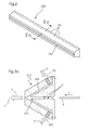
- a nozzle bar 200 is shown as shown in FIG Fig. 1 illustrated sheet punching and embossing machine 100 is used.
- the nozzle bar 200 has distributed over its working width compressed air connections 201.
- a sheet transport channel 202 In the middle of the nozzle bar 200 with trapezoidal cross-section is a sheet transport channel 202. Die How the nozzle bar works is shown in the sectional view in Fig. 2a ,
- the sheet transport channel 202 of the nozzle beam 200 is located in the sheet transport plane T.
- An arc 6 is sucked by the pressure prevailing in the vacuum region U of the sheet transport channel 202 negative pressure, pulled into the sheet transport channel 202, accelerated and transported by the blowing air b in the sheet transport direction F.
- the negative pressure in the negative pressure region U arises due to the Venturi effect.
- Compressed air a is supplied to the compressed air ports 201 of the nozzle beam 200.
- the compressed air a flows through the flow channel 204 and according to the law of Bernoulli forms a negative pressure in the negative pressure region U and the air escapes as blowing air b.
- the height of the sheet transport channel 202 can be adapted to the product thickness of the sheet 6 (not shown).
Landscapes
- Engineering & Computer Science (AREA)
- Mechanical Engineering (AREA)
- Physics & Mathematics (AREA)
- Fluid Mechanics (AREA)
- Delivering By Means Of Belts And Rollers (AREA)
- Cultivation Receptacles Or Flower-Pots, Or Pots For Seedlings (AREA)
Applications Claiming Priority (1)
| Application Number | Priority Date | Filing Date | Title |
|---|---|---|---|
| DE102007012435 | 2007-03-15 |
Publications (2)
| Publication Number | Publication Date |
|---|---|
| EP1970334A2 true EP1970334A2 (fr) | 2008-09-17 |
| EP1970334A3 EP1970334A3 (fr) | 2009-12-30 |
Family
ID=39535462
Family Applications (1)
| Application Number | Title | Priority Date | Filing Date |
|---|---|---|---|
| EP08101859A Withdrawn EP1970334A3 (fr) | 2007-03-15 | 2008-02-22 | Machine de traitement de feuilles dotée d'un dispositif de transport pneumatique |
Country Status (2)
| Country | Link |
|---|---|
| EP (1) | EP1970334A3 (fr) |
| DE (1) | DE102008010984A1 (fr) |
Cited By (3)
| Publication number | Priority date | Publication date | Assignee | Title |
|---|---|---|---|---|
| EP2093057A1 (fr) * | 2008-02-20 | 2009-08-26 | SPM Steuer GmbH & Co. KG | Procédé d'élimination d'une bande d'estampage usagée et dispositif d'estampage doté d'un dispositif d'élimination travaillant en continu |
| CN113128089A (zh) * | 2021-04-07 | 2021-07-16 | 中国辐射防护研究院 | 一种高密度屏蔽物质颗粒气力输运装置的设计方法及装置 |
| US20220315365A1 (en) * | 2021-03-30 | 2022-10-06 | Foxlink Image Technology Co., Ltd. | Pneumatic transmission device |
Families Citing this family (1)
| Publication number | Priority date | Publication date | Assignee | Title |
|---|---|---|---|---|
| DE102008061506A1 (de) * | 2008-12-10 | 2010-06-17 | Giesecke & Devrient Gmbh | Verfahren und Vorrichtung zum Führen von Wertdokumenten |
Citations (5)
| Publication number | Priority date | Publication date | Assignee | Title |
|---|---|---|---|---|
| DE3841909C2 (fr) | 1988-04-02 | 1990-09-13 | Hilmar 5653 Leichlingen De Vits | |
| DE4406848C2 (de) | 1994-03-03 | 1997-11-06 | Koenig & Bauer Albert Ag | Blaskasten zum schwebenden Führen von Bogen oder Bahnen |
| DE19515846C2 (de) | 1995-04-29 | 2000-06-08 | Heidelberger Druckmasch Ag | Schwebeelement zur Bogenführung in einer Druckmaschine oder dergleichen |
| DE202005005878U1 (de) | 2005-04-13 | 2005-06-09 | Man Roland Druckmaschinen Ag | Führungseinrichtung zur schwebenden Führung von Bahn- oder Bogenmaterial |
| DE102006017461A1 (de) | 2005-05-02 | 2006-11-09 | Heidelberger Druckmaschinen Ag | Verfahren und Vorrichtung zum Tragen eines Bedruckstoffbogens auf einem Luftpolster |
Family Cites Families (4)
| Publication number | Priority date | Publication date | Assignee | Title |
|---|---|---|---|---|
| CH690470A5 (fr) * | 1994-06-17 | 2000-09-15 | Bobst Sa | Dispositif pour assurer la qualité de la production d'une presse de fabrication d'emballages. |
| EP0960845A1 (fr) * | 1998-05-28 | 1999-12-01 | Xerox Corporation | Chemin d'alimentation de papier pneumatique |
| US6607320B2 (en) * | 2001-03-30 | 2003-08-19 | Xerox Corporation | Mobius combination of reversion and return path in a paper transport system |
| US20030131943A1 (en) * | 2002-01-17 | 2003-07-17 | Frederisy Douglas R. | Apparatus and method for assembling absorbent garments |
-
2008
- 2008-02-22 EP EP08101859A patent/EP1970334A3/fr not_active Withdrawn
- 2008-02-25 DE DE102008010984A patent/DE102008010984A1/de not_active Withdrawn
Patent Citations (5)
| Publication number | Priority date | Publication date | Assignee | Title |
|---|---|---|---|---|
| DE3841909C2 (fr) | 1988-04-02 | 1990-09-13 | Hilmar 5653 Leichlingen De Vits | |
| DE4406848C2 (de) | 1994-03-03 | 1997-11-06 | Koenig & Bauer Albert Ag | Blaskasten zum schwebenden Führen von Bogen oder Bahnen |
| DE19515846C2 (de) | 1995-04-29 | 2000-06-08 | Heidelberger Druckmasch Ag | Schwebeelement zur Bogenführung in einer Druckmaschine oder dergleichen |
| DE202005005878U1 (de) | 2005-04-13 | 2005-06-09 | Man Roland Druckmaschinen Ag | Führungseinrichtung zur schwebenden Führung von Bahn- oder Bogenmaterial |
| DE102006017461A1 (de) | 2005-05-02 | 2006-11-09 | Heidelberger Druckmaschinen Ag | Verfahren und Vorrichtung zum Tragen eines Bedruckstoffbogens auf einem Luftpolster |
Cited By (5)
| Publication number | Priority date | Publication date | Assignee | Title |
|---|---|---|---|---|
| EP2093057A1 (fr) * | 2008-02-20 | 2009-08-26 | SPM Steuer GmbH & Co. KG | Procédé d'élimination d'une bande d'estampage usagée et dispositif d'estampage doté d'un dispositif d'élimination travaillant en continu |
| US20220315365A1 (en) * | 2021-03-30 | 2022-10-06 | Foxlink Image Technology Co., Ltd. | Pneumatic transmission device |
| US11952237B2 (en) * | 2021-03-30 | 2024-04-09 | Foxlink Image Technology Co., Ltd. | Pneumatic transmission device |
| CN113128089A (zh) * | 2021-04-07 | 2021-07-16 | 中国辐射防护研究院 | 一种高密度屏蔽物质颗粒气力输运装置的设计方法及装置 |
| CN113128089B (zh) * | 2021-04-07 | 2022-10-21 | 中国辐射防护研究院 | 一种高密度屏蔽物质颗粒气力输运装置的设计方法及装置 |
Also Published As
| Publication number | Publication date |
|---|---|
| DE102008010984A1 (de) | 2008-09-18 |
| EP1970334A3 (fr) | 2009-12-30 |
Similar Documents
| Publication | Publication Date | Title |
|---|---|---|
| DE102019118647B3 (de) | Produktionslinie zur Bearbeitung von Blechtafeln | |
| DE102013010750A1 (de) | Bogenanleger und Verfahren zur Schuppenstrombildung | |
| DE102020124433B4 (de) | Anleger einer Bogen be- oder verarbeitende Maschine sowie Verfahren zur Unterstützung der Bogenvereinzelung in einem Anleger einer Bogen be- oder verarbeitende Maschine | |
| EP1935820B1 (fr) | Machine de traitement de feuilles dotée d'un dispositif de freinage de feuilles et procédé de nettoyage d'un dispositif de freinage de feuilles | |
| DE102012019051B4 (de) | Transportvorrichtung für Bogen mit obenliegender Blasluftkammer | |
| DE102008010984A1 (de) | Bogen bearbeitende Maschine mit pneumatischer Transportvorrichtung | |
| DE2137115A1 (de) | Bogenfoerdereinrichtung | |
| DE10112759A1 (de) | Verfahren und Vorrichtung zur berührungslosen Führung von Bogen | |
| DE102020122815B4 (de) | Blasvorrichtung sowie Anleger einer Bogen be- oder verarbeitende Maschine mit einer Blasvorrichtung | |
| EP1431011B1 (fr) | Presse de découpage et cannelage | |
| EP2885234A1 (fr) | Dispositif pour enlever et déposer des feuilles sur une pile | |
| DE102023110016B3 (de) | Förderanlage für einen liegenden Transport von Blechtafeln | |
| DE10033490B4 (de) | Einrichtung zum seitlichen Ausrichten von Bogen | |
| DE10323468A1 (de) | Bogen verarbeitende Maschine mit einer pneumatischen Bogenleitvorrichtung | |
| DE2457069A1 (de) | Vorrichtung zum passergerechten anlegen von bogen in bogenrotationsdruckmaschinen | |
| DE102012206848B4 (de) | Entnahmevorrichtung zur Entnahme von Flachteilen | |
| DE102021115423A1 (de) | Anleger einer Bogenbearbeitungsmaschine und Verfahren zum Bogentrennen | |
| EP1251096B1 (fr) | Plieuse à lame avec des butées réglables dépendant du format | |
| DE102016002601A1 (de) | Vorrichtung zum linearen korrigierenden Transport von Bandmedien | |
| DE102023122040B4 (de) | Anleger einer bogenverarbeitenden Maschine und Verfahren zum Betreiben eines Anlegers einer bogenverarbeitenden Maschine | |
| DE102015220406B4 (de) | Auslage und Verfahren zum Ablegen von Bogen auf einem Bogenstapel | |
| DE102023127065B4 (de) | Bearbeitungsmaschine und Verfahren zum Positionieren mindestens einer Ausbrechplatte mindestens eines Werkzeugs mindestens eines Ausbrechaggregats einer Bearbeitungsmaschine | |
| DE202012007172U1 (de) | Vorrichtung zum Banderolieren von Druckerzeugnissen und Zufuhreinheit für eine derartige Vorrichtung | |
| DE102013006348A1 (de) | Oberwerkzeug, Bearbeitungsstation und Verfahren zum Ausbrechen | |
| DE102011017560B4 (de) | Bogenbremse mit axial verstellbaren Bremsstationen |
Legal Events
| Date | Code | Title | Description |
|---|---|---|---|
| PUAI | Public reference made under article 153(3) epc to a published international application that has entered the european phase |
Free format text: ORIGINAL CODE: 0009012 |
|
| AK | Designated contracting states |
Kind code of ref document: A2 Designated state(s): AT BE BG CH CY CZ DE DK EE ES FI FR GB GR HR HU IE IS IT LI LT LU LV MC MT NL NO PL PT RO SE SI SK TR |
|
| AX | Request for extension of the european patent |
Extension state: AL BA MK RS |
|
| PUAL | Search report despatched |
Free format text: ORIGINAL CODE: 0009013 |
|
| AK | Designated contracting states |
Kind code of ref document: A3 Designated state(s): AT BE BG CH CY CZ DE DK EE ES FI FR GB GR HR HU IE IS IT LI LT LU LV MC MT NL NO PL PT RO SE SI SK TR |
|
| AX | Request for extension of the european patent |
Extension state: AL BA MK RS |
|
| 17P | Request for examination filed |
Effective date: 20100630 |
|
| AKX | Designation fees paid |
Designated state(s): AT BE BG CH CY CZ DE DK EE ES FI FR GB GR HR HU IE IS IT LI LT LU LV MC MT NL NO PL PT RO SE SI SK TR |
|
| 17Q | First examination report despatched |
Effective date: 20100910 |
|
| GRAP | Despatch of communication of intention to grant a patent |
Free format text: ORIGINAL CODE: EPIDOSNIGR1 |
|
| RIC1 | Information provided on ipc code assigned before grant |
Ipc: B65G 51/03 20060101ALI20110420BHEP Ipc: B65H 5/22 20060101AFI20110420BHEP |
|
| RTI1 | Title (correction) |
Free format text: SHEET PROCESSING MACHINE WITH PNEUMATIC TRANSPORT DEVICE |
|
| STAA | Information on the status of an ep patent application or granted ep patent |
Free format text: STATUS: THE APPLICATION IS DEEMED TO BE WITHDRAWN |
|
| 18D | Application deemed to be withdrawn |
Effective date: 20110928 |