EP1970650A2 - Vanne à trois voies - Google Patents
Vanne à trois voies Download PDFInfo
- Publication number
- EP1970650A2 EP1970650A2 EP08004516A EP08004516A EP1970650A2 EP 1970650 A2 EP1970650 A2 EP 1970650A2 EP 08004516 A EP08004516 A EP 08004516A EP 08004516 A EP08004516 A EP 08004516A EP 1970650 A2 EP1970650 A2 EP 1970650A2
- Authority
- EP
- European Patent Office
- Prior art keywords
- flow
- heat
- switching valve
- adsorber
- way switching
- Prior art date
- Legal status (The legal status is an assumption and is not a legal conclusion. Google has not performed a legal analysis and makes no representation as to the accuracy of the status listed.)
- Granted
Links
- 238000001179 sorption measurement Methods 0.000 claims description 18
- 238000003795 desorption Methods 0.000 claims description 11
- 239000012530 fluid Substances 0.000 description 15
- 239000003507 refrigerant Substances 0.000 description 11
- 230000007613 environmental effect Effects 0.000 description 6
- 238000010438 heat treatment Methods 0.000 description 5
- XLYOFNOQVPJJNP-UHFFFAOYSA-N water Substances O XLYOFNOQVPJJNP-UHFFFAOYSA-N 0.000 description 3
- 238000009833 condensation Methods 0.000 description 1
- 230000005494 condensation Effects 0.000 description 1
- 230000001419 dependent effect Effects 0.000 description 1
- 230000000694 effects Effects 0.000 description 1
- 230000017525 heat dissipation Effects 0.000 description 1
- 239000008236 heating water Substances 0.000 description 1
- 238000000034 method Methods 0.000 description 1
- 229920006395 saturated elastomer Polymers 0.000 description 1
Images


Classifications
-
- F—MECHANICAL ENGINEERING; LIGHTING; HEATING; WEAPONS; BLASTING
- F25—REFRIGERATION OR COOLING; COMBINED HEATING AND REFRIGERATION SYSTEMS; HEAT PUMP SYSTEMS; MANUFACTURE OR STORAGE OF ICE; LIQUEFACTION SOLIDIFICATION OF GASES
- F25B—REFRIGERATION MACHINES, PLANTS OR SYSTEMS; COMBINED HEATING AND REFRIGERATION SYSTEMS; HEAT PUMP SYSTEMS
- F25B17/00—Sorption machines, plants or systems, operating intermittently, e.g. absorption or adsorption type
- F25B17/08—Sorption machines, plants or systems, operating intermittently, e.g. absorption or adsorption type the absorbent or adsorbent being a solid, e.g. salt
-
- F—MECHANICAL ENGINEERING; LIGHTING; HEATING; WEAPONS; BLASTING
- F16—ENGINEERING ELEMENTS AND UNITS; GENERAL MEASURES FOR PRODUCING AND MAINTAINING EFFECTIVE FUNCTIONING OF MACHINES OR INSTALLATIONS; THERMAL INSULATION IN GENERAL
- F16K—VALVES; TAPS; COCKS; ACTUATING-FLOATS; DEVICES FOR VENTING OR AERATING
- F16K11/00—Multiple-way valves, e.g. mixing valves; Pipe fittings incorporating such valves
- F16K11/02—Multiple-way valves, e.g. mixing valves; Pipe fittings incorporating such valves with all movable sealing faces moving as one unit
- F16K11/08—Multiple-way valves, e.g. mixing valves; Pipe fittings incorporating such valves with all movable sealing faces moving as one unit comprising only taps or cocks
- F16K11/087—Multiple-way valves, e.g. mixing valves; Pipe fittings incorporating such valves with all movable sealing faces moving as one unit comprising only taps or cocks with spherical plug
- F16K11/0873—Multiple-way valves, e.g. mixing valves; Pipe fittings incorporating such valves with all movable sealing faces moving as one unit comprising only taps or cocks with spherical plug the plug being only rotatable around one spindle
-
- F—MECHANICAL ENGINEERING; LIGHTING; HEATING; WEAPONS; BLASTING
- F16—ENGINEERING ELEMENTS AND UNITS; GENERAL MEASURES FOR PRODUCING AND MAINTAINING EFFECTIVE FUNCTIONING OF MACHINES OR INSTALLATIONS; THERMAL INSULATION IN GENERAL
- F16K—VALVES; TAPS; COCKS; ACTUATING-FLOATS; DEVICES FOR VENTING OR AERATING
- F16K5/00—Plug valves; Taps or cocks comprising only cut-off apparatus having at least one of the sealing faces shaped as a more or less complete surface of a solid of revolution, the opening and closing movement being predominantly rotary
- F16K5/08—Details
- F16K5/10—Means for additional adjustment of the rate of flow
-
- F—MECHANICAL ENGINEERING; LIGHTING; HEATING; WEAPONS; BLASTING
- F25—REFRIGERATION OR COOLING; COMBINED HEATING AND REFRIGERATION SYSTEMS; HEAT PUMP SYSTEMS; MANUFACTURE OR STORAGE OF ICE; LIQUEFACTION SOLIDIFICATION OF GASES
- F25B—REFRIGERATION MACHINES, PLANTS OR SYSTEMS; COMBINED HEATING AND REFRIGERATION SYSTEMS; HEAT PUMP SYSTEMS
- F25B41/00—Fluid-circulation arrangements
- F25B41/20—Disposition of valves, e.g. of on-off valves or flow control valves
-
- F—MECHANICAL ENGINEERING; LIGHTING; HEATING; WEAPONS; BLASTING
- F25—REFRIGERATION OR COOLING; COMBINED HEATING AND REFRIGERATION SYSTEMS; HEAT PUMP SYSTEMS; MANUFACTURE OR STORAGE OF ICE; LIQUEFACTION SOLIDIFICATION OF GASES
- F25B—REFRIGERATION MACHINES, PLANTS OR SYSTEMS; COMBINED HEATING AND REFRIGERATION SYSTEMS; HEAT PUMP SYSTEMS
- F25B41/00—Fluid-circulation arrangements
- F25B41/20—Disposition of valves, e.g. of on-off valves or flow control valves
- F25B41/28—Disposition of valves, e.g. of on-off valves or flow control valves specially adapted for sorption cycles
-
- F—MECHANICAL ENGINEERING; LIGHTING; HEATING; WEAPONS; BLASTING
- F25—REFRIGERATION OR COOLING; COMBINED HEATING AND REFRIGERATION SYSTEMS; HEAT PUMP SYSTEMS; MANUFACTURE OR STORAGE OF ICE; LIQUEFACTION SOLIDIFICATION OF GASES
- F25B—REFRIGERATION MACHINES, PLANTS OR SYSTEMS; COMBINED HEATING AND REFRIGERATION SYSTEMS; HEAT PUMP SYSTEMS
- F25B41/00—Fluid-circulation arrangements
- F25B41/30—Expansion means; Dispositions thereof
-
- Y—GENERAL TAGGING OF NEW TECHNOLOGICAL DEVELOPMENTS; GENERAL TAGGING OF CROSS-SECTIONAL TECHNOLOGIES SPANNING OVER SEVERAL SECTIONS OF THE IPC; TECHNICAL SUBJECTS COVERED BY FORMER USPC CROSS-REFERENCE ART COLLECTIONS [XRACs] AND DIGESTS
- Y02—TECHNOLOGIES OR APPLICATIONS FOR MITIGATION OR ADAPTATION AGAINST CLIMATE CHANGE
- Y02A—TECHNOLOGIES FOR ADAPTATION TO CLIMATE CHANGE
- Y02A30/00—Adapting or protecting infrastructure or their operation
- Y02A30/27—Relating to heating, ventilation or air conditioning [HVAC] technologies
-
- Y—GENERAL TAGGING OF NEW TECHNOLOGICAL DEVELOPMENTS; GENERAL TAGGING OF CROSS-SECTIONAL TECHNOLOGIES SPANNING OVER SEVERAL SECTIONS OF THE IPC; TECHNICAL SUBJECTS COVERED BY FORMER USPC CROSS-REFERENCE ART COLLECTIONS [XRACs] AND DIGESTS
- Y02—TECHNOLOGIES OR APPLICATIONS FOR MITIGATION OR ADAPTATION AGAINST CLIMATE CHANGE
- Y02B—CLIMATE CHANGE MITIGATION TECHNOLOGIES RELATED TO BUILDINGS, e.g. HOUSING, HOUSE APPLIANCES OR RELATED END-USER APPLICATIONS
- Y02B30/00—Energy efficient heating, ventilation or air conditioning [HVAC]
Definitions
- the invention relates to a 3-way switching valve with three ports and an adsorption heat pump with such a valve.
- a refrigerant vaporized by an environmental heat source is adsorbed by an adsorber, causing it to heat upon adsorption. This heat is dissipated as useful heat. Afterwards, the refrigerant has to be expelled from the adsorber during desorption, which then acts as a desorber, by supplying heat. The refrigerant condenses on a condenser, which in turn releases the heat as useful heat. This useful heat during desorption is significantly lower than the useful heat during adsorption. Accordingly, it may be necessary during the desorption phase to introduce additional heat into the system in addition to the heat of condensation of the desorber-derived refrigerant.
- Object of the present invention is to provide a 3-way switching valve preferably for the operation of a Adsorptions Scripumpe, which varies depending on the switching position Has flow resistance and thus allows a needs-based distribution and shut-off.
- the 3-way switching valve connects the adsorber / desorber with the heat sink and the flow through the heat source is closed. If the adsorber / desorber and the heat sink flow through in parallel, it is particularly advantageous if the flow channel, in which the throttle is located, is connected to the heat sink. This ensures that only a comparatively small part of the fluid flow is used for direct heating.
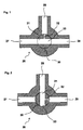
- FIG. 1 shows a 3-way switching valve 26 with three terminals 27, 28 and 29.
- a switching element 30 in the form of a ball valve with three flow channels 31, 32 and 33.
- the flow channel 32 had a smaller diameter as the two other flow channels 31 and 33, which merge seamlessly into one another while the flow channel 32 opens at right angles into the two other flow channels 31, 33.
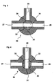
- FIGS. 1 to 4 show the 3-way switching valve 26 in each case different switching positions.
- FIG. 1 shows that the terminals 27, 29 are connected to each other via the two flow channels 31, 33.
- FIG. 2 shows the 3-way switching valve 26 with rotated by 90 ° clockwise shaft member 30.
- the terminals 28, 29 are connected to each other, while the terminal 27 is locked.
- FIG. 3 shows the 3-way switching valve 26 with again rotated by 90 ° clockwise switching element 30.
- the terminals 27, 29 are connected to each other while the terminal 28 is locked.
- the terminals 27 and 28 are connected to each other while the terminal 29 is locked.
- FIG. 5 shows a variant of the inventive 3-way switching valve 26.
- the flow channels 31, 33 have different diameters.
- the flow channel 32 has a conical course in the direction of the flow channels 31, 33, in which it opens with a throttle 34. Accordingly, the flow channel 32 in the direction of the interior of the switching element 30 has a substantially lower flow resistance than in the reverse direction.
- FIG. 6 shows an adsorption heat pump with a 3-way switching valve 26 according to the invention with a central heat pump module 12, in which an adsorber / desorber 1 and an evaporator / condenser 13 are located.
- the adsorber / desorber 1 is connected on one side to the port 27 of the 3-way switching valve 26.
- a port 28 of the 3-way switching valve 26 is connected to a heat sink 3, while the third port 29 of the 3-way switching valve 26 is connected to a heat source 2.
- the heat source 2 may take heat Q drive from, for example, a burner.
- two controllable pumps 22, 23 are arranged in series. Between these two pumps 22, 23 shows a line to Heat pump module 12 on the 3-way switching valve 26 remote side.
- the heat sink 3 is hydraulically connected to a consumer 14 via a pump 17. As a consumer 14 is a space heating and / or domestic hot water. The heat sink 3 and the consumer 14 are further connected to the heat source 2.
- the evaporator / condenser 13 is connected in parallel via in each case a check valve 24, 25 and a pump 20, 21 with an environmental heat source 15 or a consumer 16.
- FIG. 7 shows the heat pump in the operating state in which the heat pump module 12 is in the desorption phase; the adsorber / desorber 1 is therefore initially filled with refrigerant.
- the heat source 2 which may be a conventional heater, a fluid flows via the 3-way switching valve 26 to the one inlet of the adsorber / desorber 1; the output 28 of the 3-way switching valve 26 is not flowed through.
- the fluid flows through the adsorber / desorber 1 and heats it, whereby the refrigerant is expelled from the adsorber / desorber 1 and flows to the evaporator / condenser 13.
- the cooled fluid flows through the second inlet / outlet of the adsorber / desorber 1 via the controllable pump 23 back to the heat source 2. Since the output 28 of the 3-way switching valve 26 is not flowed through, the pump 22 is switched off (therefore in the figure crossed out).
- the refrigerant which was expelled from the adsorber / desorber 1 during desorption, condenses on the evaporator / condenser 13, which acts as a condenser.
- the recovered heat is conducted by means of the pump 21 to the consumer 16.
- the consumer 16 is connected via the pump 17 to the consumer 14, the useful heat Q provides benefits for service water and / or heating water.
- the pump 20 is turned off (therefore crossed out in the figure) to prevent heat dissipation to the environmental heat source 15.
- the check valve 25 prevents the pump 21 from passing warm fluid to the environmental heat source 15.
- FIG. 8 differs from FIG. 7 in that the 3-way Umschaitventil 26 is switched by 180 °, thereby enabling a bypass operation.
- the throughflow channel 32 with the smaller diameter, which opens vertically into the two other flow channels 31, 33, is now connected via the connection 28 to the heat sink 3. Due to the cross-sectional conditions and the direction of the flow channels 31, 32, 33, the largest portion of the fluid flowing into port 29 is directed towards port 27, while the remainder flows through the flow channel 32 and the port 28 to the heat sink 3.
- the partial fluid flow which flows through the heat sink 3, there outputs thermal energy in the direction of the consumer 14.
- the cooled fluid flows through the switched-controllable pump 22, combines with the fluid flow, which flows from the flow passage 31 and port 27 via the desorber 1 and is returned to the heat source 2 via the pump 23.
- Desorption with bypass according to FIG. 8 allows heat to be conducted directly from the heat source 2 to the heat sink. Since significantly less heat can be used in the desorption phase than in the adsorption phase, the available useful heat Q benefit can thereby be increased.
- FIG. 9 shows the same adsorption heat pump during the adsorption phase.
- the adsorber / desorber 1 now acts as adsorber; in the initial position it is dry.
- Environmental heat is supplied via the environmental heat source 15 to the evaporator / condenser 13, which acts as an evaporator, via the controllable pump 20.
- the evaporator 13 evaporates refrigerant in the heat pump module 12. This flows to the adsorber / desorber 1, which acts as an adsorber.
- the cooled fluid passes to the controllable pump 22 and from there to the other inlet of the adsorber / desorber 1.
- the pumps 21 and 23 are turned off in this process.
- the flow channel 32nd is in this case flowed through in the reverse direction as in FIG. 8 ,
- the flow channel 32 has a shape and throttle 34 as in FIG. 5 shown, while the flow channels 31, 33 have the same diameter and merge into each other, the 3-way Umschaltvontil 26 in the flow from port 27 to port 28 has a significantly lower flow resistance as in the flow according to FIG. 8 from port 29 to port 28.
- the 3-way switching valve 26 should throttle as little as possible, according to the desorption with bypass FIG. 8 wanted that only a relatively small part of the fluid flow to the heat sink 3 passes.
- FIG. 10 shows the heat pump in direct heating mode.
- the adsorber / desorber 1 is not flowed through, since the 3-way switching valve 26 connects the ports 29 and 28 via the flow channels 32, 31 and the output 27 seals.
- the heat that is applied to the fluid in the heat source 2 passes directly into the heat sink 3, from there via the controllable pumps 22, 23 to the starting position.
- the controllable pumps 21, 22 are switched off here.
- a plurality of adsorber / desorber 1 can be connected in parallel, wherein these can optionally be switched off individually and switched on.
- the operation of the heat pump ends in all cases with the completion of an adsorption phase.
- the adsorption phase of the adsorber / desorber 1 takes on refrigerant. After switching off thus the adsorber / desorber 1 no adsorption heat by receiving more gaseous refrigerant is more free.
- the adsorption does not necessarily have to be completely completed, but the adsorber must at least be so saturated that it does not absorb any additional refrigerant after switching off.
Landscapes
- Engineering & Computer Science (AREA)
- General Engineering & Computer Science (AREA)
- Mechanical Engineering (AREA)
- Physics & Mathematics (AREA)
- Thermal Sciences (AREA)
- Sorption Type Refrigeration Machines (AREA)
- Multiple-Way Valves (AREA)
Priority Applications (1)
| Application Number | Priority Date | Filing Date | Title |
|---|---|---|---|
| EP08004516A EP1970650B1 (fr) | 2007-03-12 | 2008-03-12 | Vanne à trois voies |
Applications Claiming Priority (2)
| Application Number | Priority Date | Filing Date | Title |
|---|---|---|---|
| AT0038407A AT504653B1 (de) | 2007-03-12 | 2007-03-12 | Adsorptions-wärmepumpe |
| EP08004516A EP1970650B1 (fr) | 2007-03-12 | 2008-03-12 | Vanne à trois voies |
Publications (3)
| Publication Number | Publication Date |
|---|---|
| EP1970650A2 true EP1970650A2 (fr) | 2008-09-17 |
| EP1970650A3 EP1970650A3 (fr) | 2009-12-23 |
| EP1970650B1 EP1970650B1 (fr) | 2012-05-30 |
Family
ID=39863090
Family Applications (1)
| Application Number | Title | Priority Date | Filing Date |
|---|---|---|---|
| EP08004516A Not-in-force EP1970650B1 (fr) | 2007-03-12 | 2008-03-12 | Vanne à trois voies |
Country Status (1)
| Country | Link |
|---|---|
| EP (1) | EP1970650B1 (fr) |
Cited By (8)
| Publication number | Priority date | Publication date | Assignee | Title |
|---|---|---|---|---|
| WO2010078957A3 (fr) * | 2008-12-19 | 2010-12-23 | Invensor Gmbh | Élément limiteur de pression permettant de diviser le débit volumique de condensation dans des machines à sorption |
| DE102015206271A1 (de) * | 2015-04-08 | 2016-10-13 | Mahle International Gmbh | Adsorptionswärmepumpe |
| US20180050187A1 (en) * | 2015-03-26 | 2018-02-22 | B. Braun Melsungen Ag | Medical fluid control device for a medical fluid line system |
| DE102017101208A1 (de) | 2017-01-23 | 2018-07-26 | Hanon Systems | Ventil für ein Wärmepumpensystem in einem Fahrzeug |
| US20190226591A1 (en) * | 2018-01-19 | 2019-07-25 | Siemens Schweiz | Valve Having A Bypass Conduit |
| CN113294545A (zh) * | 2021-05-20 | 2021-08-24 | 中车青岛四方机车车辆股份有限公司 | 管接塞门、管接塞门的组装方法及轨道车辆 |
| CN113606360A (zh) * | 2021-07-15 | 2021-11-05 | 东风富士汤姆森调温器有限公司 | 一种全通节流电子膨胀阀 |
| CN119488056A (zh) * | 2025-01-17 | 2025-02-21 | 山东省水利科学研究院 | 一种河道护坡修复装置 |
Family Cites Families (4)
| Publication number | Priority date | Publication date | Assignee | Title |
|---|---|---|---|---|
| BE1000556A7 (nl) * | 1987-05-14 | 1989-01-31 | Verschueren Josephus | Doseerafsluiter. |
| JPH0391660A (ja) * | 1989-09-04 | 1991-04-17 | Nishiyodo Kuuchiyouki Kk | 吸着式蓄熱装置及び該装置を利用した吸着式蓄熱システム |
| US5944055A (en) * | 1997-09-05 | 1999-08-31 | Dicky; Julius | Control valve with swivel connector |
| DE10134699C2 (de) * | 2001-07-07 | 2003-10-16 | Vaillant Gmbh | Verfahren zum Betrieb einer Adsorptionswärmepumpe mit verschaltbaren Komponenten |
-
2008
- 2008-03-12 EP EP08004516A patent/EP1970650B1/fr not_active Not-in-force
Cited By (12)
| Publication number | Priority date | Publication date | Assignee | Title |
|---|---|---|---|---|
| WO2010078957A3 (fr) * | 2008-12-19 | 2010-12-23 | Invensor Gmbh | Élément limiteur de pression permettant de diviser le débit volumique de condensation dans des machines à sorption |
| US20180050187A1 (en) * | 2015-03-26 | 2018-02-22 | B. Braun Melsungen Ag | Medical fluid control device for a medical fluid line system |
| US10471248B2 (en) * | 2015-03-26 | 2019-11-12 | B. Braun Melsungen Ag | Medical fluid control device for a medical fluid line system |
| DE102015206271A1 (de) * | 2015-04-08 | 2016-10-13 | Mahle International Gmbh | Adsorptionswärmepumpe |
| US10323864B2 (en) | 2015-04-08 | 2019-06-18 | Mahle International Gmbh | Adsorption heat pump |
| DE102017101208A1 (de) | 2017-01-23 | 2018-07-26 | Hanon Systems | Ventil für ein Wärmepumpensystem in einem Fahrzeug |
| CN108344212A (zh) * | 2017-01-23 | 2018-07-31 | 翰昂汽车零部件有限公司 | 用于交通工具中的热泵系统的阀 |
| US20190226591A1 (en) * | 2018-01-19 | 2019-07-25 | Siemens Schweiz | Valve Having A Bypass Conduit |
| US10746321B2 (en) * | 2018-01-19 | 2020-08-18 | Siemens Schweiz Ag | Valve having a bypass conduit |
| CN113294545A (zh) * | 2021-05-20 | 2021-08-24 | 中车青岛四方机车车辆股份有限公司 | 管接塞门、管接塞门的组装方法及轨道车辆 |
| CN113606360A (zh) * | 2021-07-15 | 2021-11-05 | 东风富士汤姆森调温器有限公司 | 一种全通节流电子膨胀阀 |
| CN119488056A (zh) * | 2025-01-17 | 2025-02-21 | 山东省水利科学研究院 | 一种河道护坡修复装置 |
Also Published As
| Publication number | Publication date |
|---|---|
| EP1970650A3 (fr) | 2009-12-23 |
| EP1970650B1 (fr) | 2012-05-30 |
Similar Documents
| Publication | Publication Date | Title |
|---|---|---|
| EP1970650B1 (fr) | Vanne à trois voies | |
| DE69735216T2 (de) | Adsorptionskältegerät | |
| AT504653B1 (de) | Adsorptions-wärmepumpe | |
| EP2304341B1 (fr) | Procédé de transmission thermique entre des adsorbeurs travaillant en alternance et dispositif correspondant | |
| EP4416435A1 (fr) | Appareil pour chauffer et/ou refroidir un fluide, et système de climatisation | |
| EP3136005A1 (fr) | Installation de chauffage et son procede de fonctionnement | |
| DE2453899A1 (de) | Waermeaustauscher, insbesondere fuer waermepumpen mit verdichter | |
| DE102015114474A1 (de) | Wärmepumpenanlage und Verfahren zum Betrieb einer Wärmepumpenanlage | |
| EP1985948B1 (fr) | Dispositif de sorption sous vide et procédé de fonctionnement d'un dispositif de sorption sous vide | |
| DE102011003664A1 (de) | Wärmepumpe | |
| DE102006011409A1 (de) | Adsorptionsmaschine mit Wärmerückgewinnung | |
| DE102016000317A1 (de) | Mehrwegeventil für ein Heiz-und Kühlsystem eines Fahrzeugs | |
| DE102018201942A1 (de) | Mehrwegeregelventil | |
| DE10158104B4 (de) | Wärmemanagementvorrichtung für ein Kraftfahrzeug | |
| DE102013021285A1 (de) | Haustechnikgerät und Wärmespeichereinheit | |
| CH690197A5 (de) | Adsorptionswärmepumpe. | |
| DE102022132793A1 (de) | Verfahren zum Betrieb einer Heizungsanlage und Heizungsanlage | |
| DE102004049409B3 (de) | Vakuum-Sorptionsvorrichtung | |
| EP2345854B1 (fr) | Echangeur thermique à sorption et commande associée | |
| DE102009057159A1 (de) | Sorptionswärmetauscher und Steuerung hierfür | |
| DE102012208175A1 (de) | Wärmepumpensystem und verfahren zum pumpen von wärme | |
| AT410369B (de) | Adsorptionswärmepumpe | |
| EP1845313A1 (fr) | Appareil à accumulation de chaleur | |
| EP3186568A1 (fr) | Dispositif d'adsorption, dispositif de chauffage, véhicule automobile | |
| DE102014211703A1 (de) | Rotationsventil für eine Adsorptionswärmepumpe |
Legal Events
| Date | Code | Title | Description |
|---|---|---|---|
| PUAI | Public reference made under article 153(3) epc to a published international application that has entered the european phase |
Free format text: ORIGINAL CODE: 0009012 |
|
| AK | Designated contracting states |
Kind code of ref document: A2 Designated state(s): AT BE BG CH CY CZ DE DK EE ES FI FR GB GR HR HU IE IS IT LI LT LU LV MC MT NL NO PL PT RO SE SI SK TR |
|
| AX | Request for extension of the european patent |
Extension state: AL BA MK RS |
|
| PUAL | Search report despatched |
Free format text: ORIGINAL CODE: 0009013 |
|
| AK | Designated contracting states |
Kind code of ref document: A3 Designated state(s): AT BE BG CH CY CZ DE DK EE ES FI FR GB GR HR HU IE IS IT LI LT LU LV MC MT NL NO PL PT RO SE SI SK TR |
|
| AX | Request for extension of the european patent |
Extension state: AL BA MK RS |
|
| 17P | Request for examination filed |
Effective date: 20100426 |
|
| 17Q | First examination report despatched |
Effective date: 20100609 |
|
| AKX | Designation fees paid |
Designated state(s): AT BE BG CH CY CZ DE DK EE ES FI FR GB GR HR HU IE IS IT LI LT LU LV MC MT NL NO PL PT RO SE SI SK TR |
|
| REG | Reference to a national code |
Ref country code: DE Ref legal event code: R079 Ref document number: 502008007281 Country of ref document: DE Free format text: PREVIOUS MAIN CLASS: F25B0041040000 Ipc: F25B0017080000 |
|
| GRAP | Despatch of communication of intention to grant a patent |
Free format text: ORIGINAL CODE: EPIDOSNIGR1 |
|
| RIC1 | Information provided on ipc code assigned before grant |
Ipc: F25B 41/06 20060101ALI20111124BHEP Ipc: F16K 11/087 20060101ALI20111124BHEP Ipc: F16K 5/10 20060101ALI20111124BHEP Ipc: F25B 17/08 20060101AFI20111124BHEP Ipc: F25B 41/04 20060101ALI20111124BHEP |
|
| GRAS | Grant fee paid |
Free format text: ORIGINAL CODE: EPIDOSNIGR3 |
|
| GRAA | (expected) grant |
Free format text: ORIGINAL CODE: 0009210 |
|
| AK | Designated contracting states |
Kind code of ref document: B1 Designated state(s): AT BE BG CH CY CZ DE DK EE ES FI FR GB GR HR HU IE IS IT LI LT LU LV MC MT NL NO PL PT RO SE SI SK TR |
|
| REG | Reference to a national code |
Ref country code: GB Ref legal event code: FG4D Free format text: NOT ENGLISH |
|
| REG | Reference to a national code |
Ref country code: CH Ref legal event code: EP |
|
| REG | Reference to a national code |
Ref country code: AT Ref legal event code: REF Ref document number: 560252 Country of ref document: AT Kind code of ref document: T Effective date: 20120615 |
|
| REG | Reference to a national code |
Ref country code: IE Ref legal event code: FG4D Free format text: LANGUAGE OF EP DOCUMENT: GERMAN |
|
| REG | Reference to a national code |
Ref country code: DE Ref legal event code: R096 Ref document number: 502008007281 Country of ref document: DE Effective date: 20120726 |
|
| REG | Reference to a national code |
Ref country code: NL Ref legal event code: VDEP Effective date: 20120530 |
|
| REG | Reference to a national code |
Ref country code: LT Ref legal event code: MG4D Effective date: 20120530 |
|
| PG25 | Lapsed in a contracting state [announced via postgrant information from national office to epo] |
Ref country code: LT Free format text: LAPSE BECAUSE OF FAILURE TO SUBMIT A TRANSLATION OF THE DESCRIPTION OR TO PAY THE FEE WITHIN THE PRESCRIBED TIME-LIMIT Effective date: 20120530 Ref country code: SE Free format text: LAPSE BECAUSE OF FAILURE TO SUBMIT A TRANSLATION OF THE DESCRIPTION OR TO PAY THE FEE WITHIN THE PRESCRIBED TIME-LIMIT Effective date: 20120530 Ref country code: IS Free format text: LAPSE BECAUSE OF FAILURE TO SUBMIT A TRANSLATION OF THE DESCRIPTION OR TO PAY THE FEE WITHIN THE PRESCRIBED TIME-LIMIT Effective date: 20120930 Ref country code: NO Free format text: LAPSE BECAUSE OF FAILURE TO SUBMIT A TRANSLATION OF THE DESCRIPTION OR TO PAY THE FEE WITHIN THE PRESCRIBED TIME-LIMIT Effective date: 20120830 Ref country code: CY Free format text: LAPSE BECAUSE OF FAILURE TO SUBMIT A TRANSLATION OF THE DESCRIPTION OR TO PAY THE FEE WITHIN THE PRESCRIBED TIME-LIMIT Effective date: 20120530 Ref country code: FI Free format text: LAPSE BECAUSE OF FAILURE TO SUBMIT A TRANSLATION OF THE DESCRIPTION OR TO PAY THE FEE WITHIN THE PRESCRIBED TIME-LIMIT Effective date: 20120530 |
|
| PG25 | Lapsed in a contracting state [announced via postgrant information from national office to epo] |
Ref country code: HR Free format text: LAPSE BECAUSE OF FAILURE TO SUBMIT A TRANSLATION OF THE DESCRIPTION OR TO PAY THE FEE WITHIN THE PRESCRIBED TIME-LIMIT Effective date: 20120530 Ref country code: GR Free format text: LAPSE BECAUSE OF FAILURE TO SUBMIT A TRANSLATION OF THE DESCRIPTION OR TO PAY THE FEE WITHIN THE PRESCRIBED TIME-LIMIT Effective date: 20120831 Ref country code: LV Free format text: LAPSE BECAUSE OF FAILURE TO SUBMIT A TRANSLATION OF THE DESCRIPTION OR TO PAY THE FEE WITHIN THE PRESCRIBED TIME-LIMIT Effective date: 20120530 Ref country code: SI Free format text: LAPSE BECAUSE OF FAILURE TO SUBMIT A TRANSLATION OF THE DESCRIPTION OR TO PAY THE FEE WITHIN THE PRESCRIBED TIME-LIMIT Effective date: 20120530 |
|
| PG25 | Lapsed in a contracting state [announced via postgrant information from national office to epo] |
Ref country code: NL Free format text: LAPSE BECAUSE OF FAILURE TO SUBMIT A TRANSLATION OF THE DESCRIPTION OR TO PAY THE FEE WITHIN THE PRESCRIBED TIME-LIMIT Effective date: 20120530 Ref country code: EE Free format text: LAPSE BECAUSE OF FAILURE TO SUBMIT A TRANSLATION OF THE DESCRIPTION OR TO PAY THE FEE WITHIN THE PRESCRIBED TIME-LIMIT Effective date: 20120530 Ref country code: DK Free format text: LAPSE BECAUSE OF FAILURE TO SUBMIT A TRANSLATION OF THE DESCRIPTION OR TO PAY THE FEE WITHIN THE PRESCRIBED TIME-LIMIT Effective date: 20120530 Ref country code: CZ Free format text: LAPSE BECAUSE OF FAILURE TO SUBMIT A TRANSLATION OF THE DESCRIPTION OR TO PAY THE FEE WITHIN THE PRESCRIBED TIME-LIMIT Effective date: 20120530 Ref country code: RO Free format text: LAPSE BECAUSE OF FAILURE TO SUBMIT A TRANSLATION OF THE DESCRIPTION OR TO PAY THE FEE WITHIN THE PRESCRIBED TIME-LIMIT Effective date: 20120530 Ref country code: SK Free format text: LAPSE BECAUSE OF FAILURE TO SUBMIT A TRANSLATION OF THE DESCRIPTION OR TO PAY THE FEE WITHIN THE PRESCRIBED TIME-LIMIT Effective date: 20120530 |
|
| PG25 | Lapsed in a contracting state [announced via postgrant information from national office to epo] |
Ref country code: PL Free format text: LAPSE BECAUSE OF FAILURE TO SUBMIT A TRANSLATION OF THE DESCRIPTION OR TO PAY THE FEE WITHIN THE PRESCRIBED TIME-LIMIT Effective date: 20120530 Ref country code: PT Free format text: LAPSE BECAUSE OF FAILURE TO SUBMIT A TRANSLATION OF THE DESCRIPTION OR TO PAY THE FEE WITHIN THE PRESCRIBED TIME-LIMIT Effective date: 20121001 Ref country code: IT Free format text: LAPSE BECAUSE OF FAILURE TO SUBMIT A TRANSLATION OF THE DESCRIPTION OR TO PAY THE FEE WITHIN THE PRESCRIBED TIME-LIMIT Effective date: 20120530 |
|
| PLBE | No opposition filed within time limit |
Free format text: ORIGINAL CODE: 0009261 |
|
| STAA | Information on the status of an ep patent application or granted ep patent |
Free format text: STATUS: NO OPPOSITION FILED WITHIN TIME LIMIT |
|
| PG25 | Lapsed in a contracting state [announced via postgrant information from national office to epo] |
Ref country code: ES Free format text: LAPSE BECAUSE OF FAILURE TO SUBMIT A TRANSLATION OF THE DESCRIPTION OR TO PAY THE FEE WITHIN THE PRESCRIBED TIME-LIMIT Effective date: 20120910 |
|
| 26N | No opposition filed |
Effective date: 20130301 |
|
| REG | Reference to a national code |
Ref country code: DE Ref legal event code: R097 Ref document number: 502008007281 Country of ref document: DE Effective date: 20130301 |
|
| PG25 | Lapsed in a contracting state [announced via postgrant information from national office to epo] |
Ref country code: BG Free format text: LAPSE BECAUSE OF FAILURE TO SUBMIT A TRANSLATION OF THE DESCRIPTION OR TO PAY THE FEE WITHIN THE PRESCRIBED TIME-LIMIT Effective date: 20120830 |
|
| BERE | Be: lapsed |
Owner name: VAILLANT G.M.B.H. Effective date: 20130331 |
|
| PG25 | Lapsed in a contracting state [announced via postgrant information from national office to epo] |
Ref country code: MC Free format text: LAPSE BECAUSE OF NON-PAYMENT OF DUE FEES Effective date: 20130331 |
|
| GBPC | Gb: european patent ceased through non-payment of renewal fee |
Effective date: 20130312 |
|
| REG | Reference to a national code |
Ref country code: FR Ref legal event code: ST Effective date: 20131129 |
|
| REG | Reference to a national code |
Ref country code: IE Ref legal event code: MM4A |
|
| PG25 | Lapsed in a contracting state [announced via postgrant information from national office to epo] |
Ref country code: FR Free format text: LAPSE BECAUSE OF NON-PAYMENT OF DUE FEES Effective date: 20130402 Ref country code: BE Free format text: LAPSE BECAUSE OF NON-PAYMENT OF DUE FEES Effective date: 20130331 Ref country code: GB Free format text: LAPSE BECAUSE OF NON-PAYMENT OF DUE FEES Effective date: 20130312 Ref country code: IE Free format text: LAPSE BECAUSE OF NON-PAYMENT OF DUE FEES Effective date: 20130312 |
|
| PG25 | Lapsed in a contracting state [announced via postgrant information from national office to epo] |
Ref country code: MT Free format text: LAPSE BECAUSE OF FAILURE TO SUBMIT A TRANSLATION OF THE DESCRIPTION OR TO PAY THE FEE WITHIN THE PRESCRIBED TIME-LIMIT Effective date: 20120530 |
|
| PG25 | Lapsed in a contracting state [announced via postgrant information from national office to epo] |
Ref country code: TR Free format text: LAPSE BECAUSE OF FAILURE TO SUBMIT A TRANSLATION OF THE DESCRIPTION OR TO PAY THE FEE WITHIN THE PRESCRIBED TIME-LIMIT Effective date: 20120530 |
|
| PG25 | Lapsed in a contracting state [announced via postgrant information from national office to epo] |
Ref country code: LU Free format text: LAPSE BECAUSE OF NON-PAYMENT OF DUE FEES Effective date: 20130312 Ref country code: HU Free format text: LAPSE BECAUSE OF FAILURE TO SUBMIT A TRANSLATION OF THE DESCRIPTION OR TO PAY THE FEE WITHIN THE PRESCRIBED TIME-LIMIT; INVALID AB INITIO Effective date: 20080312 |
|
| PGFP | Annual fee paid to national office [announced via postgrant information from national office to epo] |
Ref country code: AT Payment date: 20210301 Year of fee payment: 14 |
|
| PGFP | Annual fee paid to national office [announced via postgrant information from national office to epo] |
Ref country code: CH Payment date: 20220228 Year of fee payment: 15 |
|
| REG | Reference to a national code |
Ref country code: AT Ref legal event code: MM01 Ref document number: 560252 Country of ref document: AT Kind code of ref document: T Effective date: 20220312 |
|
| PG25 | Lapsed in a contracting state [announced via postgrant information from national office to epo] |
Ref country code: AT Free format text: LAPSE BECAUSE OF NON-PAYMENT OF DUE FEES Effective date: 20220312 |
|
| PGFP | Annual fee paid to national office [announced via postgrant information from national office to epo] |
Ref country code: DE Payment date: 20230228 Year of fee payment: 16 |
|
| P01 | Opt-out of the competence of the unified patent court (upc) registered |
Effective date: 20230528 |
|
| REG | Reference to a national code |
Ref country code: CH Ref legal event code: PL |
|
| PG25 | Lapsed in a contracting state [announced via postgrant information from national office to epo] |
Ref country code: LI Free format text: LAPSE BECAUSE OF NON-PAYMENT OF DUE FEES Effective date: 20230331 Ref country code: CH Free format text: LAPSE BECAUSE OF NON-PAYMENT OF DUE FEES Effective date: 20230331 |
|
| REG | Reference to a national code |
Ref country code: DE Ref legal event code: R119 Ref document number: 502008007281 Country of ref document: DE |
|
| PG25 | Lapsed in a contracting state [announced via postgrant information from national office to epo] |
Ref country code: DE Free format text: LAPSE BECAUSE OF NON-PAYMENT OF DUE FEES Effective date: 20241001 |
|
| PG25 | Lapsed in a contracting state [announced via postgrant information from national office to epo] |
Ref country code: DE Free format text: LAPSE BECAUSE OF NON-PAYMENT OF DUE FEES Effective date: 20241001 |