EP1970676A1 - Détecteur thermique de débit massique avec admission inclinée dans un canal de derivation - Google Patents
Détecteur thermique de débit massique avec admission inclinée dans un canal de derivation Download PDFInfo
- Publication number
- EP1970676A1 EP1970676A1 EP08159589A EP08159589A EP1970676A1 EP 1970676 A1 EP1970676 A1 EP 1970676A1 EP 08159589 A EP08159589 A EP 08159589A EP 08159589 A EP08159589 A EP 08159589A EP 1970676 A1 EP1970676 A1 EP 1970676A1
- Authority
- EP
- European Patent Office
- Prior art keywords
- passage
- gas
- bypass passage
- flow measuring
- bypass
- Prior art date
- Legal status (The legal status is an assumption and is not a legal conclusion. Google has not performed a legal analysis and makes no representation as to the accuracy of the status listed.)
- Withdrawn
Links
Images


Classifications
-
- G—PHYSICS
- G01—MEASURING; TESTING
- G01F—MEASURING VOLUME, VOLUME FLOW, MASS FLOW OR LIQUID LEVEL; METERING BY VOLUME
- G01F5/00—Measuring a proportion of the volume flow
-
- G—PHYSICS
- G01—MEASURING; TESTING
- G01F—MEASURING VOLUME, VOLUME FLOW, MASS FLOW OR LIQUID LEVEL; METERING BY VOLUME
- G01F1/00—Measuring the volume flow or mass flow of fluid or fluent solid material wherein the fluid passes through a meter in a continuous flow
- G01F1/68—Measuring the volume flow or mass flow of fluid or fluent solid material wherein the fluid passes through a meter in a continuous flow by using thermal effects
- G01F1/684—Structural arrangements; Mounting of elements, e.g. in relation to fluid flow
- G01F1/6842—Structural arrangements; Mounting of elements, e.g. in relation to fluid flow with means for influencing the fluid flow
-
- G—PHYSICS
- G01—MEASURING; TESTING
- G01F—MEASURING VOLUME, VOLUME FLOW, MASS FLOW OR LIQUID LEVEL; METERING BY VOLUME
- G01F15/00—Details of, or accessories for, apparatus of groups G01F1/00 - G01F13/00 insofar as such details or appliances are not adapted to particular types of such apparatus
- G01F15/12—Cleaning arrangements; Filters
Definitions
- the present invention relates to gas-flow measuring instruments for measuring a gas flow of intake gas, and in particular relates to a gas-flow measuring instrument for mainly measuring a gas flow in an intake gas passage for sucking gas.
- a gas-flow measuring instrument may be mainly arranged within an intake gas passage for sucking gas, and in particular arranged within an intake gas passage of an internal combustion engine for automobiles.
- fluid represented by water may possibly intrude so as to enter the portion of the intake gas passage where the flow measuring instrument is installed. If fluid splashes contained in intake gas are stuck to the flow measuring element, an output variation of the flow measuring element is produced by a momentary change in radiant heat of the flow measuring element, so that deterioration per hour due to a rapid variation in temperature may occur or heat stress may cause damage to the flow measuring element.
- the gas-flow measuring instrument can comprise an intake gas passage and a flow measuring element, wherein there can be provided a bypass passage for guiding part of the gas flowing through the intake gas passage.
- the flow measuring element may be arranged in the bypass passage.
- the gas-flow measuring instrument comprising the intake gas passage and the flow measuring element for measuring a gas flow may further comprises detouring means for detouring water splashes arranged in a flow path where the flow measuring element exists.
- the present invention incorporates configurations of a bypass passage capable of isolating water splashes contained in gas, which, cause damage such as deterioration per hour, output variations, and breakage to a flow measuring element utilising inertial forces of the splashes, the configurations of the bypass passage being also capable of holding a sufficient gaseous body flow in a portion where the flow measuring element is arranged.
- Fig. 1 is a longitudinal sectional view of a gas-flow measuring instrument according to an embodiment of the present invention.
- a module housing 6 of the gas-flow measuring instrument is attached with a module flange 10 therebetween.
- a bypass passage 4 is provided, and within the bypass passage 4, a heating resistor 1, a temperature sensing resistor 2, and a temperature sensor 3 are arranged.
- the heating resistor 1 and the temperature sensing resistor 2 are connected to an electronic circuit 5 arranged in the module housing 6, which in turn is electrically connected outside via connector 9.
- the bypass passage 4 is constituted of a first passage 41 arranged from the upstream-side of the intake gas passage 8 to the downstream side, a second passage 42 arranged from the downstream-side to the upstream side, a third passage 43 communicating the first passage 41 with the vicinity of the end of the second passage in the downstream-side of the intake gas passage 8, and a bypass passage outlet 12 opened substantially in parallel with a mainstream direction 14 of intake gas arranged in the vicinity of the downstream end of the second passage 42 (the upstream side of the intake gas passage 8), so as to form a detouring configuration.
- the first passage 41 is inclined to the axis of the intake gas passage 8, and the heating resistor 1, the temperature sensing resistor 2, and the temperature sensor 3 are arranged in the second passage 42.
- the mainstream direction 14 is equal to the direction indicated by a dash-dotted line and the axial direction of the first passage 41 is indicated by a broken line C-C.
- fluid proceeding inside the bypass passage 4 goes straight by its own velocity and the inertial force due to its mass so as to abut on a wail of the first passage 41, which is inclined relative to the axial direction of the intake gas passage 8, so as to be stuck on the wall.
- the fluid stuck on the wall proceeds directly along an outside contour wall 44 of the bypass passage 4 in the detouring direction without splashing again into intake gas so as to be exhausted to the intake gas passage 8 again from the bypass passage outlet 12 without contacting the heating resistor 1 arranged in the vicinity of the rear of the bypass passage 4.
- the inertial force of gas itself is extremely smaller than that of the water splash, the gas flows along the detouring route of the bypass passage 4, so that a sufficient velocity necessary for stable measurement can also be obtained in the vicinity of the flow measuring element.
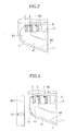
- Fig. 2 is a longitudinal sectional view of the bypass passage 4 of the gas-flow measuring instrument according to the embodiment of the present invention, and it is an example of a detouring configuration of the bypass passage. Junctional regions between the third passage 43 and the first passage 41 and between the third passage 43 and the second passage 42 are formed to have continuous curves of the outside contour wall 44 along the detouring direction of the bypass passage 4.
- Fig. 3 includes a longitudinal sectional view of a bypass passage 4 of a gas-flow measuring instrument according to another embodiment of the present invention. Different from the embodiment in Fig. 1 , it has a feature that a vent 15 is provided in the vicinity of the junctional region between the third passage 43 and the first passage 41 inside the bypass passage 4 so as to communicate the bypass passage 4 with the intake gas passage 8.
- the right side is the longitudinal sectional view of the bypass passage 4 of the gas-flow measuring instrument and the left side is a side view thereof viewed from the downstream side of the intake gas passage 8. According to this configuration, the fluid stuck on the bypass passage outside contour wall 44 of the first passage 41 can be effectively discharged outside the bypass passage 4 before it reaches the heating resistor 1.
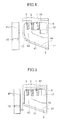
- Fig. 4 is a longitudinal sectional view of another embodiment, in which the position of the bypass passage outlet 12 is different from that of the bypass passage outlet shown in Figs. 1 and 3 . Other arrangement thereof is equal to that of Fig. 3 .
- the bypass passage outlet 12 of the type is opened substantially in parallel with an intake gas flow flowing inside the intake gas passage 8 so as to detour at about 90° in a direction of a bypass passage inlet 11 on the upstream side of the intake gas passage 8 to have the bypass passage outlet 12 opened on the bypass passage both-side walls 45.
- the length of the bypass passage 4 can be increased without changing the bypass passage inlet 11 and the bypass passage outlet 12 along the axial line of the intake gas passage 8 so as to be able to reduce the output detection error produced upon occurrence of a pulsation flow even within about the same shape and size.
- Fig. 5 is a longitudinal sectional view of another embodiment, in which the junctional region between the third passage 43 and the first passage 41 is linearly connected in comparison with the embodiment shown in Fig. 3 .
- Other arrangement thereof is equal to that of Fig. 3 .
- the vent 15 is provided on the front to which the bypass passage outside contour wall 44 proceeds directly from the upstream side of the intake gas passage 8 to the downstream side so as to communicate the bypass passage 4 with the intake gas passage 8.
- the fluid stuck on the bypass passage outside contour wall 44 proceeds directly along the bypass passage outside contour wall 44.
- the vent 15 formed at a position to which the fluid proceeds directly the fluid can be effectively discharged outside the bypass passage 4 before it reaches the heating resistor 1.
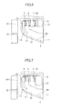
- Fig. 6 is a longitudinal sectional view of another embodiment, in which a partition 13 is provided in the vicinity of the junctional region between the third passage 43 and the first passage 41 so as to separate the bypass passage 4 in the detouring direction into external and internal peripheral directions in comparison with the embodiment shown in Fig.13.
- Other arrangement thereof is equal to that of Fig. 3 .
- fluid proceeding inside the bypass passage 4 goes straight by the inertial force due to its own weight and velocity so as to abut on the bypass passage outside contour wall 44 of the third passage 43.
- the partition 13 the fluid stuck on the bypass passage outside contour wall 44 in the inclined part of the passage is prevented from splashing again caused by a swirl flow, etc., produced in the detouring part of the bypass passage 4. Therefore, the fluid stuck on the bypass passage outside contour wall 44 proceeds more effectively along the bypass passage outside contour wall 44 of the bypass passage 4.
- Fig. 7 is a longitudinal sectional view of another embodiment, in which the structure of the bypass passage outlet 12 is equalized to that of Fig. 4 in comparison with the embodiment shown in Fig. 6 .
- Fig. 8 is a cross-sectional view at the line A..A of Fig. 1 , which is perpendicular to the axial direction of the bypass passage 4, showing another embodiment of the cross-section of the bypass passage 4.
- Fig. 9 is a cross-sectional view at the line A-A of Fig. 1 , which is perpendicular to the axial direction of the bypass passage 4, showing another embodiment of the cross-section of the bypass passage 4.
- Beveling inclined surfaces are provided in the junctional regions between the bypass passage outside contour wall 44 located in the external peripheral side of the bypass passage 4 in the detouring direction and the bypass passage both-side walls 45 forming the bypass passage 4 and arranged substantially in parallel with the axial direction of the intake gas passage 8. According to this structure, the fluid entering the bypass passage 4 and stuck to the bypass passage outside contour wall 44 in the detouring direction of the fluid bypass passage, i.e., to a ditch 17, can be effectively accumulated.
- the reflection of a water splash when the water splash abuts the bypass passage outside contour wall can be directed more close to the bypass passage outside contour surface, thereby more increasing the separation effect of the water splash, It is preferably effective that the range of the inclination be 60° to 120°.
- Fig. 10 is a cross-sectional view at the line A-A of Fig. 1 , showing another embodiment of the cross-section of the bypass passage 4.
- the bypass passage both-side walls 45 located in the outside contour surface in the detouring direction of the bypass passage 4 are U-shaped. According to this structure, the fluid entering the bypass passage 4 is accumulated to an extreme external part 18 of the bypass passage outside contour wall 44.
- Fig. 11 is a cross-sectional view at the line A-A of Fig. 1 , showing another embodiment of the cross-section of the bypass passage 4.
- the ditches 17 are provided in the junctional regions between the bypass passage outside contour wall 44 and the bypass passage both-side walls 45, and sidewalls of the ditches 17 adjacent to the center of the bypass passage 4 are inclined relative to the bypass passage both-side walls 45.
- the range of the inclination is 30° to 60°. According to this structure, the fluid entering the bypass passage 4 is accumulated into the two ditches 17 of the bypass passage outside contour wall 44.
- Fig. 12 is a cross-sectional view at the line B-B of Fig. 1 , showing another embodiment of the cross-section of the bypass passage 4.
- a venturi 16 is provided in the vicinity of the heating resistor 1 arranged in the bypass passage 4.
- the area of the second passage 42 is contracted in the vicinity of the heating resistor 1. The flow velocity of intake gas entering the bypass passage 4 is thereby increased. Even if a slow intake gas flow is sucked, the turbulence of the intake flow is stabilized, enabling output noise to be reduced.
- the fluid contained in intake gas has been described as above; dust contained in intake gas is also to proceed directly by its own inertial force similarly to fluid droplets. Therefore, the dust is accumulated on the outside contour surface of the bypass passage so as to be exhausted outside the bypass passage without abutting the flow measuring element arranged substantially at the center of the bypass passage, Accordingly, output variations per hour produced by changes in the heat capacity of the flow measuring element caused by the dust sticking to the flow measuring element can be effectively prevented, and mechanical damage of the flow measuring element itself produced by the dust, etc., abutting the flow measuring can also be prevented. Moreover, the dust, etc., entering the bypass passage abuts the bypass passage wall at one time or several times.
- Kinetic energy of the dust is consumed by the abutment, so that when the dust arrives at the flow measuring element, the kinetic energy thereof has been reduced, enabling damage subjected by the flow measuring element to be reduced even if the dust abuts the flow measuring element.
- the invention since the invention has a feature of only the configuration of the bypass passage, the advantages cannot be reduced over a period of time and consecutive advantages can be obtained.
Landscapes
- Physics & Mathematics (AREA)
- Fluid Mechanics (AREA)
- General Physics & Mathematics (AREA)
- Measuring Volume Flow (AREA)
Applications Claiming Priority (2)
| Application Number | Priority Date | Filing Date | Title |
|---|---|---|---|
| JP2002191580A JP3709385B2 (ja) | 2002-07-01 | 2002-07-01 | 内燃機関用気体流量測定装置 |
| EP03014450A EP1378729A1 (fr) | 2002-07-01 | 2003-07-01 | Détecteur thermique de débit massique avec admission inclinée dans un canal de derivation |
Related Parent Applications (1)
| Application Number | Title | Priority Date | Filing Date |
|---|---|---|---|
| EP03014450A Division EP1378729A1 (fr) | 2002-07-01 | 2003-07-01 | Détecteur thermique de débit massique avec admission inclinée dans un canal de derivation |
Publications (1)
| Publication Number | Publication Date |
|---|---|
| EP1970676A1 true EP1970676A1 (fr) | 2008-09-17 |
Family
ID=29720219
Family Applications (2)
| Application Number | Title | Priority Date | Filing Date |
|---|---|---|---|
| EP08159589A Withdrawn EP1970676A1 (fr) | 2002-07-01 | 2003-07-01 | Détecteur thermique de débit massique avec admission inclinée dans un canal de derivation |
| EP03014450A Ceased EP1378729A1 (fr) | 2002-07-01 | 2003-07-01 | Détecteur thermique de débit massique avec admission inclinée dans un canal de derivation |
Family Applications After (1)
| Application Number | Title | Priority Date | Filing Date |
|---|---|---|---|
| EP03014450A Ceased EP1378729A1 (fr) | 2002-07-01 | 2003-07-01 | Détecteur thermique de débit massique avec admission inclinée dans un canal de derivation |
Country Status (3)
| Country | Link |
|---|---|
| US (1) | US6915688B2 (fr) |
| EP (2) | EP1970676A1 (fr) |
| JP (1) | JP3709385B2 (fr) |
Cited By (1)
| Publication number | Priority date | Publication date | Assignee | Title |
|---|---|---|---|---|
| CN108444559A (zh) * | 2012-06-15 | 2018-08-24 | 日立汽车系统株式会社 | 热式流量计 |
Families Citing this family (14)
| Publication number | Priority date | Publication date | Assignee | Title |
|---|---|---|---|---|
| JP4034251B2 (ja) * | 2003-09-26 | 2008-01-16 | 株式会社ケーヒン | 内燃機関の吸気装置及び吸入空気量測定方法 |
| JP3985801B2 (ja) * | 2004-04-28 | 2007-10-03 | 株式会社デンソー | 空気流量測定装置 |
| JP4089654B2 (ja) * | 2004-04-28 | 2008-05-28 | 株式会社デンソー | 空気流量測定装置 |
| JP4836179B2 (ja) * | 2006-01-10 | 2011-12-14 | 日立オートモティブシステムズ株式会社 | 発熱抵抗体式流体流量測定装置 |
| JP4569831B2 (ja) * | 2006-04-12 | 2010-10-27 | 株式会社デンソー | 空気流量測定装置 |
| JP2007285950A (ja) * | 2006-04-19 | 2007-11-01 | Hitachi Ltd | 発熱抵抗体式空気流量測定装置 |
| JP4979262B2 (ja) | 2006-05-08 | 2012-07-18 | 日立オートモティブシステムズ株式会社 | 流量測定装置 |
| JP4881676B2 (ja) * | 2006-08-30 | 2012-02-22 | 日立オートモティブシステムズ株式会社 | 熱式流量測定装置 |
| JP5542614B2 (ja) * | 2010-10-27 | 2014-07-09 | 日立オートモティブシステムズ株式会社 | 流量測定装置 |
| JP5501302B2 (ja) * | 2011-08-01 | 2014-05-21 | 日立オートモティブシステムズ株式会社 | 空気流量測定装置 |
| WO2014011871A1 (fr) | 2012-07-11 | 2014-01-16 | Trane International Inc. | Procédés et systèmes de mesure d'écoulement de fluide |
| JP5842754B2 (ja) * | 2012-07-14 | 2016-01-13 | 株式会社デンソー | 空気流量測定装置 |
| JP6463245B2 (ja) * | 2015-09-30 | 2019-01-30 | 日立オートモティブシステムズ株式会社 | 熱式流量計 |
| EP3502632B1 (fr) * | 2017-12-22 | 2022-04-06 | Itron Global SARL | Débitmètre statique |
Citations (6)
| Publication number | Priority date | Publication date | Assignee | Title |
|---|---|---|---|---|
| JP2000304585A (ja) * | 1999-04-23 | 2000-11-02 | Hitachi Ltd | 流量計測装置 |
| US6298720B1 (en) * | 1997-08-19 | 2001-10-09 | Robert Bosch Gmbh | Measurement device for measuring the mass of a medium flowing in a line |
| DE10019149A1 (de) * | 2000-04-18 | 2001-11-08 | Bosch Gmbh Robert | Vorrichtung zur Bestimmung zumindest eines Parameters eines strömenden Mediums und ein Verfahren zur Abscheidung einer Flüssigkeit eines in einer Leitung strömenden Mediums |
| EP1164360A2 (fr) * | 2000-06-16 | 2001-12-19 | Hitachi, Ltd. | Dispositif de mesure du débit d'air |
| US6332356B1 (en) * | 1998-04-08 | 2001-12-25 | Robert Bosch Gmbh | Measuring device for measuring the mass of a medium flowing in a line |
| WO2002018886A1 (fr) * | 2000-08-30 | 2002-03-07 | Robert Bosch Gmbh | Dispositif permettant de determiner au moins un parametre d'un agent a l'etat d'ecoulement |
Family Cites Families (4)
| Publication number | Priority date | Publication date | Assignee | Title |
|---|---|---|---|---|
| US4571996A (en) * | 1984-08-10 | 1986-02-25 | Allied Corporation | Air flow sensor |
| JP3310167B2 (ja) * | 1996-06-12 | 2002-07-29 | 株式会社ユニシアジェックス | 気体流量計測装置 |
| JP3340655B2 (ja) * | 1997-10-20 | 2002-11-05 | 株式会社山武 | 燃焼ガス流量測定装置 |
| DE19800573A1 (de) | 1998-01-09 | 1999-07-15 | Bosch Gmbh Robert | Vorrichtung zur Messung der Masse eines in einer Leitung strömenden Mediums |
-
2002
- 2002-07-01 JP JP2002191580A patent/JP3709385B2/ja not_active Expired - Lifetime
-
2003
- 2003-06-27 US US10/607,017 patent/US6915688B2/en not_active Expired - Fee Related
- 2003-07-01 EP EP08159589A patent/EP1970676A1/fr not_active Withdrawn
- 2003-07-01 EP EP03014450A patent/EP1378729A1/fr not_active Ceased
Patent Citations (6)
| Publication number | Priority date | Publication date | Assignee | Title |
|---|---|---|---|---|
| US6298720B1 (en) * | 1997-08-19 | 2001-10-09 | Robert Bosch Gmbh | Measurement device for measuring the mass of a medium flowing in a line |
| US6332356B1 (en) * | 1998-04-08 | 2001-12-25 | Robert Bosch Gmbh | Measuring device for measuring the mass of a medium flowing in a line |
| JP2000304585A (ja) * | 1999-04-23 | 2000-11-02 | Hitachi Ltd | 流量計測装置 |
| DE10019149A1 (de) * | 2000-04-18 | 2001-11-08 | Bosch Gmbh Robert | Vorrichtung zur Bestimmung zumindest eines Parameters eines strömenden Mediums und ein Verfahren zur Abscheidung einer Flüssigkeit eines in einer Leitung strömenden Mediums |
| EP1164360A2 (fr) * | 2000-06-16 | 2001-12-19 | Hitachi, Ltd. | Dispositif de mesure du débit d'air |
| WO2002018886A1 (fr) * | 2000-08-30 | 2002-03-07 | Robert Bosch Gmbh | Dispositif permettant de determiner au moins un parametre d'un agent a l'etat d'ecoulement |
Non-Patent Citations (1)
| Title |
|---|
| PATENT ABSTRACTS OF JAPAN vol. 2000, no. 14 5 March 2001 (2001-03-05) * |
Cited By (2)
| Publication number | Priority date | Publication date | Assignee | Title |
|---|---|---|---|---|
| CN108444559A (zh) * | 2012-06-15 | 2018-08-24 | 日立汽车系统株式会社 | 热式流量计 |
| CN108444559B (zh) * | 2012-06-15 | 2020-06-16 | 日立汽车系统株式会社 | 热式流量计 |
Also Published As
| Publication number | Publication date |
|---|---|
| JP2004037131A (ja) | 2004-02-05 |
| US20040003659A1 (en) | 2004-01-08 |
| EP1378729A1 (fr) | 2004-01-07 |
| JP3709385B2 (ja) | 2005-10-26 |
| US6915688B2 (en) | 2005-07-12 |
Similar Documents
| Publication | Publication Date | Title |
|---|---|---|
| US6915688B2 (en) | Gas-flow measuring instrument | |
| JP4669530B2 (ja) | 管路内を流れる流動媒体の質量を測定するための測定装置 | |
| EP2107349B1 (fr) | Dispositif de mesure du débit d'air | |
| JP5178388B2 (ja) | 空気流量測定装置 | |
| CN100529683C (zh) | 流量测量装置 | |
| US7530267B2 (en) | Flow rate measuring apparatus | |
| US7162920B2 (en) | Device for determining at least one parameter of a medium flowing in a conduit | |
| CN100374828C (zh) | 气流计 | |
| JP4934198B2 (ja) | 最適化された流出部を備えた差込み式センサ | |
| US7360414B2 (en) | Device for determining at least one parameter of a medium flowing in a conduit and having a separation opening in the bypass passage | |
| US7260986B2 (en) | Airflow meter with device for the separation of foreign particles | |
| KR101009271B1 (ko) | 라인 내의 유동 매질의 적어도 하나의 파라미터 검출 장치 | |
| US20060150730A1 (en) | Device for determing at least one parameter of a medium flowing inside a conduit | |
| JP6477195B2 (ja) | 流量測定装置 | |
| JP3848934B2 (ja) | 空気流量測定装置 | |
| JP2001004420A (ja) | 流量及び流速測定装置 | |
| ZA200206052B (en) | Device for measuring air flow, comprising a device for separating foreign particles. | |
| US20070163338A1 (en) | Device for determining at least one parameter of a medium flowing in a line | |
| EP1221593A1 (fr) | Dispositif de mesure du débit de gaz | |
| JP4512499B2 (ja) | 空気流量測定装置 | |
| CN111228900A (zh) | 空气净化器 | |
| JP2002005710A (ja) | 小口径管用の分流式流量及び流速測定装置 | |
| JP2004029033A (ja) | 流量及び流速測定装置 | |
| KR20020057344A (ko) | 유량 및 유속 측정장치 | |
| JPH11118556A (ja) | 空気流量測定装置 |
Legal Events
| Date | Code | Title | Description |
|---|---|---|---|
| PUAI | Public reference made under article 153(3) epc to a published international application that has entered the european phase |
Free format text: ORIGINAL CODE: 0009012 |
|
| AC | Divisional application: reference to earlier application |
Ref document number: 1378729 Country of ref document: EP Kind code of ref document: P |
|
| AK | Designated contracting states |
Kind code of ref document: A1 Designated state(s): AT BE BG CH CY CZ DE DK EE ES FI FR GB GR HU IE IT LI LU MC NL PT RO SE SI SK TR |
|
| AX | Request for extension of the european patent |
Extension state: AL LT LV MK |
|
| RAP1 | Party data changed (applicant data changed or rights of an application transferred) |
Owner name: HITACHI CAR ENGINEERING CO., LTD. Owner name: HITACHI, LTD. |
|
| RIN1 | Information on inventor provided before grant (corrected) |
Inventor name: TAKASAGO, AKIRAH Inventor name: IGARASHI, SHINYAHITACHI CAR ENGINEERING CO.,LTD. Inventor name: KIKAWA, HIROMUHITACHI CAR ENGINEERING CO.,LTD. Inventor name: KATO, YUKIOICC CO.,LTD. |
|
| AKX | Designation fees paid | ||
| STAA | Information on the status of an ep patent application or granted ep patent |
Free format text: STATUS: THE APPLICATION IS DEEMED TO BE WITHDRAWN |
|
| 18D | Application deemed to be withdrawn |
Effective date: 20090318 |
|
| REG | Reference to a national code |
Ref country code: DE Ref legal event code: 8566 |