EP1970687A2 - Capteur de pression et son procédé de fabrication - Google Patents
Capteur de pression et son procédé de fabrication Download PDFInfo
- Publication number
- EP1970687A2 EP1970687A2 EP08152805A EP08152805A EP1970687A2 EP 1970687 A2 EP1970687 A2 EP 1970687A2 EP 08152805 A EP08152805 A EP 08152805A EP 08152805 A EP08152805 A EP 08152805A EP 1970687 A2 EP1970687 A2 EP 1970687A2
- Authority
- EP
- European Patent Office
- Prior art keywords
- flexible board
- sensor
- board
- cover
- joint
- Prior art date
- Legal status (The legal status is an assumption and is not a legal conclusion. Google has not performed a legal analysis and makes no representation as to the accuracy of the status listed.)
- Withdrawn
Links
- 238000004519 manufacturing process Methods 0.000 title claims description 6
- 238000000034 method Methods 0.000 claims description 2
- RYGMFSIKBFXOCR-UHFFFAOYSA-N Copper Chemical compound [Cu] RYGMFSIKBFXOCR-UHFFFAOYSA-N 0.000 abstract description 10
- 229910052802 copper Inorganic materials 0.000 abstract description 10
- 239000010949 copper Substances 0.000 abstract description 10
- 230000001154 acute effect Effects 0.000 abstract description 4
- 239000000853 adhesive Substances 0.000 description 6
- 230000001070 adhesive effect Effects 0.000 description 6
- 230000008859 change Effects 0.000 description 6
- 238000003466 welding Methods 0.000 description 6
- 238000005452 bending Methods 0.000 description 5
- 239000000463 material Substances 0.000 description 5
- 239000012530 fluid Substances 0.000 description 4
- 239000002184 metal Substances 0.000 description 4
- 229910052751 metal Inorganic materials 0.000 description 4
- 239000012778 molding material Substances 0.000 description 4
- 238000010276 construction Methods 0.000 description 3
- 238000006073 displacement reaction Methods 0.000 description 3
- 229920001821 foam rubber Polymers 0.000 description 3
- 239000000057 synthetic resin Substances 0.000 description 3
- 229920003002 synthetic resin Polymers 0.000 description 3
- 230000004308 accommodation Effects 0.000 description 2
- 230000006978 adaptation Effects 0.000 description 2
- 238000004891 communication Methods 0.000 description 2
- 230000035699 permeability Effects 0.000 description 2
- JOYRKODLDBILNP-UHFFFAOYSA-N Ethyl urethane Chemical compound CCOC(N)=O JOYRKODLDBILNP-UHFFFAOYSA-N 0.000 description 1
- 230000015572 biosynthetic process Effects 0.000 description 1
- 238000002788 crimping Methods 0.000 description 1
- 238000001723 curing Methods 0.000 description 1
- 238000005520 cutting process Methods 0.000 description 1
- 230000000694 effects Effects 0.000 description 1
- 238000010894 electron beam technology Methods 0.000 description 1
- 230000009969 flowable effect Effects 0.000 description 1
- 239000006260 foam Substances 0.000 description 1
- PCHJSUWPFVWCPO-UHFFFAOYSA-N gold Chemical compound [Au] PCHJSUWPFVWCPO-UHFFFAOYSA-N 0.000 description 1
- 239000010931 gold Substances 0.000 description 1
- 229910052737 gold Inorganic materials 0.000 description 1
- 238000013007 heat curing Methods 0.000 description 1
- 238000010438 heat treatment Methods 0.000 description 1
- 238000012986 modification Methods 0.000 description 1
- 230000004048 modification Effects 0.000 description 1
- 238000000465 moulding Methods 0.000 description 1
- 239000012811 non-conductive material Substances 0.000 description 1
- XLYOFNOQVPJJNP-UHFFFAOYSA-N water Substances O XLYOFNOQVPJJNP-UHFFFAOYSA-N 0.000 description 1
Images


Classifications
-
- G—PHYSICS
- G01—MEASURING; TESTING
- G01L—MEASURING FORCE, STRESS, TORQUE, WORK, MECHANICAL POWER, MECHANICAL EFFICIENCY, OR FLUID PRESSURE
- G01L19/00—Details of, or accessories for, apparatus for measuring steady or quasi-steady pressure of a fluent medium insofar as such details or accessories are not special to particular types of pressure gauges
- G01L19/14—Housings
- G01L19/148—Details about the circuit board integration, e.g. integrated with the diaphragm surface or encapsulation
-
- G—PHYSICS
- G01—MEASURING; TESTING
- G01L—MEASURING FORCE, STRESS, TORQUE, WORK, MECHANICAL POWER, MECHANICAL EFFICIENCY, OR FLUID PRESSURE
- G01L19/00—Details of, or accessories for, apparatus for measuring steady or quasi-steady pressure of a fluent medium insofar as such details or accessories are not special to particular types of pressure gauges
- G01L19/0061—Electrical connection means
-
- G—PHYSICS
- G01—MEASURING; TESTING
- G01L—MEASURING FORCE, STRESS, TORQUE, WORK, MECHANICAL POWER, MECHANICAL EFFICIENCY, OR FLUID PRESSURE
- G01L19/00—Details of, or accessories for, apparatus for measuring steady or quasi-steady pressure of a fluent medium insofar as such details or accessories are not special to particular types of pressure gauges
- G01L19/14—Housings
Definitions
- the present invention relates to a sensor having a sensor element and a flexible board with an end connected to a measuring portion of the sensor element.
- a pressure sensor for measuring fluid pressure has been known as one of those sensors that measure physical quantities.
- a conventional example of such a pressure sensor includes: a pressure-sensitive element attached to an end of a pipe; a circuit board; and a flexible board having an end connected to the pressure-sensitive element and the other end connected to the circuit board (document: JP-A-2005-326337 ).
- the flexible board is employed for transmitting a signal of the pressure-sensitive element to the circuit board.
- the flexible board is bent for accommodating within the pipe.
- the flexible board of the conventional example disclosed in the above-mentioned document is bent for accommodating within the pipe
- copper pattern provided on the flexible board may be cracked or otherwise damaged when the flexible board is bent for accommodating within the pipe.
- the bending angle of the flexible board has to be increased, which requires a large accommodation space for the flexible board.
- An object of the invention is to provide a sensor that does not cause damage on a flexible board when the flexible board is bent to be accommodated and is capable of accommodating the flexible board with a compact space, and a manufacturing method of the sensor.
- a sensor includes: a sensor element provided with a measuring portion and attached to a joint; a cap provided on the measuring portion of the sensor element; a flexible board having a first end connected to the cap and a second end extending in a direction away from the sensor element; and a cover that supports the flexible board while the flexible board is curved, the cover being attached to the cap or the sensor element.
- the cover is attached to the cap or the sensor element and the flexible board is curved along the cover.
- the flexible board of which first end is connected to the sensor element is supported by the cover while being curved, the flexible board is not bent locally at an acute angle. Accordingly, a crack is not generated on the electro-conductive portion, a copper pattern for instance, provided on the flexible board.
- the flexible board is bent along the cover, the flexible board is bent by a minimum required angle within a narrow space, thus reducing the accommodation space of the flexible board.
- a board holder for holding the flexible board is provided within the joint.
- both of the ends of the flexible board are securely supported even when the sensor itself is vibrated while, for instance, using the sensor, the damage on the electro-conductive portion of the flexible board can be prevented.
- the sensor element is airtightly bonded to the joint, and the board holder intercommunicates a sensor-interior space near the sensor element and another sensor-interior space remote from the sensor element.
- the inside of the sensor does not become excessively humid even when the temperature and humidity is changed, so that the sensor can sufficiently adapt itself to the change in the sensor environment.
- the board holder may preferably have an elasticity.
- the flexible board is pressed onto the cover by the elastic force of the board holder, so that the displacement of the flexible board when the sensor is vibrated can be further effectively restrained.
- the cover has an arc surface that supports the flexible board while the flexible board is curved.
- the flexible board can be curved along the arc surface, the bending of the flexible board at an acute angle can be effectively prevented.
- a manufacturing method is for manufacturing the sensor of the above aspect of the invention, the method includes: attaching a cap on the sensor element; connecting the first end of the flexible board on the cap; attaching the cover on the cap or the sensor element; curving the flexible board along the cover; and directing the second end of the flexible board in a direction away from the sensor element to hold the flexible board within the joint.
- the manufacturing method for a sensor that can exhibit the same advantages as in the above can be provided.
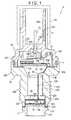
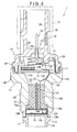
- Fig. 1 is a cross section of a pressure sensor of the first exemplary embodiment.
- the pressure sensor 1 is provided with: a joint 10 having a space formed therein; a diaphragm 11 (sensor element) provided on a first end of the joint 10; a housing 12 provided on a second end of the joint 10; a circuit board 13 provided within a space defined by the housing 12 and the joint 10; a flexible board 14 connected to the circuit board 13 and the diaphragm 11; and a terminal 15 supported by the housing 12.
- the joint 10 is a metal component having a series of: a hole 10A enlarging from a first end toward a second end thereof; a hole 10B having smaller diameter than the hole 10A; and a tapered hole 10C of which diameter increases toward the other end.
- An outer circumference of the joint 10 is provided with a screw 10D to be screwed into a pipe (not shown) in which to-be-measured fluid is flowed and a flange 10E formed on a side adjacent to the second end relative to the screw 10D.
- the flange 10E has an approximately cylindrical exterior portion 10F for crimping the housing 12. A distal end of the exterior portion 10F is bent toward the axial center of the joint 10.
- the diaphragm 11 is provided by a metal component, which includes: a cylindrical member 11A; a disk 11B provided on a first end of the cylindrical member 11A; and a flange 11C provided on an outer circumference of the cylindrical member 11A, the cylindrical member 11A, the disk 11B and the flange 11C being provided in an integrated manner.
- the to-be-measured fluid is introduced into a space provided inside the cylindrical member 11A and the disk 11B of the diaphragm 11.
- a measuring portion that detects the pressure by a strain gauge and the like is provided on a side of the disk 11B of the diaphragm 11 opposite to a side on which the to-be-measured fluid is introduced.
- a cap 16 is provided to cover an upper side of the measuring portion. The cap 16 is thermocompression-bonded to a first end of the flexible board 14.
- the end surface of the flange 11C and the first end of the joint 10 are airtightly bonded by welding and the like.
- the housing 12 is a synthetic resin component, which has a substantially bottomed-cylindrical base end 12A and a cylindrical distal end 12B integrated with the base end 12A.
- a periphery of the base end 12A is fitted into the exterior portion 10F of the joint 10.
- An O ring 17 is provided between the inner circumference of the exterior portion 10F and the outer circumference of the base end 12A.
- the terminal 15 is held by a disk 12C provided between the base end 12A and the distal end 12B.
- a gap d is provided between the terminal 15 and the disk 12C.
- the gap d is for adjusting the variable pressure within the space surrounded by the joint 10, the diaphragm 11 and the housing 12.
- the distal end 12B is adapted to be connected with a connector 18.
- An air-vent filter 19 that allows circulation of exterior air is provided on the distal end 12B at a position covered by the connector 18.
- the air-vent filter 19 satisfies both requirements of waterproof property and air permeability, which is substantially formed in a disk-shape.
- a recess 12D for the air-vent filter 19 to be fitted is provided on the outer circumference of the distal end 12B.
- An air-vent 12E is connected to the recess 12D.
- the circuit board 13 is sized so as to cover the opening of the hole 10C of the joint 10, both ends of which are supported on an end surface of the flange 10E with an attachment 13A.
- Electronic components 20 are mounted on the circuit board 13.
- a cut 13B is provided on an end of the circuit board 13.
- the flexible board 14 is inserted through the cut 13B.
- the flexible board 14 includes a first end 14A of which whole area is connected to the cap 16, a second end 14B connected to the circuit board 13 and a belt portion 14C that connects the first end 14A and the second end 14B.
- the first end 14A is electrically coupled with the diaphragm 11 by a bonding wire.
- a part of the belt portion 14C is fixed onto the joint 10 by an adhesive.
- the first end 14A of the flexible board 14 is formed substantially in a disc to cover the cap 16, on which a plurality of holes for wire-bonding and for attaching below-described cover are provided at predetermined positions.
- the second end 14B is a rectangular component to be connected with the circuitry of the circuit board 13.
- the recessed dents 14D to be engaged with the cut 13B of the circuit board 13 are respectively provided along both sides of the belt portion 14C.
- the belt portion 14C and the first end 14A are capable of being bent approximately at a right angle.
- a copper pattern 14E is formed on a side of the first end 14A, the belt portion 14C and the second end 14B,
- the terminal 15 is bent substantially in an L-shape.
- a first end 15A of the terminal 15 is supported by the housing 12 while a second end 15B thereof is electrically coupled with the circuit board 13.
- the bent portion of the terminal 15 is fixed on a case 21 that is attached to the flange 10E of the joint 10.
- a cover 22 that supports the flexible board 14 while being curved is attached on the cap 16.
- a board holder 23 for holding the flexible board 14 is attached on the cover 22.
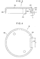
- Fig. 3 is a cross section of the cover 22
- Fig. 4 is a plan view of the cover 22
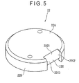
- Fig. 5 is a perspective view of the cover 22.
- the cover 22 is a substantially cap-shaped molded component of synthetic resin and the like, which includes a disk 22A, an outer circumference 22B integrally provided on the outer periphery of the disk 22A, an arc surface 22C provided by cutting a part of the outer circumference 22B and a leg 22D integrated with the disk 22A.
- the diameter of the outer circumference 22B is substantially the same as that of the hole 10A of the joint 10 (see Fig. 1 ).
- the arc surface 22C supports the flexible board 14 in a curved state, which includes a curved section 22Cl, a straight section 22C2 continuous with the curved section 22Cl and a curved section 22C3 continuous with the straight section 22C2.
- a dimension difference a between the distal end of the curved section 22C3 and the periphery of the outer circumference 22B is approximately the same as the thickness of the flexible board 14.
- the straight section 22C2 is recessed from the surface of the outer circumference 22B by a dimension b, which is substantially equal to the thickness of the flexible board 14.
- a width W of the arc surface 22C is substantially equal to a width of the belt portion 14F of the flexible board 14.
- the leg 22D protrudes from the periphery of the outer circumference 22B so that a distal end of the leg 22D can be fitted into a hole provided on the first end 14A of the flexible board 14.
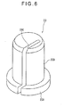
- Fig. 6 shows a specific construction of the board holder 23.
- the board holder 23 includes a base section 23A to be in contact with the disk 22A of the cover 22 and a column section 23B integrated with the base section 23A.
- the base section 23A is fitted into the hole 10A of the joint 10 and the column section 23B is fitted into the hole 10B. Accordingly, the board holder 23 is fixed within the joint 10.
- a slit 23C for the flexible board 14 to be inserted is provided on the board holder 23 at a position remote from the axial center of the board holder 23.
- the slit 23C extends in a direction away from the diaphragm 11 to hold the belt portion 14C of the flexible board 14.
- a depth of the slit 23C in the column section 23B is substantially equal to the width of the flexible board 14 and the gap dimension thereat is slightly larger than the thickness of the flexible board 14. Accordingly, a certain gap can be secured by the slit 23C even when the board holder 23 inserted into the flexible board 14 is fixed on the joint 10, thus tolerating pressure change within the cover 22.
- the board holder 23 is made of an elastic cushion material.
- the cushion material is, for instance, a molding component of a foam rubber.
- the first end 14A of the flexible board 14 and the cap 16 are thermocompression-bonded with an adhesive sheet and the cap 16 is fixed on the diaphragm 11 by laser-welding.
- the diaphragm 11 and the flexible board 14 are connected by wire-bonding using gold. Then, the cap 16 and the cover 22 are adhered and fixed by an adhesive.
- the belt portion 14C of the flexible board 14 is placed on the arc surface 22C of the cover 22 and is bent in an arc.
- the belt portion 14C of the flexible board 14 is bent substantially at a right angle in a direction reverse to that in the preceding bending. Then, the board holder 23 is assembled with the flexed belt portion 14C and is compressed to be inserted into the joint 10 (see Fig 1 ).
- the joint 10 and the diaphragm 11 are airtightly connected by an electron-beam welding, the circuit board 13 is fixed on the flange 10E of the joint 10 and the circuit board 13 and the flexible board 14 are soldered. At this time, the flexible board 14 is soldered while being bent in an arc.
- the case 21 and the terminal 15 are crimped.
- the terminal 15 and the circuit board 13 are connected by precision resistance welding the housing 12 assembled with the 0 ring 17 is inserted and the housing 12 is crimped to the joint 10.
- the board holders 23, 123 may not be provided in the exemplary embodiments.
- the specific construction thereof is not limited to those described in the exemplary embodiments.
- the material of the board holder may be hard synthetic resin or metal instead of urethane foam.
- metal since the board holder is disposed adjacent to or in contact with the copper pattern 14E of the flexible board 14, it is necessary that at least a part of the board holder to be in contact with the flexible board 14 is provided with nonconductive material.
- the invention is not applied limitatively to the pressure sensor, but may be applied to a differential-pressure sensor, temperature sensor and the like.
- cover 22 is attached to the cap 16
- the cover 22 of the invention may alternatively attached to the diaphragm 11.
Landscapes
- Physics & Mathematics (AREA)
- General Physics & Mathematics (AREA)
- Measuring Fluid Pressure (AREA)
Applications Claiming Priority (2)
| Application Number | Priority Date | Filing Date | Title |
|---|---|---|---|
| JP2007065164A JP4383461B2 (ja) | 2007-03-14 | 2007-03-14 | センサ及びセンサの製造方法 |
| JP2007079517A JP4431592B2 (ja) | 2007-03-26 | 2007-03-26 | センサ及びセンサの製造方法 |
Publications (2)
| Publication Number | Publication Date |
|---|---|
| EP1970687A2 true EP1970687A2 (fr) | 2008-09-17 |
| EP1970687A3 EP1970687A3 (fr) | 2010-07-07 |
Family
ID=39473946
Family Applications (1)
| Application Number | Title | Priority Date | Filing Date |
|---|---|---|---|
| EP08152805A Withdrawn EP1970687A3 (fr) | 2007-03-14 | 2008-03-14 | Capteur de pression et son procédé de fabrication |
Country Status (1)
| Country | Link |
|---|---|
| EP (1) | EP1970687A3 (fr) |
Cited By (2)
| Publication number | Priority date | Publication date | Assignee | Title |
|---|---|---|---|---|
| CN113108829A (zh) * | 2020-08-31 | 2021-07-13 | 杭州三花研究院有限公司 | 传感器组件 |
| CN115839787A (zh) * | 2022-12-13 | 2023-03-24 | 武汉飞恩微电子有限公司 | 一种压力测量组件及压力传感器 |
Citations (2)
| Publication number | Priority date | Publication date | Assignee | Title |
|---|---|---|---|---|
| JP2005326337A (ja) | 2004-05-17 | 2005-11-24 | Denso Corp | 圧力検出装置 |
| JP2006038824A (ja) | 2004-06-25 | 2006-02-09 | Nippon Seiki Co Ltd | 半導体センサ装置 |
Family Cites Families (1)
| Publication number | Priority date | Publication date | Assignee | Title |
|---|---|---|---|---|
| EP1455165A1 (fr) * | 2003-03-07 | 2004-09-08 | Intersema Sensoric SA | Capteur miniaturisé |
-
2008
- 2008-03-14 EP EP08152805A patent/EP1970687A3/fr not_active Withdrawn
Patent Citations (2)
| Publication number | Priority date | Publication date | Assignee | Title |
|---|---|---|---|---|
| JP2005326337A (ja) | 2004-05-17 | 2005-11-24 | Denso Corp | 圧力検出装置 |
| JP2006038824A (ja) | 2004-06-25 | 2006-02-09 | Nippon Seiki Co Ltd | 半導体センサ装置 |
Cited By (2)
| Publication number | Priority date | Publication date | Assignee | Title |
|---|---|---|---|---|
| CN113108829A (zh) * | 2020-08-31 | 2021-07-13 | 杭州三花研究院有限公司 | 传感器组件 |
| CN115839787A (zh) * | 2022-12-13 | 2023-03-24 | 武汉飞恩微电子有限公司 | 一种压力测量组件及压力传感器 |
Also Published As
| Publication number | Publication date |
|---|---|
| EP1970687A3 (fr) | 2010-07-07 |
Similar Documents
| Publication | Publication Date | Title |
|---|---|---|
| US7640812B2 (en) | Flexible board sensor and manufacturing method of sensor | |
| EP1970686B1 (fr) | Capteur de pression et son procédé de fabrication | |
| EP3805710B1 (fr) | Capteur de température et de pression combiné | |
| CN100434889C (zh) | 密封压力传感装置 | |
| KR100225330B1 (ko) | 반도체 센서 | |
| JP3870917B2 (ja) | 温度センサ一体型圧力センサ装置及びその温度センサ固定方法 | |
| TWI582399B (zh) | 壓力感測器及壓力感測器模組 | |
| EP2051298A1 (fr) | Boîtier de circuit intégré | |
| JP4301048B2 (ja) | 圧力センサおよびその製造方法 | |
| US7404328B2 (en) | Pressure sensor | |
| EP2889599A2 (fr) | Capteur de mesure de quantité physique et module de détection | |
| US6678164B2 (en) | Pressure sensor and method for manufacturing the same | |
| EP1970687A2 (fr) | Capteur de pression et son procédé de fabrication | |
| KR100405387B1 (ko) | 압전 공진기 | |
| KR102242428B1 (ko) | 스트레인 게이지 압력 센서 | |
| CN101297183A (zh) | 电子体温计 | |
| JP6373104B2 (ja) | 半導体圧力センサ及び半導体圧力センサ取付構造体 | |
| JP5050392B2 (ja) | 圧力センサ | |
| WO2019102737A1 (fr) | Débitmètre | |
| JP3871430B2 (ja) | 圧力センサ | |
| JP3700944B2 (ja) | 圧力センサ | |
| CN209606007U (zh) | 压力传感器 | |
| CN223107084U (zh) | 柔性线路传感器 | |
| JP2005326337A (ja) | 圧力検出装置 | |
| JP6476036B2 (ja) | 圧力センサ |
Legal Events
| Date | Code | Title | Description |
|---|---|---|---|
| PUAI | Public reference made under article 153(3) epc to a published international application that has entered the european phase |
Free format text: ORIGINAL CODE: 0009012 |
|
| AK | Designated contracting states |
Kind code of ref document: A2 Designated state(s): AT BE BG CH CY CZ DE DK EE ES FI FR GB GR HR HU IE IS IT LI LT LU LV MC MT NL NO PL PT RO SE SI SK TR |
|
| AX | Request for extension of the european patent |
Extension state: AL BA MK RS |
|
| PUAL | Search report despatched |
Free format text: ORIGINAL CODE: 0009013 |
|
| AK | Designated contracting states |
Kind code of ref document: A3 Designated state(s): AT BE BG CH CY CZ DE DK EE ES FI FR GB GR HR HU IE IS IT LI LT LU LV MC MT NL NO PL PT RO SE SI SK TR |
|
| AX | Request for extension of the european patent |
Extension state: AL BA MK RS |
|
| RIC1 | Information provided on ipc code assigned before grant |
Ipc: G01L 19/14 20060101ALI20100528BHEP Ipc: G01L 9/00 20060101AFI20100528BHEP |
|
| 17P | Request for examination filed |
Effective date: 20101005 |
|
| RAP1 | Party data changed (applicant data changed or rights of an application transferred) |
Owner name: NAGANO KEIKI CO., LTD. |
|
| AKX | Designation fees paid |
Designated state(s): AT BE BG CH CY CZ DE DK EE ES FI FR GB GR HR HU IE IS IT LI LT LU LV MC MT NL NO PL PT RO SE SI SK TR |
|
| STAA | Information on the status of an ep patent application or granted ep patent |
Free format text: STATUS: THE APPLICATION HAS BEEN WITHDRAWN |
|
| 18W | Application withdrawn |
Effective date: 20130110 |