EP1972480A2 - Installation hydraulique destinée à l'ouverture et la fermeture d'une capote de cabriolet - Google Patents
Installation hydraulique destinée à l'ouverture et la fermeture d'une capote de cabriolet Download PDFInfo
- Publication number
- EP1972480A2 EP1972480A2 EP08003914A EP08003914A EP1972480A2 EP 1972480 A2 EP1972480 A2 EP 1972480A2 EP 08003914 A EP08003914 A EP 08003914A EP 08003914 A EP08003914 A EP 08003914A EP 1972480 A2 EP1972480 A2 EP 1972480A2
- Authority
- EP
- European Patent Office
- Prior art keywords
- hydraulic
- valve
- connection
- actuator
- line
- Prior art date
- Legal status (The legal status is an assumption and is not a legal conclusion. Google has not performed a legal analysis and makes no representation as to the accuracy of the status listed.)
- Granted
Links
Images






Classifications
-
- F—MECHANICAL ENGINEERING; LIGHTING; HEATING; WEAPONS; BLASTING
- F15—FLUID-PRESSURE ACTUATORS; HYDRAULICS OR PNEUMATICS IN GENERAL
- F15B—SYSTEMS ACTING BY MEANS OF FLUIDS IN GENERAL; FLUID-PRESSURE ACTUATORS, e.g. SERVOMOTORS; DETAILS OF FLUID-PRESSURE SYSTEMS, NOT OTHERWISE PROVIDED FOR
- F15B11/00—Servomotor systems without provision for follow-up action; Circuits therefor
- F15B11/02—Systems essentially incorporating special features for controlling the speed or actuating force of an output member
- F15B11/04—Systems essentially incorporating special features for controlling the speed or actuating force of an output member for controlling the speed
- F15B11/046—Systems essentially incorporating special features for controlling the speed or actuating force of an output member for controlling the speed depending on the position of the working member
- F15B11/048—Systems essentially incorporating special features for controlling the speed or actuating force of an output member for controlling the speed depending on the position of the working member with deceleration control
-
- B—PERFORMING OPERATIONS; TRANSPORTING
- B60—VEHICLES IN GENERAL
- B60J—WINDOWS, WINDSCREENS, NON-FIXED ROOFS, DOORS, OR SIMILAR DEVICES FOR VEHICLES; REMOVABLE EXTERNAL PROTECTIVE COVERINGS SPECIALLY ADAPTED FOR VEHICLES
- B60J7/00—Non-fixed roofs; Roofs with movable panels, e.g. rotary sunroofs
- B60J7/02—Non-fixed roofs; Roofs with movable panels, e.g. rotary sunroofs of sliding type, e.g. comprising guide shoes
- B60J7/04—Non-fixed roofs; Roofs with movable panels, e.g. rotary sunroofs of sliding type, e.g. comprising guide shoes with rigid plate-like element or elements, e.g. open roofs with harmonica-type folding rigid panels
- B60J7/057—Driving or actuating arrangements e.g. manually operated levers or knobs
- B60J7/0573—Driving or actuating arrangements e.g. manually operated levers or knobs power driven arrangements, e.g. electrical
- B60J7/0576—Driving or actuating arrangements e.g. manually operated levers or knobs power driven arrangements, e.g. electrical fluid
-
- B—PERFORMING OPERATIONS; TRANSPORTING
- B60—VEHICLES IN GENERAL
- B60J—WINDOWS, WINDSCREENS, NON-FIXED ROOFS, DOORS, OR SIMILAR DEVICES FOR VEHICLES; REMOVABLE EXTERNAL PROTECTIVE COVERINGS SPECIALLY ADAPTED FOR VEHICLES
- B60J7/00—Non-fixed roofs; Roofs with movable panels, e.g. rotary sunroofs
- B60J7/08—Non-fixed roofs; Roofs with movable panels, e.g. rotary sunroofs of non-sliding type, i.e. movable or removable roofs or panels, e.g. let-down tops or roofs capable of being easily detached or of assuming a collapsed or inoperative position
- B60J7/12—Non-fixed roofs; Roofs with movable panels, e.g. rotary sunroofs of non-sliding type, i.e. movable or removable roofs or panels, e.g. let-down tops or roofs capable of being easily detached or of assuming a collapsed or inoperative position foldable; Tensioning mechanisms therefor, e.g. struts
- B60J7/1226—Soft tops for convertible vehicles
- B60J7/1265—Soft tops for convertible vehicles characterised by kinematic movements, e.g. using parallelogram linkages
- B60J7/1269—Soft tops for convertible vehicles characterised by kinematic movements, e.g. using parallelogram linkages with remote power control
- B60J7/1273—Soft tops for convertible vehicles characterised by kinematic movements, e.g. using parallelogram linkages with remote power control using hydraulic means
-
- F—MECHANICAL ENGINEERING; LIGHTING; HEATING; WEAPONS; BLASTING
- F15—FLUID-PRESSURE ACTUATORS; HYDRAULICS OR PNEUMATICS IN GENERAL
- F15B—SYSTEMS ACTING BY MEANS OF FLUIDS IN GENERAL; FLUID-PRESSURE ACTUATORS, e.g. SERVOMOTORS; DETAILS OF FLUID-PRESSURE SYSTEMS, NOT OTHERWISE PROVIDED FOR
- F15B2211/00—Circuits for servomotor systems
- F15B2211/30—Directional control
- F15B2211/305—Directional control characterised by the type of valves
- F15B2211/30505—Non-return valves, i.e. check valves
- F15B2211/30515—Load holding valves
-
- F—MECHANICAL ENGINEERING; LIGHTING; HEATING; WEAPONS; BLASTING
- F15—FLUID-PRESSURE ACTUATORS; HYDRAULICS OR PNEUMATICS IN GENERAL
- F15B—SYSTEMS ACTING BY MEANS OF FLUIDS IN GENERAL; FLUID-PRESSURE ACTUATORS, e.g. SERVOMOTORS; DETAILS OF FLUID-PRESSURE SYSTEMS, NOT OTHERWISE PROVIDED FOR
- F15B2211/00—Circuits for servomotor systems
- F15B2211/30—Directional control
- F15B2211/305—Directional control characterised by the type of valves
- F15B2211/3052—Shuttle valves
-
- F—MECHANICAL ENGINEERING; LIGHTING; HEATING; WEAPONS; BLASTING
- F15—FLUID-PRESSURE ACTUATORS; HYDRAULICS OR PNEUMATICS IN GENERAL
- F15B—SYSTEMS ACTING BY MEANS OF FLUIDS IN GENERAL; FLUID-PRESSURE ACTUATORS, e.g. SERVOMOTORS; DETAILS OF FLUID-PRESSURE SYSTEMS, NOT OTHERWISE PROVIDED FOR
- F15B2211/00—Circuits for servomotor systems
- F15B2211/30—Directional control
- F15B2211/305—Directional control characterised by the type of valves
- F15B2211/3056—Assemblies of multiple valves
- F15B2211/30565—Assemblies of multiple valves having multiple valves for a single output member, e.g. for creating higher valve function by use of multiple valves like two 2/2-valves replacing a 5/3-valve
- F15B2211/3057—Assemblies of multiple valves having multiple valves for a single output member, e.g. for creating higher valve function by use of multiple valves like two 2/2-valves replacing a 5/3-valve having two valves, one for each port of a double-acting output member
-
- F—MECHANICAL ENGINEERING; LIGHTING; HEATING; WEAPONS; BLASTING
- F15—FLUID-PRESSURE ACTUATORS; HYDRAULICS OR PNEUMATICS IN GENERAL
- F15B—SYSTEMS ACTING BY MEANS OF FLUIDS IN GENERAL; FLUID-PRESSURE ACTUATORS, e.g. SERVOMOTORS; DETAILS OF FLUID-PRESSURE SYSTEMS, NOT OTHERWISE PROVIDED FOR
- F15B2211/00—Circuits for servomotor systems
- F15B2211/30—Directional control
- F15B2211/315—Directional control characterised by the connections of the valve or valves in the circuit
-
- F—MECHANICAL ENGINEERING; LIGHTING; HEATING; WEAPONS; BLASTING
- F15—FLUID-PRESSURE ACTUATORS; HYDRAULICS OR PNEUMATICS IN GENERAL
- F15B—SYSTEMS ACTING BY MEANS OF FLUIDS IN GENERAL; FLUID-PRESSURE ACTUATORS, e.g. SERVOMOTORS; DETAILS OF FLUID-PRESSURE SYSTEMS, NOT OTHERWISE PROVIDED FOR
- F15B2211/00—Circuits for servomotor systems
- F15B2211/30—Directional control
- F15B2211/35—Directional control combined with flow control
- F15B2211/353—Flow control by regulating means in return line, i.e. meter-out control
-
- F—MECHANICAL ENGINEERING; LIGHTING; HEATING; WEAPONS; BLASTING
- F15—FLUID-PRESSURE ACTUATORS; HYDRAULICS OR PNEUMATICS IN GENERAL
- F15B—SYSTEMS ACTING BY MEANS OF FLUIDS IN GENERAL; FLUID-PRESSURE ACTUATORS, e.g. SERVOMOTORS; DETAILS OF FLUID-PRESSURE SYSTEMS, NOT OTHERWISE PROVIDED FOR
- F15B2211/00—Circuits for servomotor systems
- F15B2211/70—Output members, e.g. hydraulic motors or cylinders or control therefor
- F15B2211/705—Output members, e.g. hydraulic motors or cylinders or control therefor characterised by the type of output members or actuators
- F15B2211/7051—Linear output members
- F15B2211/7053—Double-acting output members
-
- F—MECHANICAL ENGINEERING; LIGHTING; HEATING; WEAPONS; BLASTING
- F15—FLUID-PRESSURE ACTUATORS; HYDRAULICS OR PNEUMATICS IN GENERAL
- F15B—SYSTEMS ACTING BY MEANS OF FLUIDS IN GENERAL; FLUID-PRESSURE ACTUATORS, e.g. SERVOMOTORS; DETAILS OF FLUID-PRESSURE SYSTEMS, NOT OTHERWISE PROVIDED FOR
- F15B2211/00—Circuits for servomotor systems
- F15B2211/70—Output members, e.g. hydraulic motors or cylinders or control therefor
- F15B2211/71—Multiple output members, e.g. multiple hydraulic motors or cylinders
- F15B2211/7114—Multiple output members, e.g. multiple hydraulic motors or cylinders with direct connection between the chambers of different actuators
- F15B2211/7128—Multiple output members, e.g. multiple hydraulic motors or cylinders with direct connection between the chambers of different actuators the chambers being connected in parallel
Definitions
- the invention relates to a hydraulic system for opening and closing a convertible top, which comprises a plurality of independently movable components, including a roof and a storage space cover, under which the roof is stowed in the open state.
- the hydraulic systems must be able to move the individual components in a defined order so that the roof is stored collision-free.
- the roof In the case of a hardtop, the roof is usually stowed under the boot lid.
- the roof In the case of a fabric roof, the roof is stowed under a top compartment lid.
- a clamping bracket is present to clamp the fabric top in the closed state, so that here - as in the case of multi-part hard tops - is usually the movement of at least three moving components to coordinate.
- the movement of the individual components takes place by means of actuators, wherein an actuator for each component is usually present on each side of the vehicle.
- the actuators are controlled by means of electrically operable two-position valves, conventionally two valves per actuator pair are present.
- these valves are expensive, so that a fundamental concern is to keep the number of valves low.
- the EP 1 046 533 A1 deals in particular with the problem of proposing an automatic "emergency operation function" while maintaining a “hold function” while further reducing the necessary valves.
- the holding function should ensure that the movement of the top unit at any moment temporarily set and hold in the current position.
- the emergency operation function is intended to open the possibility of manually moving the top unit in the open and in the closed state when the electrically driven pump and / or electrically operated valves do not function due to an electrical fault.
- This is in the EP 1 046 533 A1 realized by a combination of multiple check valves before single or all switching valves in combination with an OR valve.
- the check valves serve the holding function and the OR valve of the emergency operation function.
- the OR valve is connected in the regeneratively operated actuators to that side of the differential piston at which no switching valve is provided.
- the piston On the opposite side of the differential piston, so the side with switching valve, the piston is depressurized by the fact that the relevant switching valve in non-activated position leads to the tank.
- this side is guided via the OR valve either with one or with the other switching valve of the serving for roof movement actuator. Because this actuator has its own because of the high forces required to close the roof for each side of the piston. Switch valve, but both lead to the tank in case of power failure, so that the OR valve in case of power failure in each case establishes a connection to the tank.
- proportional valves are used. Such proportional valves are necessary for each regulated circuit.
- a proportional valve, as it is also usable in connection with the present invention is, for example in the WO 2004/036057 A2 described.
- Object of the present invention is therefore to provide a hydraulic system for opening and closing a convertible top with several independently to propose movable components, which allows the regulation of the speed of the individual components and manages with little proportional valves.
- both the roof and the storage space cover can be retracted braked in their respective closed position by the return flow of the hydraulic fluid from the actuators via the OR valve back to the tank via the proportional valve is individually throttled ,
- This is of particular importance in order to protect the locking mechanisms by means of which the roof or the storage space cover are locked in their respective closed position.
- unrestrained retraction is not critical, since no here Locking mechanism is to spare.
- the components drive here for example, against rubber buffers or in the case of a fabric hood results in a sufficient damping already by the autonomous folding of the top fabric.
- valves are all or at least as far as possible realized as simple electrically operable two-position valves, that is to say those valves which assume only shift end positions.
- the hydraulic system according to the invention is not limited to the fact that individual actuators are operated regeneratively. Rather, the inventive interconnection of the hydraulic lines offers the same advantage of a reduced number of proportional valves, even if individual or all actuators are controlled via two switching valves.
- the OR valve of the hydraulic system according to the invention may be an electrically actuated 3/2-way switching valve, so that it can be actively specified which of two possible connections makes the OR valve to return a reflux of the hydraulic fluid when closing the roof or the storage space cover to lead to the tank via the proportional valve.
- the OR valve is a passive component, which is cheaper than a 3/2-way switching valve and requires no electronic control.
- the position of a passive OR valve is rather determined by the differential pressure of two hydraulic lines, to which the OR valve should connect, the connection always being made to the higher pressure hydraulic line.
- the OR valve has a preferred position, which is functionally designed so that the OR valve in its preferred position establishes a connection to the proportional valve.
- the OR valve can be held by spring preload in its preferred position.
- the inventive interconnection of the hydraulic lines via the OR valve has the advantage that the return flow of the hydraulic fluid from the actuators of different hydraulic circuits back into the Tank always via the one proportional valve takes place when the actuators drive to their lockable end position.
- FIG. 1A shows a hydraulic scheme according to a first embodiment with a roof and a boot lid are independently displaceable between a closed and an open position.
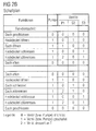
- FIG. 1B shows a flow chart, which shows the order in which the valves P1 and S2 of the hydraulic system are to be switched to open the one hand, the closed roof and stowed under the boot lid and on the other hand to move the roof under the boot lid in the closed position ,
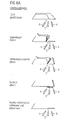
- FIGS. 3A and 3B These movements are illustrated schematically. Consequently, the hydraulic system is particularly suitable for coordinating a hardtop convertible top when opening and closing in such a way with the movement of a boot lid, that the roof does not collide with the rear lid when driving in and out.
- the hydraulic system comprises in a conventional manner a motor-driven pump P and a tank T or oil sump, from which the pump sucks the hydraulic fluid and in which the hydraulic fluid flows back out of the system.
- the hydraulic system further comprises in the illustrated first embodiment, two hydraulic circuits, namely a first hydraulic circuit with two actuators A for moving the roof and a second hydraulic circuit with two actuators B for moving the rear lid.
- the two actuators A and the two actuators B are each connected in parallel. It can also be provided more than two parallel actuators per hydraulic circuit or, for example, only a single actuator. The actuators are therefore also described in the singular.
- the actuators A and B are shown here for the sake of simplicity as simple linear piston actuators, which are designed as differential pistons. Other hydraulic actuators can be used in the same way. It is crucial in the context of the present invention alone that the actuators each comprise a first and a second hydraulic connection in order to move the actuator or its piston in opposite directions.
- the first hydraulic circuit for moving the roof comprises a proportional valve P1 and a 3/2 switching valve S2.
- the proportional valve P1 is connected via a first hydraulic line 10 to a first hydraulic port 11 of the actuator A and the switching valve S2 is connected via a second hydraulic line 20 to a second hydraulic port 12 of the same actuator A.
- Both valves P1 and S2 are electrically actuated, spring-return valves, via which the hydraulic connections 11 and 12 can be connected either independently to the pump connection or to the tank connection.
- the 3/2-way valve S2 the return to the tank is throttled by a fixed throttle.
- the proportional valve P1 is designed as a multi-position valve such that the throttling to the tank is adjustable via a solenoid coil current.
- Such a valve is for example in the WO 2004/036057 A2 described. It has 3 connections with a first position, which is connected to the pump with the tank return blocked, a second position, where the connection to the pump is blocked and the tank return is open, and any number of other positions, where a connection to the pump also locked and the tank return is throttled individually.
- the roof is closed, that is to say when the switching valve S2 is switched or activated, the return flow of the hydraulic fluid from the actuator A is through the first Hydraulic connection 11 and further influenced by the proportional valve P1 back to the tank by means of the variably adjustable throttling of the proportional valve P1 exactly.
- the retraction of the actuator in the locking position of the closed roof can thereby slow targeted and protect the locking mechanism in the roof stops accordingly.
- the second hydraulic circuit for moving the boot lid by means of the actuators B has no own switching valves in this embodiment. Instead, the two valves P1 and S2 are also used for the second hydraulic circuit through the use of an OR valve OV with preferred position.
- the OR valve connects the two hydraulic lines 10 and 20 of the first hydraulic circuit to each other such that a third hydraulic line 30 leading to a second hydraulic port 14 of the actuator B, either via the first hydraulic line 10 to the proportional valve P1 or via the second hydraulic line 20th is connected to the switching valve S2.
- the extension of the actuator B or opening the boot lid is then done by switching one of the valves P1 or S2.
- a fourth hydraulic line 40 leads from a first hydraulic connection 13 of the actuator B to the pumping line 50. That is, the actuator B is operated regeneratively in this first embodiment.
- the differential piston of the actuator B is extended, whereby the boot lid is transferred from the closed to the open state.
- the displaced by the first hydraulic port 13 of the actuator B hydraulic fluid does not flow back to the tank T, but is fed into the pumping line P. It is thus a regeneratively operated actuator, which only works in the manner described, because due to the design of the piston as a differential piston displaced by the first hydraulic connection 13 hydraulic fluid amount is smaller than the amount supplied by the second hydraulic connection 14. It should be noted that with actively switched switching valve S2 not only the boot lid is moved to its open position, but at the same time the roof is pressed by means of the actuator A in its already closed end position.
- the roof is opened. That is, the roof is unlocked and then moved by the actuator A from its closed to its open position by the proportional valve P1 is activated.
- the OR valve switches and establishes a connection between the second hydraulic connection 14 of the actuator B and the pumping line 50 via the proportional valve P1.
- the switching valve S2 is not switched to current-free, ie inactive, when the proportional valve P1 has been activated. Because of it it is ensured that the second hydraulic connection 14 of the actuator B is constantly connected to the pump line 50 when the boot lid is open.
- the boot lid is closed again.
- the proportional valve P1 is initially completely de-energized, ie switched inactive.
- the boot lid is braked by the proportional valve P1 is partially energized. This throttles the tank return. With increasing current, the throttling increases.
- the proportional valve P1 is then completely de-energized, and the boot lid can be locked.
- the OR valve OV is in a position in which it establishes a flow connection between the second hydraulic port 14 of the actuator B and the valve P open to the proportional valve P1.
- this is achieved by virtue of the fact that the OR valve OV has a preferred position which ensures precisely this flow connection when, as in the situation described, the other switching valve S2 is open to the tank.
- an active, electrical switchable valve can be used as an OR valve.
- a passive OR valve is preferable because of its simple construction. The preferred position can be realized for example by means of a spring preload. In the FIGS. 7A and 7B two variants of such a passive OR valve with spring preset preferred position are shown schematically.
- the roof is opened in the reverse way.
- the boot lid is opened, but this time by activating the proportional valve P1, as this ensures that the roof is pressed during the opening of the boot lid in its open end position or held there. If the boot lid were opened via the switching valve S2, so would the roof at the same time raised from its open position to its closed position and thereby collide with the boot lid.
- the roof is opened by the proportional valve P1 de-energized, ie inactive and again the switching valve S2 is activated. Again, it is expedient to switch the switching valve S2 active before the proportional valve P1 is switched inactive in order to avoid a hydraulic pulse on the boot lid.
- the OR valve also switches, so that the boot lid is simultaneously pressed and held in its open position when closing the roof.
- the proportional valve P1 is again partially energized to throttle the return flow in the tank T and thereby slow down the closing movement in its final position, whereby an unrestrained retraction against the locking mechanism can be avoided.
- the proportional valve P1 is completely de-energized and the switching valve S2 is de-energized.
- the boot lid is thereby moved from its open to its closed position. Shortly before reaching the end position, the rear lid movement is braked by the proportional valve P1 partially energized and thereby throttling of the flowing into the tank line 60 hydraulic fluid is achieved.
- the boot lid can be locked in the closed position and the proportional valve P1 can be deactivated.
- FIG. 2A shows a second embodiment of a modified embodiment of the first embodiment.
- the actuators B of the second circuit are not operated regeneratively, but instead that a further switching valve S3 is provided, via which the displaced by the first hydraulic connection 13 from the actuator B hydraulic fluid to the tank line 60 and on to the tank T. can be returned.
- This offers the advantage that greater forces can be realized by means of the actuator B when opening the boot lid but has the disadvantage that the additional switching valve S3 including the associated wiring and control electronics is required.
- FIG. 2B shows the hydraulic scheme according to FIG. 2A the chronological sequence of the switching positions of the three valves P1, S2 and S3. Unlike the schedule after FIG. 1B follows from the schedule FIG. 2B in that the additional switching valve S3 is only activated when the boot lid is moved from its open condition to its closed condition. Otherwise it is open to tank T.
- FIG. 4A shows a third embodiment according to another modified embodiment of the first embodiment.
- a third hydraulic circuit with actuators C is present.
- the third hydraulic circuit is connected to the same pumping line 50 and tank line 60 as the first and second hydraulic circuits having their actuators A and B, respectively.
- the actuators C of the third hydraulic circuit are not connected through the valves P1 and S2 the first hydraulic circuit controlled.
- two separate switching valves S4 and S5 are provided, which are preferably designed identically as the switching valve S2, ie as an electromagnetically actuated 3/2 valve with spring return, in particular as a ball seat valve and preferably with tank-side throttling.
- the actuator C of the third hydraulic circuit can be operated regeneratively, in which case the switching valve S4 can be omitted and the relevant hydraulic line is connected to the pumping line 50.
- the third hydraulic circuit with the actuators C can serve, for example, to move a third part of the convertible top independently of the other parts of the convertible top.
- a hydraulic system is suitable for a convertible top made of fabric, which has an additional movable part a clamping bracket for tensioning the fabric top in the closed top condition. This clamp can then be moved by means of the actuators C of the third hydraulic circuit.
- FIG. 4B shows a suitable schedule.
- This schedule differs from the schedule FIG. 1B only by the two function steps “lift clamp” and “lower clamp” both when opening the roof and when closing the roof.
- the function step “lower clamping bracket” omitted or limited to a short abutment of the clamping bracket movement, since the clamping bracket gravity due and in conjunction with the hood anyway lowers automatically.
- the switching valve S5 is activated when closing the roof before and during the opening of the top compartment lid (VDKD) to lift the clamp and hold in the raised position. Subsequently, the switching valve S5 is switched inactive and, if appropriate, the switching valve S4 is activated for a short time in order to initiate the lowering of the tensioning bow.
- the functional steps in opening the roof are exactly as described above with reference to the first embodiment.
- the top clearance at the top shelf and when closing the top is in its individual steps in the FIGS. 6A or 6B shown schematically.
- FIG. 5A shows as a fourth embodiment, a further modification, which basically forms a combination of the second and the third embodiment. That is, even in the fourth embodiment, a third hydraulic circuit with the already explained for the third embodiment switching valves S4 and S5 is provided. In addition, the actuators B of the third hydraulic circuit are not operated regeneratively, as in the first and third embodiments, but instead a second switching valve S3 is present in the second hydraulic circuit, as already explained in connection with the second embodiment. A more detailed description of this fourth embodiment is therefore unnecessary. In particular, the switching valve S3 is activated only during the closing operation of the top compartment lid (VDKD), as well as the extended schedule according to FIG. 5B it is not otherwise apparent from the schedule FIG. 4B different.
- VDKD top compartment lid
Landscapes
- Engineering & Computer Science (AREA)
- Mechanical Engineering (AREA)
- Physics & Mathematics (AREA)
- Fluid Mechanics (AREA)
- General Engineering & Computer Science (AREA)
- Fluid-Pressure Circuits (AREA)
- Power-Operated Mechanisms For Wings (AREA)
- Fluid-Driven Valves (AREA)
Applications Claiming Priority (1)
| Application Number | Priority Date | Filing Date | Title |
|---|---|---|---|
| DE200710013015 DE102007013015B4 (de) | 2007-03-19 | 2007-03-19 | Hydraulikanlage zum Öffnen und Schließen eines Cabrioverdecks |
Publications (3)
| Publication Number | Publication Date |
|---|---|
| EP1972480A2 true EP1972480A2 (fr) | 2008-09-24 |
| EP1972480A3 EP1972480A3 (fr) | 2012-06-27 |
| EP1972480B1 EP1972480B1 (fr) | 2013-12-04 |
Family
ID=39535339
Family Applications (1)
| Application Number | Title | Priority Date | Filing Date |
|---|---|---|---|
| EP08003914.2A Ceased EP1972480B1 (fr) | 2007-03-19 | 2008-02-29 | Installation hydraulique destinée à l'ouverture et la fermeture d'une capote de cabriolet |
Country Status (2)
| Country | Link |
|---|---|
| EP (1) | EP1972480B1 (fr) |
| DE (1) | DE102007013015B4 (fr) |
Families Citing this family (3)
| Publication number | Priority date | Publication date | Assignee | Title |
|---|---|---|---|---|
| DE102009011303B4 (de) * | 2009-03-02 | 2015-10-08 | Webasto Ag | Vorrichtung zur Ventilansteuerung für ein Verdecksystem eines Fahrzeugs und zugehöriges Verfahren |
| DE102010038315B4 (de) * | 2010-07-23 | 2015-09-24 | Rausch & Pausch Gmbh | Hydraulikanlage zum Bewegen eines Verdeckteils eines Cabrioverdecks |
| DE102014018357A1 (de) | 2014-12-11 | 2015-06-18 | Daimler Ag | Schutzeinrichtung für ein Verdeck eines offenen Kraftwagens und Verfahren zum Verstellen des Verdecks |
Citations (2)
| Publication number | Priority date | Publication date | Assignee | Title |
|---|---|---|---|---|
| EP1046533A1 (fr) | 1999-04-21 | 2000-10-25 | Applied Power Inc. | Système de contrôle hydraulique pour capote flexible de véhicule |
| WO2004036057A2 (fr) | 2002-10-15 | 2004-04-29 | Rausch & Pausch Gmbh | Electrovanne regulable |
Family Cites Families (2)
| Publication number | Priority date | Publication date | Assignee | Title |
|---|---|---|---|---|
| KR100312022B1 (ko) * | 1993-12-03 | 2001-12-28 | 안토니 더블유. 아스무스, 더 써드 | 유압 회로 |
| DE19959560C2 (de) * | 1999-12-10 | 2003-08-07 | Karmann Gmbh W | Hydraulische Schaltungsvorrichtung |
-
2007
- 2007-03-19 DE DE200710013015 patent/DE102007013015B4/de not_active Expired - Fee Related
-
2008
- 2008-02-29 EP EP08003914.2A patent/EP1972480B1/fr not_active Ceased
Patent Citations (2)
| Publication number | Priority date | Publication date | Assignee | Title |
|---|---|---|---|---|
| EP1046533A1 (fr) | 1999-04-21 | 2000-10-25 | Applied Power Inc. | Système de contrôle hydraulique pour capote flexible de véhicule |
| WO2004036057A2 (fr) | 2002-10-15 | 2004-04-29 | Rausch & Pausch Gmbh | Electrovanne regulable |
Also Published As
| Publication number | Publication date |
|---|---|
| DE102007013015A1 (de) | 2008-09-25 |
| DE102007013015B4 (de) | 2014-09-04 |
| EP1972480A3 (fr) | 2012-06-27 |
| EP1972480B1 (fr) | 2013-12-04 |
Similar Documents
| Publication | Publication Date | Title |
|---|---|---|
| EP3080461B1 (fr) | Valve | |
| DE10330805B4 (de) | Luftfahrzeug-Fahrwerksbetätigung | |
| EP2115305B1 (fr) | Entraînement hydraulique, en particulier pour machines-outils, et procédé pour commander l'entraînement hydraulique | |
| AT403785B (de) | Hydraulische betätigungsanordnung | |
| DE60014685T2 (de) | Hydraulisches system für flugzeugfahrwerk | |
| EP2294331B1 (fr) | Dispositif de vanne hydraulique | |
| DE102015117004B3 (de) | Bewegungseinrichtung für Schubladen | |
| AT396613B (de) | Hydraulische betätigungsanordnung für ein fahrzeugverdeck | |
| EP1972480B1 (fr) | Installation hydraulique destinée à l'ouverture et la fermeture d'une capote de cabriolet | |
| AT406072B (de) | Hydraulische betätigungsanordnung | |
| EP0975856A1 (fr) | Dispositif de commande hydraulique pour au moins une soupape de cylindre | |
| DE2164728A1 (de) | Schaltschieberanordnung | |
| AT410821B (de) | Betätigungsanordnung für um eine drehachse schwenkbare teile an fahrzeugen | |
| DE102013100002B4 (de) | Antriebseinrichtung für eine Flügeltür eines Busses | |
| EP1106840B1 (fr) | Circuit hydraulique | |
| AT408331B (de) | Betätigungsanordnung für bewegte teile an fahrzeugen, insbesondere heckdeckel, verdeckklappen, motorhauben od.dgl. | |
| EP2349762A1 (fr) | Dispositif d'actionnement hydraulique pour une unité de toit d'un véhicule | |
| DE102010038315B4 (de) | Hydraulikanlage zum Bewegen eines Verdeckteils eines Cabrioverdecks | |
| EP2541071B1 (fr) | Agencement de soupapes pour un système de commande hydraulique | |
| WO2006084445A2 (fr) | Porte comprenant un frein de porte | |
| EP1419910B1 (fr) | Suspension hydropneumatique | |
| DE102017102307B3 (de) | Kraftfahrzeug mit offener Fahrgastzelle | |
| AT412810B (de) | Bremsventil, insbesonders für hydraulische betätigungsanordnungen für bewegbare teile an fahrzeugen | |
| DE102008059560B4 (de) | Hydraulikanlage zum Betätigen einer Cabrioverdeckeinrichtung | |
| AT409112B (de) | Hydraulische anordnung zur betätigung von beweglichen teilen an fahrzeugen, und vorspannventil für diese anordnung |
Legal Events
| Date | Code | Title | Description |
|---|---|---|---|
| PUAI | Public reference made under article 153(3) epc to a published international application that has entered the european phase |
Free format text: ORIGINAL CODE: 0009012 |
|
| AK | Designated contracting states |
Kind code of ref document: A2 Designated state(s): AT BE BG CH CY CZ DE DK EE ES FI FR GB GR HR HU IE IS IT LI LT LU LV MC MT NL NO PL PT RO SE SI SK TR |
|
| AX | Request for extension of the european patent |
Extension state: AL BA MK RS |
|
| PUAL | Search report despatched |
Free format text: ORIGINAL CODE: 0009013 |
|
| AK | Designated contracting states |
Kind code of ref document: A3 Designated state(s): AT BE BG CH CY CZ DE DK EE ES FI FR GB GR HR HU IE IS IT LI LT LU LV MC MT NL NO PL PT RO SE SI SK TR |
|
| AX | Request for extension of the european patent |
Extension state: AL BA MK RS |
|
| RIC1 | Information provided on ipc code assigned before grant |
Ipc: F15B 11/048 20060101ALI20120524BHEP Ipc: B60J 7/057 20060101ALI20120524BHEP Ipc: B60J 7/12 20060101AFI20120524BHEP |
|
| 17P | Request for examination filed |
Effective date: 20121205 |
|
| AKX | Designation fees paid |
Designated state(s): DE GB IT NL |
|
| GRAP | Despatch of communication of intention to grant a patent |
Free format text: ORIGINAL CODE: EPIDOSNIGR1 |
|
| INTG | Intention to grant announced |
Effective date: 20130411 |
|
| GRAS | Grant fee paid |
Free format text: ORIGINAL CODE: EPIDOSNIGR3 |
|
| GRAP | Despatch of communication of intention to grant a patent |
Free format text: ORIGINAL CODE: EPIDOSNIGR1 |
|
| INTG | Intention to grant announced |
Effective date: 20130913 |
|
| GRAA | (expected) grant |
Free format text: ORIGINAL CODE: 0009210 |
|
| AK | Designated contracting states |
Kind code of ref document: B1 Designated state(s): DE GB IT NL |
|
| REG | Reference to a national code |
Ref country code: GB Ref legal event code: FG4D Free format text: NOT ENGLISH |
|
| REG | Reference to a national code |
Ref country code: DE Ref legal event code: R096 Ref document number: 502008011015 Country of ref document: DE Effective date: 20140130 |
|
| REG | Reference to a national code |
Ref country code: NL Ref legal event code: VDEP Effective date: 20131204 |
|
| PG25 | Lapsed in a contracting state [announced via postgrant information from national office to epo] |
Ref country code: NL Free format text: LAPSE BECAUSE OF FAILURE TO SUBMIT A TRANSLATION OF THE DESCRIPTION OR TO PAY THE FEE WITHIN THE PRESCRIBED TIME-LIMIT Effective date: 20131204 |
|
| REG | Reference to a national code |
Ref country code: DE Ref legal event code: R097 Ref document number: 502008011015 Country of ref document: DE |
|
| PLBE | No opposition filed within time limit |
Free format text: ORIGINAL CODE: 0009261 |
|
| STAA | Information on the status of an ep patent application or granted ep patent |
Free format text: STATUS: NO OPPOSITION FILED WITHIN TIME LIMIT |
|
| 26N | No opposition filed |
Effective date: 20140905 |
|
| GBPC | Gb: european patent ceased through non-payment of renewal fee |
Effective date: 20140304 |
|
| REG | Reference to a national code |
Ref country code: DE Ref legal event code: R097 Ref document number: 502008011015 Country of ref document: DE Effective date: 20140905 |
|
| PG25 | Lapsed in a contracting state [announced via postgrant information from national office to epo] |
Ref country code: GB Free format text: LAPSE BECAUSE OF NON-PAYMENT OF DUE FEES Effective date: 20140304 |
|
| PG25 | Lapsed in a contracting state [announced via postgrant information from national office to epo] |
Ref country code: IT Free format text: LAPSE BECAUSE OF FAILURE TO SUBMIT A TRANSLATION OF THE DESCRIPTION OR TO PAY THE FEE WITHIN THE PRESCRIBED TIME-LIMIT Effective date: 20131204 |
|
| REG | Reference to a national code |
Ref country code: DE Ref legal event code: R082 Ref document number: 502008011015 Country of ref document: DE Representative=s name: KLUNKER IP PATENTANWAELTE PARTG MBB, DE |
|
| PGFP | Annual fee paid to national office [announced via postgrant information from national office to epo] |
Ref country code: DE Payment date: 20190425 Year of fee payment: 12 |
|
| REG | Reference to a national code |
Ref country code: DE Ref legal event code: R119 Ref document number: 502008011015 Country of ref document: DE |
|
| PG25 | Lapsed in a contracting state [announced via postgrant information from national office to epo] |
Ref country code: DE Free format text: LAPSE BECAUSE OF NON-PAYMENT OF DUE FEES Effective date: 20200901 |
|
| P01 | Opt-out of the competence of the unified patent court (upc) registered |
Effective date: 20230522 |
|
| P02 | Opt-out of the competence of the unified patent court (upc) corrected |
Effective date: 20230601 |