EP1972728A2 - Spültoilette - Google Patents
Spültoilette Download PDFInfo
- Publication number
- EP1972728A2 EP1972728A2 EP08004063A EP08004063A EP1972728A2 EP 1972728 A2 EP1972728 A2 EP 1972728A2 EP 08004063 A EP08004063 A EP 08004063A EP 08004063 A EP08004063 A EP 08004063A EP 1972728 A2 EP1972728 A2 EP 1972728A2
- Authority
- EP
- European Patent Office
- Prior art keywords
- pump assembly
- fluid
- bowl
- valve
- pump
- Prior art date
- Legal status (The legal status is an assumption and is not a legal conclusion. Google has not performed a legal analysis and makes no representation as to the accuracy of the status listed.)
- Withdrawn
Links
Images




Classifications
-
- E—FIXED CONSTRUCTIONS
- E03—WATER SUPPLY; SEWERAGE
- E03D—WATER-CLOSETS OR URINALS WITH FLUSHING DEVICES; FLUSHING VALVES THEREFOR
- E03D5/00—Special constructions of flushing devices, e.g. closed flushing system
- E03D5/01—Special constructions of flushing devices, e.g. closed flushing system using flushing pumps
-
- F—MECHANICAL ENGINEERING; LIGHTING; HEATING; WEAPONS; BLASTING
- F04—POSITIVE - DISPLACEMENT MACHINES FOR LIQUIDS; PUMPS FOR LIQUIDS OR ELASTIC FLUIDS
- F04B—POSITIVE-DISPLACEMENT MACHINES FOR LIQUIDS; PUMPS
- F04B17/00—Pumps characterised by combination with, or adaptation to, specific driving engines or motors
- F04B17/06—Mobile combinations
-
- F—MECHANICAL ENGINEERING; LIGHTING; HEATING; WEAPONS; BLASTING
- F04—POSITIVE - DISPLACEMENT MACHINES FOR LIQUIDS; PUMPS FOR LIQUIDS OR ELASTIC FLUIDS
- F04B—POSITIVE-DISPLACEMENT MACHINES FOR LIQUIDS; PUMPS
- F04B9/00—Piston machines or pumps characterised by the driving or driven means to or from their working members
- F04B9/14—Pumps characterised by muscle-power operation
-
- Y—GENERAL TAGGING OF NEW TECHNOLOGICAL DEVELOPMENTS; GENERAL TAGGING OF CROSS-SECTIONAL TECHNOLOGIES SPANNING OVER SEVERAL SECTIONS OF THE IPC; TECHNICAL SUBJECTS COVERED BY FORMER USPC CROSS-REFERENCE ART COLLECTIONS [XRACs] AND DIGESTS
- Y10—TECHNICAL SUBJECTS COVERED BY FORMER USPC
- Y10T—TECHNICAL SUBJECTS COVERED BY FORMER US CLASSIFICATION
- Y10T137/00—Fluid handling
- Y10T137/8593—Systems
- Y10T137/85978—With pump
- Y10T137/85986—Pumped fluid control
-
- Y—GENERAL TAGGING OF NEW TECHNOLOGICAL DEVELOPMENTS; GENERAL TAGGING OF CROSS-SECTIONAL TECHNOLOGIES SPANNING OVER SEVERAL SECTIONS OF THE IPC; TECHNICAL SUBJECTS COVERED BY FORMER USPC CROSS-REFERENCE ART COLLECTIONS [XRACs] AND DIGESTS
- Y10—TECHNICAL SUBJECTS COVERED BY FORMER USPC
- Y10T—TECHNICAL SUBJECTS COVERED BY FORMER US CLASSIFICATION
- Y10T137/00—Fluid handling
- Y10T137/8593—Systems
- Y10T137/87169—Supply and exhaust
-
- Y—GENERAL TAGGING OF NEW TECHNOLOGICAL DEVELOPMENTS; GENERAL TAGGING OF CROSS-SECTIONAL TECHNOLOGIES SPANNING OVER SEVERAL SECTIONS OF THE IPC; TECHNICAL SUBJECTS COVERED BY FORMER USPC CROSS-REFERENCE ART COLLECTIONS [XRACs] AND DIGESTS
- Y10—TECHNICAL SUBJECTS COVERED BY FORMER USPC
- Y10T—TECHNICAL SUBJECTS COVERED BY FORMER US CLASSIFICATION
- Y10T29/00—Metal working
- Y10T29/49—Method of mechanical manufacture
- Y10T29/49826—Assembling or joining
Definitions
- the present teachings generally relate to flush toilets. More particularly, the present teachings relate to a pump operated flush toilet with a flexible waste arm. The present teachings also relate to a flush mode selector for a toilet The present teachings further relate to a reversible one-way valve.
- Pump operated flush toilets are known in the pertinent art. For example, Thetford Corporation of Ann Arbor, Michigan manufactures and sells a pump operated flush toilet under the mark HEADMATE®. While known pump operated flush toilets, including the HEADMATE®, have proven acceptable for their intended applications, there remains a need for continuous improvement in the pertinent art.
- the present teachings provide a mode selector for a pump assembly.
- the pump assembly includes a first conduit defining a fluid inlet and a second conduit defining a fluid outlet.
- the first conduit is associated with a first one-way valve and the second conduit is associated with a second one-way valve.
- the mode selector includes a first portion and a second portion. The first portion is moveable between a first position and a second position. In the first position, a fluid path extending through the first and second conduits is open and in the second position the first portion closes the fluid path.
- the second portion is operative to maintain one of the one-way valves in an open condition when the first portion is moved to the second position so as to avoid the creation of a vacuum.
- the present teachings provide a toilet system including toilet flexibly coupled to a pump assembly.
- the toilet system includes a toilet having a bowl and a base.
- the bowl receives a source of flush water.
- the base defines a hopper for receiving waste from the bowl.
- the pump assembly is operative for pumping flush water to the bowl and for pumping waste from the hopper.
- a first flexible conduit connects the pump assembly and the bowl.
- a second flexible conduit connects the pump assembly and the hopper.
- the pump assembly is flexibly interconnected to the bowl and the base such that the pump assembly is mountable in various positions relative to the base.
- the present teachings provide a valve assembly including a mounting portion, a valve seat and a valve body.
- the mounting portion may include a first end and a second. The first and second ends may be both selectively mounted to a conduit defining a fluid path.
- the valve seat may be interconnected to the mounting portion.
- the valve body may be interconnected to at least one of the mounting portion and the valve seat for movement relative to the valve seat between a seated position and a closed position.
- the valve body may include a first side and a second side. The valve body may be operative to seal against back flow from the first side and open to positive pressures on the second side.
- the valve assembly may be selectively used to control flow in either of two opposing directions.
- Figure 1 is a perspective view of a pump operated flush toilet with a flexible waste arm in accordance with the present teachings.
- FIG. 2 is another perspective view of a pump operated flush toilet with a flexible waste arm in accordance with the present teachings.
- FIG. 3 is another perspective view of a pump operated flush toilet with a flexible waste arm in accordance with the present teachings.
- FIG. 4 is an exploded view of the pump operated flush toilet in accordance with the present teachings.
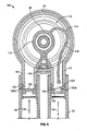
- Figure 5 is a cross-sectional view taken through the pump assembly at the flush water inlet and outlet ports and illustrating a flush mode selector for the pump assembly in accordance with the present teachings, the flush mode selector shown in an open position.
- Figure 6 is a cross-sectional view similar to Figure 5 , illustrating the flush mode selector in a closed position and incorporating alternate valve assemblies.
- Figure 7 is an enlarged cross-sectional view of one of the one-way valves of Figure 5 shown removed from the pump assembly.
- Figure 8 is an enlarged cross-sectional view of one of the one-way valves of Figure 6 shown removed from the pump assembly.
- a pump assembly in accordance with the present teachings is illustrated and generally identified at reference character 10.
- the pump assembly 10 is shown operatively associated with a toilet 12. It will be understood that the particular toilet 12 shown in the drawings is exemplary. In this regard, the pump assembly 10 of the present teachings may be used with other toilets 12 within the scope of the present teachings. Insofar as the present teachings are concerned, the toilet 12 will be understood to be of conventional construction and operation.
- the toilet 12 may generally include a bowl 14 and a base 16.
- the bowl 14 may be constructed of china.
- the base 16 may be constructed of plastic.
- the bowl and base 14 and 16 may be suitable secured to one other.
- the bowl and base 14 and 16 may be constructed of any other suitable materials known in the art.
- the bowl and base 14 and 16 may be unitarily formed of a common material.
- a seat and cover 18 and 20 may be conventionally mounted to the bowl 14.
- the bowl 14 conventionally includes a nozzle for delivering a source of flush water.
- the base 16 may define a hopper 21.
- the hopper 21 may receive waste from the bowl 14 prior to transfer to a holding tank or sewer.
- the pump assembly 10 may be a positive displacement pump and may include a pump body 22.
- the pump body 22 may be connected at an upper end to a pump cap 24 and at a lower end to a pump base 26.
- the base 26 may define a plurality of holes for receiving mounting fasteners.
- the base 26 may further define an input port 30 and an outlet port 32.
- the pump cap 24 may define an opening 34 for slidably receiving a pump rod 36.
- the pump rod 36 may be coupled to a pump handle 38.
- the pump cap 24 may further define a first conduit or flush water inlet port 40 and a second conduit or flush water outlet port 42.
- the pump assembly 10 may be selectively operated in a plurality of modes.
- the pump assembly 10 may be operated in a first mode in which a source of flush water is delivered to the bowl 14 of the toilet 12 and in which waste is pumped from the hopper 21 to a holding tank or sewer.
- the pump assembly 10 may be further operated in a second mode in which waste is pumped from a hopper 21 of the toilet 12 to the holding tank or sewer but flush water is not delivered to the bowl 14.
- the pump assembly 10 may include a mode selector lever 44 or other manual or electronic device for toggling between the first and second modes in a manner discussed below.
- the pump assembly 10 may be coupled to the remainder of the waste transfer system in a flexible manner.
- a first flexible hose 50 may interconnect the flush water source and the inlet port 40.
- a second flexible hose 52 may connect the outlet port 42 and the nozzle of the toilet 12.
- a third flexible hose 54 may connect the outlet port 32 and the holding tank or sewer.
- a fourth flexible hose 56 may connect the inlet port 30 and the hopper 21.
- the present teachings allow for a wide variety of mounting choices for a pump assembly of a flush toilet As such, a single toilet and single pump assembly may be utilized in a greater number of applications where space for mounting is limited or otherwise confined. Additionally, the present teachings provide for a non-directional design. In this regard, the present teachings may be configured as a right or left handed unit. Moreover, the present teachings use less material than conventional molded plastic waste arms, thereby reducing manufacturing costs and additional parts.
- the mode selector is illustrated and generally identified at reference character 110.
- the mode selector 110 is operative in a manner to be further discussed below to control the pump assembly 10 to operate in the first mode or the second mode in response to movement of the mode selector lever 44 or other device.
- the flush water inlet port 40 and the flush water outlet port 42 may be associated with one-way valve assemblies 100.
- the one-way valve assemblies 100 may be of any suitable type operative to seal against back flow of fluid from the first side 102 and open to positive pressure on a second side 104.
- the particular valve assemblies 100 shown in the drawings offer certain advantages, however, and will be described further below. Briefly, a first type of one-way valve assembly 100A is shown associated with the pump assembly 10 in Figure 5 and in the cross-sectional view of Figure 7 . A second type of one-way valve assembly 100B is shown associated with the pump assembly 10 in Figure 6 and in the cross-sectional view of Figure 8 .
- the mode selector 110 may include a first member or first portion 112 for closing the fluid path that extends through the inlet and outlet ports 40 and 42.
- the mode selector 110 may further include a second portion or second member 114 for maintaining one of the one-way valves 100 in an open condition so as to avoid the creation of a vacuum within the system.
- the first portion 112 may be moveable between a first or open position and a second or closed position.
- the open position is shown in Figure 5 , for example.
- the closed position is shown in Figure 6 , for example.
- the first portion 112 may be rotatable about an axis between the first and second positions. The axis may be defined by the pump rod 36.
- the first portion 112 may carry or integrally define a seal portion 116.
- the seal portion 116 may be sized and positioned to seal one of the inlet and outlet ports 40 and 42 when the first portion 112 is rotated to the closed position. As shown in the drawings, the seal portion 116 may seal the inlet port 40. Alternatively, the seal portion 116 may seal the outlet port 42.
- the second portion 114 may include a flexible member 118.
- the flexible member 118 may be in the form of a line, tether or similar structure.
- the flexible member 118 may be attached to or integrally formed with the first portion 112.
- the flexible member 118 may have a length sufficient to extend through one of the valves 100 when the first portion 112 is rotated to the closed position. As illustrated, the flexible member 118 may at least partially extend through the valve 100 associated with the outlet port 42 when the first portion 112 seals the inlet port 40.
- the flush mode selector 110 is shown in Figure 6 in the closed mode.
- the first portion 112 is rotated to its closed position and fluid is prevented from flowing along the fluid path extending between the inlet port 40 and the outlet port 42.
- the end of the flexible portion 118 extends at least partially through the valve 100 associated with the outlet port 42. In this manner, the flush water inlet port 40 of the pump assembly 10 is held shut and the outlet port 42 is held open, thus not allowing material to enter or exit the system, but at the same time not creating a vacuum within the system.
- valve assemblies 100 constructed according to the teachings of the present disclosure will be further described.
- the valve assemblies 100 are particularly adapted for use in the pump assembly 10.
- the teachings of the present disclosure are not limited to the exemplary applications shown in the drawings.
- the valve assemblies 100 have applicability to other fluid transfer arrangements.
- the term fluid will be understood to include liquid, gas and/or slurry type material, such as but not limited to sewage transferred from a toilet to a holding tank or sewer.
- the valve assembly 100A may generally include a mounting portion 120, a seating portion or valve seat 122 and a valve body 124.
- the mounting portion 120 may be generally cylindrical.
- the mounting portion 120 may be of any suitable geometry for mating with a conduit through which flow control is desired.
- the mounting portion 120 may include a first end 126 and a second end 128.
- the first and second ends 126 and 128 may be generally identical to one another.
- the first and second ends 126 and 128 may both be selectively mounted to the inlet port 40 and the outlet port 42 depending upon the direction in which flow control is desired.
- the first and second ends 126 and 128 may be formed to include retention features 130.
- the retention features 130 may be in the form of inwardly extending ribs 130.
- the ribs 130 may engage corresponding grooves 132 defined by the inlet port 40 and the outlet port 42.
- the ends 126 and 128 may be secured to the conduits 116 and 118 through a friction fit or any other manner well known in the art.
- the first end 126 of one of the valve assemblies 100A is attached to the inlet port 40 to allow flow in a first direction 134.
- the second end 128 of another of the valve assemblies 100A is attached to the outlet port 42 to allow flow in a second direction 136.
- the valve seat 122 is interconnected to the mounting portion 120. As shown in the cross-section view of Figure 7 , the valve seat 122 may simply define an inwardly extending circumferential flange against which the valve body 124 may seat.
- the valve seat 122 may include an axially extending portion 140 and an inwardly extending radial flange 142. These elements 140 and 142 may extend directly from the mounting portion 120 or be connected to the mounting portion 120 through a flange 144.
- the valve body 124 may be interconnected to at least one of the mounting portion 120 and the valve seat 122 for movement relative to the valve seat between a seated position and a closed position.
- the valve body 124 may include a first side 148 and a second side 150.
- the valve body 124 is operative to seal against back flow from the first side 148 and open to positive pressures on the second side 150.
- the valve assembly 100 may be unitarily constructed. In certain applications, the valve assembly 100 may be constructed of rubber. Other suitable materials may be employed within the scope of the present teachings.
- valve assembly 100B is shown to share various features in common with the valve assembly 100A. As such, like reference characters are used to identify similar elements throughout the drawings.
- the valve assembly may be a duck-bill type valve assembly 200. As such, the valve body 124 of the valve assembly 200 may be directly coupled to the mounting portion 120 without a seat portion 122. Other features of the valve assembly 200 may be identical to corresponding features described above with respect to valve assembly 100.
Landscapes
- Engineering & Computer Science (AREA)
- Mechanical Engineering (AREA)
- General Engineering & Computer Science (AREA)
- Aviation & Aerospace Engineering (AREA)
- Health & Medical Sciences (AREA)
- Life Sciences & Earth Sciences (AREA)
- Hydrology & Water Resources (AREA)
- Public Health (AREA)
- Water Supply & Treatment (AREA)
- Sanitary Device For Flush Toilet (AREA)
- Multiple-Way Valves (AREA)
Applications Claiming Priority (3)
| Application Number | Priority Date | Filing Date | Title |
|---|---|---|---|
| US89328807P | 2007-03-06 | 2007-03-06 | |
| US89325607P | 2007-03-06 | 2007-03-06 | |
| US89325907P | 2007-03-06 | 2007-03-06 |
Publications (2)
| Publication Number | Publication Date |
|---|---|
| EP1972728A2 true EP1972728A2 (de) | 2008-09-24 |
| EP1972728A3 EP1972728A3 (de) | 2012-10-03 |
Family
ID=39651604
Family Applications (1)
| Application Number | Title | Priority Date | Filing Date |
|---|---|---|---|
| EP20080004063 Withdrawn EP1972728A3 (de) | 2007-03-06 | 2008-03-05 | Spültoilette |
Country Status (2)
| Country | Link |
|---|---|
| US (3) | US7996929B2 (de) |
| EP (1) | EP1972728A3 (de) |
Cited By (4)
| Publication number | Priority date | Publication date | Assignee | Title |
|---|---|---|---|---|
| EP2048361A1 (de) * | 2007-10-09 | 2009-04-15 | Thetford Corporation | Doppelmembranpumpenanordnung für ein Reinigungssystem |
| EP2357289A1 (de) * | 2010-02-16 | 2011-08-17 | Almos Technologies Pty Ltd | Pumpenanordnung für eine Bordtoilette und Verbindungssystem für Toilettenpumpen |
| WO2011101309A1 (en) * | 2010-02-16 | 2011-08-25 | Almos Technologies Pty. Ltd. | Pump assembly for a marine toilet and toilet pump connection system |
| WO2013144141A1 (de) * | 2012-03-27 | 2013-10-03 | Aqua Vital Int. Ltd. & Co. KG | Absaugvorrichtung |
Families Citing this family (9)
| Publication number | Priority date | Publication date | Assignee | Title |
|---|---|---|---|---|
| US7603726B2 (en) * | 2005-12-20 | 2009-10-20 | S.C. Johnson & Son, Inc. | Toilet bowl cleaning and/or deodorizing device |
| EP1972728A3 (de) * | 2007-03-06 | 2012-10-03 | Thetford Corporation | Spültoilette |
| EP2378013A1 (de) | 2010-04-13 | 2011-10-19 | Almos Technologies Pty Ltd | Pumpenanordnung für Schiffstoilette |
| US9556602B2 (en) * | 2013-04-12 | 2017-01-31 | Robert Claunch | Self-contained oil flush toilet unit and sewage treatment system for separating and pre-treating waste |
| US9404247B2 (en) | 2014-02-12 | 2016-08-02 | Raritan Engineering Company, Inc. | Manual toilet flushing apparatus with an odor reducing fresh water inlet valve assembly |
| US9782317B2 (en) | 2014-11-28 | 2017-10-10 | Mary Madeline Mount | Head support device |
| CN106013362B (zh) * | 2015-03-24 | 2018-07-27 | Toto株式会社 | 冲水大便器 |
| CN111492116B (zh) * | 2017-08-07 | 2021-11-02 | 福马有限公司 | 流体控制系统和方法 |
| US11319700B2 (en) * | 2019-03-02 | 2022-05-03 | Ryan M. Fritzsche | Lubrication system for marine or RV toilet |
Family Cites Families (52)
| Publication number | Priority date | Publication date | Assignee | Title |
|---|---|---|---|---|
| US615751A (en) * | 1898-12-13 | Ernest p | ||
| US397782A (en) * | 1889-02-12 | Plunger water-closet | ||
| US205036A (en) * | 1878-06-18 | Improvement in water-closets | ||
| US637399A (en) * | 1898-10-10 | 1899-11-21 | Samuel R Miles | Pump water-closet for ships. |
| US762059A (en) * | 1902-06-04 | 1904-06-07 | J L Mott Iron Works | Pump water-closet. |
| US866368A (en) * | 1906-02-23 | 1907-09-17 | Monroe N Callender | Flushing apparatus. |
| US996588A (en) * | 1909-09-02 | 1911-06-27 | Nat Carbonated Liquid Co | Combined union and check valve. |
| US966588A (en) * | 1910-01-24 | 1910-08-09 | Charles Algernon Parsons | Heating of turbine parts. |
| US1065129A (en) * | 1913-01-11 | 1913-06-17 | Embalmer S Supply Company | Embalming-pump. |
| US1278665A (en) * | 1918-04-12 | 1918-09-10 | Peter C Hunter | Marine toilet. |
| US1329932A (en) * | 1919-07-26 | 1920-02-03 | Henry H Sell | Marine water-closet |
| US1403688A (en) * | 1921-07-09 | 1922-01-17 | Peter C Hunter | Marine toilet |
| BE335155A (de) * | 1925-02-13 | |||
| US1589353A (en) * | 1925-03-30 | 1926-06-22 | Charles A Bock | Floor push-button device for plumbing |
| US1650370A (en) * | 1927-06-08 | 1927-11-22 | David J Mahoney | Marine toilet |
| US1866298A (en) * | 1928-08-03 | 1932-07-05 | Sherwell Controls Inc | Dispensing system for gasoline and the like |
| US1798805A (en) * | 1929-07-03 | 1931-03-31 | Aqua Systems Inc | Liquid dispenser |
| US1888842A (en) * | 1931-05-06 | 1932-11-22 | Sands & Son Company Ab | Marine toilet |
| US2501510A (en) * | 1946-03-27 | 1950-03-21 | Jr Angus Roy Gross | Marine toilet |
| US2598002A (en) * | 1946-08-20 | 1952-05-27 | Jesse D Langdon | Check valve construction |
| US2642259A (en) * | 1947-10-25 | 1953-06-16 | Manitowoc Shipbuilding Company | Valve |
| US3122156A (en) * | 1959-10-21 | 1964-02-25 | Ronald C Kersh | Flexible check valve |
| US3238890A (en) * | 1960-05-19 | 1966-03-08 | Hypro Inc | Piston type pump |
| US3035274A (en) * | 1960-06-28 | 1962-05-22 | Edwin C Baughman | Marine sewage pump and disposal system |
| US3183525A (en) * | 1961-10-04 | 1965-05-18 | Mission West Mfg Company | Method and means for operating a toilet in a fallout shelter |
| US3228036A (en) * | 1963-01-02 | 1966-01-11 | Holley Carburetor Co | Waste treatment system |
| US3422844A (en) * | 1965-03-05 | 1969-01-21 | Grimar Inc | Flexible check valve |
| US3514231A (en) * | 1967-12-01 | 1970-05-26 | Perry Belden | Reciprocating pump for marine toilets |
| BE754192A (fr) * | 1969-07-31 | 1970-12-31 | Hoff Stevens | Soupape de retenue |
| US3594828A (en) * | 1970-02-04 | 1971-07-27 | Wayne Musgrove | Flush valve operating mechanism |
| US3663970A (en) * | 1970-03-30 | 1972-05-23 | Mansfield Sanitary Inc | Apparatus for pneumatic transportation of sanitary waste from a toilet to a holding tank |
| US3675774A (en) * | 1970-09-22 | 1972-07-11 | Monogram Ind Inc | Marine recirculating and holding tank |
| US3822720A (en) * | 1971-03-04 | 1974-07-09 | Noyce R | Flow control assembly |
| US3842445A (en) * | 1972-10-05 | 1974-10-22 | S Jones | Fresh water flush portable toilet |
| US3801017A (en) * | 1973-02-12 | 1974-04-02 | L & A Prod Inc | Manifold for high pressure washer in mechanical mode selection |
| US4319366A (en) * | 1980-02-07 | 1982-03-16 | Baker Jr Roupen | Waste storage apparatus |
| US4426062A (en) * | 1982-02-10 | 1984-01-17 | Black & Decker Inc. | Fluid flow control valves |
| US4477236A (en) * | 1982-04-29 | 1984-10-16 | Elliott Robert E | Liquid end structure for reciprocating pump |
| US4465102A (en) * | 1982-05-17 | 1984-08-14 | The Warren Rupp Company | Check valve |
| US4696602A (en) * | 1986-03-27 | 1987-09-29 | Ltv Energy Products Company | Apparatus and system for flooding submerged structures |
| US5158210A (en) * | 1990-06-13 | 1992-10-27 | Du Benjamin R | Condiment dispensing device |
| US5154589A (en) * | 1990-11-09 | 1992-10-13 | National Instrument Company | Metering pump |
| US5282724A (en) * | 1992-05-12 | 1994-02-01 | Warren Rump, Inc. | Modular check valve system |
| DE4314794A1 (de) * | 1993-05-05 | 1994-12-15 | Hoechst Ag | Schüttgutbehälter mit Bodenauslaufventil |
| JPH07248004A (ja) * | 1994-03-10 | 1995-09-26 | Shin Caterpillar Mitsubishi Ltd | 作業機用油圧回路 |
| US5924452A (en) * | 1997-09-08 | 1999-07-20 | Baxter International Inc. | Valve assembly |
| US6192931B1 (en) * | 1998-07-08 | 2001-02-27 | Research Products Corporation | Damper blade control |
| MXPA01012792A (es) * | 1999-06-15 | 2003-06-24 | Ip One Pty Ltd | Una valvula de retencion. |
| USD468015S1 (en) * | 2001-01-22 | 2002-12-31 | Astra Tech Ab | Combined connector with valve and non-return valve for medical equipment |
| JP3760785B2 (ja) * | 2001-03-21 | 2006-03-29 | 株式会社ジェイ・エム・エス | 弁付回転式コネクタ |
| US6422832B1 (en) * | 2001-03-27 | 2002-07-23 | Lo-Pin Wang | Air pump capable of inflating and deflating an inflatable object interchangeably |
| EP1972728A3 (de) * | 2007-03-06 | 2012-10-03 | Thetford Corporation | Spültoilette |
-
2008
- 2008-03-05 EP EP20080004063 patent/EP1972728A3/de not_active Withdrawn
- 2008-03-06 US US12/043,565 patent/US7996929B2/en not_active Expired - Fee Related
- 2008-03-06 US US12/043,531 patent/US8167587B2/en not_active Expired - Fee Related
- 2008-03-06 US US12/043,608 patent/US20080216225A1/en not_active Abandoned
Cited By (7)
| Publication number | Priority date | Publication date | Assignee | Title |
|---|---|---|---|---|
| EP2048361A1 (de) * | 2007-10-09 | 2009-04-15 | Thetford Corporation | Doppelmembranpumpenanordnung für ein Reinigungssystem |
| US8529223B2 (en) | 2007-10-09 | 2013-09-10 | Thetford Corporation | Dual diaphragm pump assembly for a sanitation system |
| EP2357289A1 (de) * | 2010-02-16 | 2011-08-17 | Almos Technologies Pty Ltd | Pumpenanordnung für eine Bordtoilette und Verbindungssystem für Toilettenpumpen |
| WO2011101309A1 (en) * | 2010-02-16 | 2011-08-25 | Almos Technologies Pty. Ltd. | Pump assembly for a marine toilet and toilet pump connection system |
| US9115486B2 (en) | 2010-02-16 | 2015-08-25 | Almos Technologies Pty. Ltd. | Pump assembly for a marine toilet and toilet pump connection system |
| AU2011217366B2 (en) * | 2010-02-16 | 2015-10-15 | Almos Technologies Pty. Ltd. | Pump assembly for a marine toilet and toilet pump connection system |
| WO2013144141A1 (de) * | 2012-03-27 | 2013-10-03 | Aqua Vital Int. Ltd. & Co. KG | Absaugvorrichtung |
Also Published As
| Publication number | Publication date |
|---|---|
| EP1972728A3 (de) | 2012-10-03 |
| US20080216905A1 (en) | 2008-09-11 |
| US8167587B2 (en) | 2012-05-01 |
| US7996929B2 (en) | 2011-08-16 |
| US20080216224A1 (en) | 2008-09-11 |
| US20080216225A1 (en) | 2008-09-11 |
Similar Documents
| Publication | Publication Date | Title |
|---|---|---|
| US8167587B2 (en) | Pump assembly with reversible one-way valves | |
| US8176580B2 (en) | Diverter spout | |
| US20050126645A1 (en) | Frost free valve assembly | |
| TW200404968A (en) | Stop valve | |
| WO2001008531A1 (en) | Soap dispensing mechanism | |
| KR20040071690A (ko) | 매니폴드 밸브 | |
| JP5388609B2 (ja) | 混合弁ユニット及び貯湯式給湯機 | |
| CN101605943A (zh) | 抽式淋浴排水系统 | |
| US12049174B2 (en) | Subassembly for a holding tank with integrated leak free interface to the holding tank | |
| CA2289388C (en) | Faucet side spray diverter | |
| US3172426A (en) | Proportioning valve | |
| WO2009031994A1 (en) | Faucet type valve with backflow control in handle structure | |
| US7409964B2 (en) | Faucet type valve with backflow control in handle structure | |
| EP1845293A2 (de) | Rückschlagventil | |
| ZA200506519B (en) | Improved mains pressure flusher valve | |
| CA2197996A1 (en) | A sanitary toilet with integral water supply and manual flush assembly | |
| KR200192319Y1 (ko) | 체크밸브 | |
| US20070295404A1 (en) | Siphon and backflow resistant valve | |
| JP5582496B2 (ja) | ボールタップ装置 | |
| US221506A (en) | Improvement in cocks or valves | |
| JPH0433512Y2 (de) | ||
| KR200178525Y1 (ko) | 흡입연결부의 방향조정기능을 갖는 다기능 체크밸브 | |
| KR200322082Y1 (ko) | 수도와 저장수조의 용수 자동 개.폐장치 | |
| JP2021110453A (ja) | 逆止弁ユニット及び水栓装置 | |
| JPS62244741A (ja) | 自動車用ウオツシヤ−液供給装置 |
Legal Events
| Date | Code | Title | Description |
|---|---|---|---|
| PUAI | Public reference made under article 153(3) epc to a published international application that has entered the european phase |
Free format text: ORIGINAL CODE: 0009012 |
|
| AK | Designated contracting states |
Kind code of ref document: A2 Designated state(s): AT BE BG CH CY CZ DE DK EE ES FI FR GB GR HR HU IE IS IT LI LT LU LV MC MT NL NO PL PT RO SE SI SK TR |
|
| AX | Request for extension of the european patent |
Extension state: AL BA MK RS |
|
| RIC1 | Information provided on ipc code assigned before grant |
Ipc: F04B 49/22 20060101ALI20120619BHEP Ipc: E03D 5/01 20060101AFI20120619BHEP Ipc: F04B 53/10 20060101ALI20120619BHEP Ipc: F04B 17/06 20060101ALI20120619BHEP Ipc: F04B 49/10 20060101ALI20120619BHEP Ipc: F04B 9/14 20060101ALI20120619BHEP |
|
| PUAL | Search report despatched |
Free format text: ORIGINAL CODE: 0009013 |
|
| AK | Designated contracting states |
Kind code of ref document: A3 Designated state(s): AT BE BG CH CY CZ DE DK EE ES FI FR GB GR HR HU IE IS IT LI LT LU LV MC MT NL NO PL PT RO SE SI SK TR |
|
| AX | Request for extension of the european patent |
Extension state: AL BA MK RS |
|
| RIC1 | Information provided on ipc code assigned before grant |
Ipc: F04B 53/10 20060101ALI20120827BHEP Ipc: E03D 5/01 20060101AFI20120827BHEP Ipc: F04B 49/10 20060101ALI20120827BHEP Ipc: F04B 17/06 20060101ALI20120827BHEP Ipc: F04B 9/14 20060101ALI20120827BHEP Ipc: F04B 49/22 20060101ALI20120827BHEP |
|
| STAA | Information on the status of an ep patent application or granted ep patent |
Free format text: STATUS: THE APPLICATION IS DEEMED TO BE WITHDRAWN |
|
| 18D | Application deemed to be withdrawn |
Effective date: 20121002 |