EP1972805A2 - Dispositif de mouvement linéaire fini - Google Patents
Dispositif de mouvement linéaire fini Download PDFInfo
- Publication number
- EP1972805A2 EP1972805A2 EP07011663A EP07011663A EP1972805A2 EP 1972805 A2 EP1972805 A2 EP 1972805A2 EP 07011663 A EP07011663 A EP 07011663A EP 07011663 A EP07011663 A EP 07011663A EP 1972805 A2 EP1972805 A2 EP 1972805A2
- Authority
- EP
- European Patent Office
- Prior art keywords
- rail
- holding device
- rotating body
- rolling
- cord
- Prior art date
- Legal status (The legal status is an assumption and is not a legal conclusion. Google has not performed a legal analysis and makes no representation as to the accuracy of the status listed.)
- Withdrawn
Links
- 238000005096 rolling process Methods 0.000 claims abstract description 109
- 230000002093 peripheral effect Effects 0.000 claims description 5
- 230000002146 bilateral effect Effects 0.000 claims description 2
- 238000006073 displacement reaction Methods 0.000 description 7
- 230000007423 decrease Effects 0.000 description 6
- 238000004873 anchoring Methods 0.000 description 4
- 239000011347 resin Substances 0.000 description 2
- 229920005989 resin Polymers 0.000 description 2
- 230000015572 biosynthetic process Effects 0.000 description 1
- 230000000694 effects Effects 0.000 description 1
Images
Classifications
-
- F—MECHANICAL ENGINEERING; LIGHTING; HEATING; WEAPONS; BLASTING
- F16—ENGINEERING ELEMENTS AND UNITS; GENERAL MEASURES FOR PRODUCING AND MAINTAINING EFFECTIVE FUNCTIONING OF MACHINES OR INSTALLATIONS; THERMAL INSULATION IN GENERAL
- F16C—SHAFTS; FLEXIBLE SHAFTS; ELEMENTS OR CRANKSHAFT MECHANISMS; ROTARY BODIES OTHER THAN GEARING ELEMENTS; BEARINGS
- F16C29/00—Bearings for parts moving only linearly
- F16C29/04—Ball or roller bearings
- F16C29/041—Ball or roller bearings having rollers crossed within a row
-
- F—MECHANICAL ENGINEERING; LIGHTING; HEATING; WEAPONS; BLASTING
- F16—ENGINEERING ELEMENTS AND UNITS; GENERAL MEASURES FOR PRODUCING AND MAINTAINING EFFECTIVE FUNCTIONING OF MACHINES OR INSTALLATIONS; THERMAL INSULATION IN GENERAL
- F16C—SHAFTS; FLEXIBLE SHAFTS; ELEMENTS OR CRANKSHAFT MECHANISMS; ROTARY BODIES OTHER THAN GEARING ELEMENTS; BEARINGS
- F16C33/00—Parts of bearings; Special methods for making bearings or parts thereof
- F16C33/30—Parts of ball or roller bearings
- F16C33/306—Means to synchronise movements
-
- F—MECHANICAL ENGINEERING; LIGHTING; HEATING; WEAPONS; BLASTING
- F16—ENGINEERING ELEMENTS AND UNITS; GENERAL MEASURES FOR PRODUCING AND MAINTAINING EFFECTIVE FUNCTIONING OF MACHINES OR INSTALLATIONS; THERMAL INSULATION IN GENERAL
- F16C—SHAFTS; FLEXIBLE SHAFTS; ELEMENTS OR CRANKSHAFT MECHANISMS; ROTARY BODIES OTHER THAN GEARING ELEMENTS; BEARINGS
- F16C33/00—Parts of bearings; Special methods for making bearings or parts thereof
- F16C33/30—Parts of ball or roller bearings
- F16C33/46—Cages for rollers or needles
- F16C33/54—Cages for rollers or needles made from wire, strips, or sheet metal
Definitions
- the present invention relates to a finite linear motion device.
- a finite linear motion device proposed in the conventional art and comprising a pair of rails provided with rolling grooves, a plurality of rolling bodies disposed in a rolling path formed by the rolling grooves between the rails, and a holding device for holding the rolling bodies at predetermined intervals
- the holding device is formed separately from the rails and does not move in conjunction with the rails. Therefore, the movement of the rails and the movement of the holding device are different.
- the holding device and stopper screws on both end parts of the rolling path make mutual contact or another such incident occurs, and problems arise in that a highly precise linear motion cannot be made and a predetermined stroke cannot be achieved.
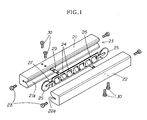
- a device proposed as disclosed in Published Unexamined Utility Model Application No. 4-88523 is a finite linear motion device comprising a first rail 21 in which is formed a first rolling groove 21a having a transverse V-shaped cross section, a second rail 22 disposed facing the first rail 21 and provided with a second rolling groove 22a having a transverse V-shaped cross section, a plurality of rolling bodies 24 that are disposed in a rolling path 23 formed by the rolling grooves 21a, 22a of the facing first rail 21 and second rail 22 and that roll over the rolling path 23, and a holding device 26 for rollably holding the rolling bodies 24 at predetermined intervals.
- pulleys 25 are provided to end parts of the holding device 26, and a wire 27 connected to an anchoring plate 29 provided to the rails 21, 22 is pulled toward the pulleys 25.
- the holding device 26 is suspended and made to move in conjunction with the movement of the rails 21, 22, and the holding device 26 is prevented from deviating (referred to below as "the conventional example of the art"; shown in FIG. 1 ).
- the reference symbol 28 indicates a stopper screw for stopping the fall of the holding device 26, and the reference symbol 30 indicates a screw for anchoring the anchoring plate 29 to the rails 21, 22.
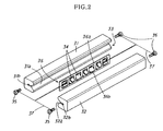
- the invention according to Patent Document 2 is a finite linear motion device comprising a first rail 31 in which a first rolling groove 31a is formed; a second rail 32 disposed facing the first rail 31 and provided with a second rolling groove 32a; a plurality of rolling bodies 34 that is disposed in a rolling path 33 formed by the rolling grooves 31a, 32a of the facing first rail 31 and second rail 32, and that rolls over the rolling path 33; and a holding device 36 for rollably holding the rolling bodies 34 at predetermined intervals.
- an end of a cord 37 of a predetermined length is connected to a distal end part of the first rail 31; the other end of the cord 37 is extended to and slidably wrapped around the rolling body 34 held at a distal end side of the holding device 36 and is connected to a distal end part of the second rail 32; an end of another cord 37 of a predetermined length is connected to a proximal end part of the first rail 31; and the other end of the cord 37 is extended to and slidably wrapped around the rolling body 34 held on a proximal end side of the holding device 36, and is connected to a proximal end part of the second rail 32.
- reference symbols 31b and 32b indicate screw holes into which are screwed stopper screws 35, and ends of the cord 37 are wrapped around the stopper screws;
- reference symbol 36a indicates a plate body, and the reference symbol 36b indicates windows in which the rolling bodies 34 are held.
- the present invention was devised in view of the foregoing circumstances, and it is an object thereof to provide a finite linear motion device that has an uncomplicated configuration and that has exceptional utility.
- a holding device can be prevented from deviating, a compact design can be employed without hindering smooth travel, a cord is not readily worn, and durability is correspondingly improved.
- the present invention provides a finite linear motion device comprising a first rail 1 provided with a first rolling groove 1a, a second rail 2 disposed facing the first rail 1 and provided with a second rolling groove 2a, a plurality of rolling bodies 4 that is disposed in a rolling path 3 formed by the rolling grooves 1a, 2a of the facing first rail 1 and second rail 2 and that rolls over the rolling path 3, and a holding device 5 for rollably holding the rolling bodies 4 at predetermined intervals; wherein one end of a cord 6 of a predetermined length is connected to a distal end part of the first rail 1; the other end of the cord 6 is extended to and slidably wrapped around a first rotating body 7 that is rotatably provided at a position near a center of the holding device 5 in a length direction, and is connected to a distal end part of the second rail 2; an end of another cord 6 of a predetermined length is connected to a proximal end part of the first rail 1; another end of the other cord 6 is extended to and
- a finite linear motion device is provided in which, in the finite linear motion device according to the first aspect, the first rotating body 7 and second rotating body 8 are disposed alongside each other in the length direction of the holding device 5.
- a finite linear motion device is provided in which, in the finite linear motion device according to the second aspect, the first rotating body 7 and second rotating body 8 are provided to a substantially center part of the holding device 5.
- a finite linear motion device in which, in the finite linear device according to any of the first through third aspects, the first rotating body 7 and second rotating body 8 are provided in a substantially bilateral symmetric relationship on either side of a center point of the holding device 5 in the length direction.
- a finite linear motion device in which, in the finite linear device according to any of the first through fourth aspects, the first rolling groove 1a and second rolling groove 2a are formed so as to be v-shaped in cross-section.
- a finite linear motion device in which, in the finite linear device according to the fifth aspect, clearance concavities 1c, 2c for providing clearance relative to a grinding body that grinds the first rolling groove 1a or second rolling groove 2a is provided to bottom parts of the first rolling groove 1a and second rolling grove 2a; and outer peripheral parts of the first rotating body 7 and the second rotating body 8, and cords 6 are disposed in the clearance concavities 1c, 2c.
- the present invention provides a finite linear motion device that has an uncomplicated configuration and has extremely exceptional utility.
- a holding device can be prevented from deviating, a compact design can be employed without hindering smooth travel, a cord is not readily worn, and durability is correspondingly improved.
- a holding device 5 When a first rail 1 is moved relative to a second rail 2, a holding device 5 is forcibly moved by a first rotating body 7 held by the holding device 5 and a cord 6 of a predetermined length that is wrapped around a second rotating body 8.
- the amount that the holding device is moved is restricted to 1/2 the amount that the first rail 1 and second rail 2 move. Therefore, deviation between the first and second rails 1, 2 and the holding device 5 is prevented.
- the cord 6 is wrapped around the first rotating body 7 and second rotating body 8 that rotate independently of the rolling bodies 4 (independent of the movement of the rails 1, 2). Therefore, the problems that arise in Patent Document 2 do not occur (the cord 37 of Patent Document 2 is wrapped around the rolling bodies 34, which rotate in conjunction with the movement of the rails 31, 32). Therefore, friction does not readily arise between the first and second rotating bodies 7, 8 and the cord 6, and wearing of the cord 6 is correspondingly minimized.
- the first rotating body 7 and the second rotating body 8 are provided to positions near a center of the holding device 5.
- At least two or more rolling bodies 4 can be provided to the holding device in each of the area between the first rotating body 7 and the distal end part of the holding device 5 and the area between the second rotating body 8 and the proximal end part of the holding device 5.
- a moment load can thereby be borne by the rolling bodies 4 positioned at both ends of the holding device 5 even when the first rail 1 and second rail 2 are moved in a mutually relative fashion and the rails 1, 2 are both placed in a substantially cantilevered state.
- the rotating body (pulley) is provided to both ends of the holding device rather than to a center of the holding device and the pulley is pulled toward an interior of the rails
- the pulley cannot bear a load as the rolling bodies can. Therefore, the amount of displacement under load is greater than in the present invention (the amount of displacement under load at a position near the end parts of the holding device decreases to the extent that the load can be borne by the rolling bodies).
- the first rotating body 7 and the second rotating body 8 are provided to positions near the center of the holding device 5. Therefore, rolling bodies for bearing a load can be provided to end parts of the holding device, displacement under load is low, the moment load can favorably be borne, deviation is minimized in the holding device, and the first rail and second rail can favorably be moved in mutually relative fashion.
- the present invention is a finite linear motion device in which the holding device can be properly moved without a rack and pinion being provided, smooth travel can be achieved, and a compact design can be employed. Furthermore, the cord is not readily worn and exceptional durability is correspondingly obtained.
- the present example is a finite linear motion device comprising a first rail 1 in which a first rolling groove 1a is formed, a second rail 2 disposed facing the first rail 1 and provided with a second rolling groove 2a, a plurality of rolling bodies 4 that is disposed in a rolling path 3 formed by the rolling grooves 1a, 2a of the facing first rail 1 and second rail 2 and that rolls over the rolling path 3, and a holding device 5 for rollably holding the rolling bodies 4 at predetermined intervals; wherein one end of a cord 6 of a predetermined length is connected to a distal end part of the first rail 1; the other end of the cord 6 is extended to and slidably wrapped around a first rotating body 7 that is rotatably provided at a position near a center of the holding device 5 in a length direction, and is connected to a distal end part of the second rail 2; an end of a cord 6 of a predetermined length is connected to a proximal end part of the first rail 1; the other end of the cord 6 is extended
- the first rail 1 and second rail 2 are metallic bodies that are substantially square-shaped in cross section.
- the rolling grooves 1a, 2a that are transversely V-shaped in cross section extend in a longitudinal direction on facing inner surfaces of the first rail 1 and second rail 2.
- the facing rolling grooves 1a, 2a form the rolling path 3 that is rhombus-shaped in cross section and in which the rolling bodies 4 are disposed.
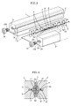
- Clearance concavities 1c, 2c for providing clearance relative to a grinding body (grindstone) when the grinding body is used to grind (finish) wall surfaces of the rolling grooves 1a, 2a (downward-facing surfaces and upward-facing surfaces in FIG. 3 ) are formed on bottom parts of the cross-sectionally transverse V-shaped rolling grooves 1a, 2a.
- a plurality of the rolling bodies 4 is disposed in linear fashion in the rolling path 3 in a state of being held by the holding device 5.
- cylindrical objects are used for the rolling bodies 4.
- the rolling bodies 4 are held by the holding device 5 in a state in which adjacent rolling bodies 4 and axial centers thereof are tilted 90 degrees from one another.
- the holding device 5 is configured so that a plurality of windows 5b for holding the rolling bodies 4 is formed on a plate body 5a.
- the rolling bodies 4 make contact with inner edges of the windows 5b and are held.
- the first rotating body 7 and the second rotating body 8 are provided to the center part of the holding device 5 in linear fashion so as to be on either side of a center point of the holding device 5 in the length direction.
- the first rotating body 7, second rotating body 8, and rolling bodies 4 are provided in a substantially bilaterally symmetrical fashion on either side of the center point of the holding device 5 in the length direction.
- the holding device 5 is configured so that three of the rolling bodies 4 are provided each to the area between the first rotating body 7 and the distal end part of the holding device 5, and to the area between the second rotating body 8 and the proximal end part of the holding device 5.
- the holding device 5 may be configured so that the positions of the first and second rotating bodies 7, 8 and the positions of the rolling bodies 4 on the innermost sides in FIG. 3 are switched so that the rolling bodies 4 are disposed between the rotating bodies 7, 8.
- a configuration may alternatively be employed in which a rolling body is added between the rotating bodies 7, 8 so that the rolling body 4 is disposed between the rotating bodies 7, 8.
- resin pulleys are used for the rotating bodies 7, 8. These pulleys are rotatably provided via an axle 11 inserted into a shaft hole 12 that is provided to a laterally dividable resin holder 9. The holder 9 is anchored to the windows 5d of the holding device 5.
- a groove 13 in which the cord 6 (metallic wire) is disposed is formed on outer peripheral parts of the rotating bodies 7, 8.
- the radius and width of the rotating bodies 7, 8 are set so that the rotating bodies will be accommodated in the clearance concavities 1c, 2c as shown in FIG. 4 so that the cord 6 and the outer peripheral parts in which the groove 13 is formed will not interfere with the rolling bodies 4.
- two cords 6 are attached to the rotating bodies 7, 8, and the cords 6 can be wound and unwound in accordance with the movement of the rolling bodies 4, instead of one cord 6 being wrapped around the rotating bodies.
- Such a configuration will result in the same action and effect as the above-described present example.
- the length of the cords 6 is set so that, e.g., the cord 6 on a front side (movement direction side) of the holding device 5 is tightened when the holding device 5 moves less than 1/2 the amount that the first rail 1 moves, and the rolling bodies 4 are pulled forward by the tightening action, whereby the holding device 5 is forcibly pulled forward.
- the cord 6 on the rear side of the holding device 5 (the side opposite the moving direction) is tightened when the holding device 5 moves more than 1/2 the amount that the first rail 1 moves, and the rolling bodies 4 are pulled rearward by the tightening action, whereby the holding device 5 is forcibly pulled rearward.
- the cords 6 should be suitably set to a length at which partial slackness (excessive length) is avoided and at which the movement of the rolling bodies 4 is not hindered (excessively short) so that the above-described action can be produced.
- Stopper screws 10 for stopping the holding device 5 from falling are provided to end surfaces of the first rail 1 and second rail 2.
- the stopper screws 10 anchor the end parts of the cords 6 to the end parts of the first rail 1 and second rail 2. Specifically, one end of each of the cords 6 is wrapped around the male screw part 10a of the corresponding stopper screws 10, and the male screw parts 10a are screwed into female screw parts 1b, 2b provided to the end surfaces of the first rail 1 and second rail 2. Therefore, a special screw or other implement for anchoring the cords 6 is not necessary, and the configuration is correspondingly made less complex.
- the holding device 5 is forcibly moved by the first rotating body 7 held by the holding device 5 and by the cords 6 of a predetermined length wrapped around the second rotating body 8. Deviation between the first and second rail 1 and second rail 2 and the holding device 5 is prevented because the amount that the holding device moves is restricted to 1/2 the amount that the first rail 1 and second rail 2 move.
- the cords 6 are wrapped around the first rotating body 7 and second rotating body 8, which rotate independently of the rolling bodies 4. Therefore, the problems arising in Patent Document 2 do not occur. Consequently, friction does not readily occur between the first and second rotating bodies 7, 8 and the cords 6, and wearing of the cords 6 is correspondingly reduced.
- the first rotating body 7 and the second rotating body 8 are provided at positions near the center of the holding device 5 in which two or more of the rolling bodies 4 can be provided between the first and second rotating bodies 7, 8 and both ends of the holding device 5.
- a moment load can thereby be borne by the rolling bodies 4 positioned at both sides of the holding device 5 even when the first rail 1 and second rail 2 are moved relative to one another and the rails 1, 2 are both placed in a substantially cantilevered state. There is therefore a decrease in the displacement of the rails 1, 2 under load; and pitching, yawing, and rolling decrease during travel.
- first rolling groove 1a and second rolling groove 2a are formed to be transversely V-shaped in cross-section
- the clearance concavities 1c, 2c for providing clearance relative to the grinding body that grinds the first rolling groove 1a or second rolling groove 2a are provided to the bottom parts of the first and second rolling grooves
- the cords 6 and the outer peripheral parts of the first rotating body 7 and second rotating body 8 are disposed in the clearance concavities 1c, 2c, respectively. Therefore, the first rotating body 7, second rotating body 8, and cords 6 can be readily disposed without any interference with other members by using the clearance concavities 1c, 2c, which are necessary in the formation of the first rolling groove 1a and second rolling groove 2a.
- the present example is a finite linear motion device in which the holding device can be properly moved without a rack and pinion being provided, smooth travel can be achieved; a compact design can be employed. Furthermore, the cord is not readily worn and exceptional durability is correspondingly obtained.
Landscapes
- Engineering & Computer Science (AREA)
- General Engineering & Computer Science (AREA)
- Mechanical Engineering (AREA)
- Bearings For Parts Moving Linearly (AREA)
Applications Claiming Priority (1)
| Application Number | Priority Date | Filing Date | Title |
|---|---|---|---|
| JP2007071254A JP4053580B1 (ja) | 2007-03-19 | 2007-03-19 | 有限直線運動装置 |
Publications (2)
| Publication Number | Publication Date |
|---|---|
| EP1972805A2 true EP1972805A2 (fr) | 2008-09-24 |
| EP1972805A3 EP1972805A3 (fr) | 2009-07-01 |
Family
ID=38330028
Family Applications (1)
| Application Number | Title | Priority Date | Filing Date |
|---|---|---|---|
| EP07011663A Withdrawn EP1972805A3 (fr) | 2007-03-19 | 2007-06-14 | Dispositif de mouvement linéaire fini |
Country Status (2)
| Country | Link |
|---|---|
| EP (1) | EP1972805A3 (fr) |
| JP (1) | JP4053580B1 (fr) |
Cited By (1)
| Publication number | Priority date | Publication date | Assignee | Title |
|---|---|---|---|---|
| CN105156472A (zh) * | 2015-08-17 | 2015-12-16 | 热川精密机械(昆山)有限公司 | 一种直线导轨 |
Families Citing this family (2)
| Publication number | Priority date | Publication date | Assignee | Title |
|---|---|---|---|---|
| JP5208832B2 (ja) * | 2009-03-31 | 2013-06-12 | 日本トムソン株式会社 | 保持器のずれ防止機構を備えた有限直動案内ユニット |
| KR101092978B1 (ko) | 2009-10-12 | 2011-12-12 | (주)원에스티 | 직선운동 안내 유닛 |
Citations (2)
| Publication number | Priority date | Publication date | Assignee | Title |
|---|---|---|---|---|
| JPH03109085U (fr) | 1990-02-16 | 1991-11-08 | ||
| JPH0488523U (fr) | 1990-12-20 | 1992-07-31 |
Family Cites Families (7)
| Publication number | Priority date | Publication date | Assignee | Title |
|---|---|---|---|---|
| CH280851A (fr) * | 1949-11-30 | 1952-02-15 | Paillard Sa | Dispositif de guidage d'un ensemble mobile sur un support fixe. |
| CH288636A (fr) * | 1949-11-30 | 1953-01-31 | Paillard Sa | Dispositif de guidage d'un ensemble mobile sur un support fixe. |
| JP2628377B2 (ja) * | 1989-06-19 | 1997-07-09 | 日本トムソン株式会社 | 保持器の位置ずれ防止装置つき薄肉形有限直動案内ユニット |
| US5116141A (en) * | 1990-11-01 | 1992-05-26 | Anwar Chitayat | Anti-creep for bearing retainers |
| JP2540163Y2 (ja) * | 1990-12-20 | 1997-07-02 | 日本トムソン株式会社 | 薄肉形有限直動案内ユニット |
| US5251984A (en) * | 1991-12-20 | 1993-10-12 | Nippon Thompson Co., Ltd. | Linear motion guide unit having a synchronized retainer |
| JP2001165160A (ja) * | 1999-09-30 | 2001-06-19 | Nikon Corp | 直線案内装置 |
-
2007
- 2007-03-19 JP JP2007071254A patent/JP4053580B1/ja active Active
- 2007-06-14 EP EP07011663A patent/EP1972805A3/fr not_active Withdrawn
Patent Citations (2)
| Publication number | Priority date | Publication date | Assignee | Title |
|---|---|---|---|---|
| JPH03109085U (fr) | 1990-02-16 | 1991-11-08 | ||
| JPH0488523U (fr) | 1990-12-20 | 1992-07-31 |
Cited By (1)
| Publication number | Priority date | Publication date | Assignee | Title |
|---|---|---|---|---|
| CN105156472A (zh) * | 2015-08-17 | 2015-12-16 | 热川精密机械(昆山)有限公司 | 一种直线导轨 |
Also Published As
| Publication number | Publication date |
|---|---|
| JP4053580B1 (ja) | 2008-02-27 |
| JP2008232232A (ja) | 2008-10-02 |
| EP1972805A3 (fr) | 2009-07-01 |
Similar Documents
| Publication | Publication Date | Title |
|---|---|---|
| US8313239B2 (en) | Adjustable preload type linear guide system | |
| CN103492758B (zh) | 直线移动导向机构 | |
| CN112424097B (zh) | 运输系统及运输设备 | |
| KR20110020737A (ko) | 컨베이어 설비용 지지 장치 및 컨베이어 설비의 작동 방법 | |
| EP1972805A2 (fr) | Dispositif de mouvement linéaire fini | |
| US20040159528A1 (en) | Axle cartridge for conveyor roller | |
| CN107630996B (zh) | 丝杠装置 | |
| US20120192668A1 (en) | Deflector for ball screw | |
| KR102448141B1 (ko) | 2축 바퀴 장치 | |
| US20060156845A1 (en) | Self-Retaining Recirculating Ball-Worm and Gear Device | |
| EP3203115B1 (fr) | Actionneur linéaire entraîné par courroie | |
| US10598262B2 (en) | Gearless speed reducer or increaser | |
| US20100129012A1 (en) | Rolling element retainer | |
| EP1403541B1 (fr) | Palier à roulement linéaire avec rouleaux retenus dans une cage flexible | |
| JP2011043192A (ja) | ガイド装置 | |
| EP1536152A2 (fr) | Dispositif à glissière | |
| EP1801458B1 (fr) | Vis à rouleaux | |
| JP2000161459A (ja) | クロスローラねじ装置 | |
| US11767882B2 (en) | Motion guide apparatus | |
| JP2005180602A (ja) | ガイド機構 | |
| JPH1163143A (ja) | アクチュエータ | |
| JP5909848B2 (ja) | 直動案内軸受装置 | |
| WO2006126452A1 (fr) | Vis a billes et dispositif de guidage du mouvement | |
| EP1953399A1 (fr) | Dispositif de guidage de mouvement | |
| TW200517597A (en) | Linear guide device with offset load prevention mechanism |
Legal Events
| Date | Code | Title | Description |
|---|---|---|---|
| PUAI | Public reference made under article 153(3) epc to a published international application that has entered the european phase |
Free format text: ORIGINAL CODE: 0009012 |
|
| AK | Designated contracting states |
Kind code of ref document: A2 Designated state(s): AT BE BG CH CY CZ DE DK EE ES FI FR GB GR HU IE IS IT LI LT LU LV MC MT NL PL PT RO SE SI SK TR |
|
| AX | Request for extension of the european patent |
Extension state: AL BA HR MK RS |
|
| PUAL | Search report despatched |
Free format text: ORIGINAL CODE: 0009013 |
|
| AK | Designated contracting states |
Kind code of ref document: A3 Designated state(s): AT BE BG CH CY CZ DE DK EE ES FI FR GB GR HU IE IS IT LI LT LU LV MC MT NL PL PT RO SE SI SK TR |
|
| AX | Request for extension of the european patent |
Extension state: AL BA HR MK RS |
|
| STAA | Information on the status of an ep patent application or granted ep patent |
Free format text: STATUS: THE APPLICATION HAS BEEN WITHDRAWN |
|
| 18W | Application withdrawn |
Effective date: 20091007 |